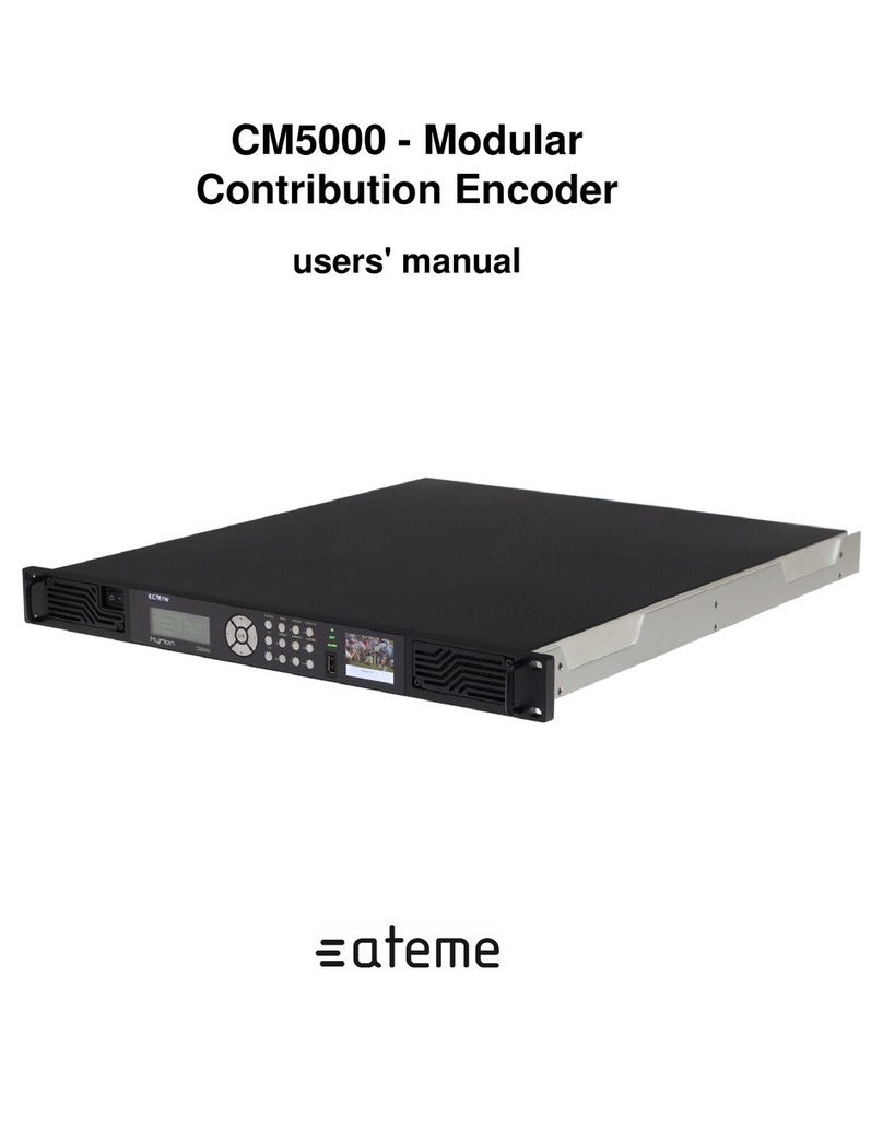
ATEME Kyrion DR5000 User manual

DR5000 - Modular Contribution Decoder
User Manual

DR5000 User Manual UM-DR5000-FW1.2.1.0-REV1.0
2015-02-13
www.ateme.com Page ii
Table of Contents
1. Document Overview ...................................................................................................................... 7
1.1. Document identification ....................................................................................................... 7
1.2. Disclaimer ......................................................................................................................... 8
1.3. Copyrights ......................................................................................................................... 9
1.4. Precautions ....................................................................................................................... 10
2. Product Overview ........................................................................................................................ 11
2.1. Package Content ............................................................................................................... 11
2.2. Front View ....................................................................................................................... 12
2.3. Rear View ........................................................................................................................ 13
2.3.1. DVB-S2 IO Interfaces ............................................................................................. 14
2.3.2. ASI IO Interfaces .................................................................................................... 15
2.3.3. SDI Output Interfaces .............................................................................................. 15
2.3.4. Synchonization IO Interfaces .................................................................................... 16
2.3.5. Ethernet IO Interfaces .............................................................................................. 16
2.3.6. Ethernet Management Interface ................................................................................. 17
2.3.7. Audio Out Interfaces ............................................................................................... 17
2.3.8. Analog Audio Out Interfaces .................................................................................... 17
2.4. Ventilation ....................................................................................................................... 19
3. Installation .................................................................................................................................. 20
3.1. Setting Up Your Device ..................................................................................................... 20
3.2. Quick start ....................................................................................................................... 21
3.2.1. Setting up the Management IP Address ....................................................................... 21
3.2.2. Accessing the Web GUI ........................................................................................... 21
4. User Interfaces ............................................................................................................................ 23
4.1. Three configuration tools .................................................................................................... 23
4.2. Front Panel ...................................................................................................................... 24
4.2.1. Status LED ............................................................................................................ 24
4.2.2. LCD ..................................................................................................................... 24
4.2.3. TFT ...................................................................................................................... 25
4.2.4. Keypad ................................................................................................................. 25
4.2.5. USB ..................................................................................................................... 25
4.2.6. Menus ................................................................................................................... 25
4.3. Web GUI ......................................................................................................................... 34
4.3.1. Gui Overview ......................................................................................................... 34
4.3.2. Decoding Status Panels ............................................................................................ 35
4.3.3. Configuration Panel ................................................................................................. 41
5. Setting up a configuration ............................................................................................................. 62
5.1. Overview ......................................................................................................................... 62
5.2. Input ............................................................................................................................... 63
5.2.1. ASI Input .............................................................................................................. 63
5.2.2. DVB-S/S2 Input ..................................................................................................... 63
5.2.3. IP Input ................................................................................................................. 65
5.2.4. ZIXI Input ............................................................................................................. 70
5.3. Service Selection ............................................................................................................... 72
5.3.1. Service Editor ........................................................................................................ 73
5.3.2. Video Output ......................................................................................................... 74
5.3.3. Audio Output ......................................................................................................... 74
5.4. Biss/CA ........................................................................................................................... 81
5.4.1. BISS parameters ..................................................................................................... 82
5.4.2. CA parameters ....................................................................................................... 83
5.5. Data Output ...................................................................................................................... 84

DR5000 User Manual UM-DR5000-FW1.2.1.0-REV1.0
2015-02-13
www.ateme.com Page iii
5.5.1. Ancillary Data ........................................................................................................ 86
5.5.2. VBI Data ............................................................................................................... 89
5.5.3. Overlay ................................................................................................................. 90
5.6. SDI Output ...................................................................................................................... 91
5.6.1. SDI Connector Mapping .......................................................................................... 91
5.6.2. SDI Settings ........................................................................................................... 92
5.7. Stream Forwarding ............................................................................................................ 95
5.7.1. ASI Output ............................................................................................................ 95
5.7.2. IP Output .............................................................................................................. 96
5.7.3. Remux Output ........................................................................................................ 97
5.8. MPE ............................................................................................................................... 99
6. Specific Operations .................................................................................................................... 100
6.1. Installing License ............................................................................................................. 100
6.2. Recovery ........................................................................................................................ 101
A. MIB User Guide ....................................................................................................................... 102
A.1. SNMP Overview ............................................................................................................. 102
A.2. MIB Overview ............................................................................................................... 104
A.2.1. Main nodes ......................................................................................................... 105
A.3. MIB Use Cases .............................................................................................................. 108
A.3.1. Identification process ............................................................................................ 108
A.3.2. Configuration lock ................................................................................................ 108
A.3.3. Rebooting the system ............................................................................................ 108
A.3.4. Setting time ......................................................................................................... 109
A.3.5. Configuring communities and traps .......................................................................... 109
A.3.6. Configuring network interfaces ............................................................................... 110
A.3.7. Configuring routes ................................................................................................ 111
A.3.8. Saving and loading a preset .................................................................................... 112
A.3.9. ASI Input ............................................................................................................ 113
A.3.10. IP Input ............................................................................................................. 113
A.3.11. IP Input with FEC .............................................................................................. 114
A.3.12. IP Input with Failover .......................................................................................... 115
A.3.13. DVB-S/S2 Input ................................................................................................. 116
A.3.14. Automatic audio composition ................................................................................ 118
A.3.15. Manual composition ............................................................................................ 118
A.3.16. Configuring Biss-E .............................................................................................. 119
A.3.17. Clock synchronization .......................................................................................... 120
A.3.18. IP Forwarding .................................................................................................... 121
A.3.19. Forward remux ................................................................................................... 121
A.3.20. Checking composition results ................................................................................ 122
A.3.21. TS Descriptor ..................................................................................................... 123
B. Input Statistics .......................................................................................................................... 126
B.1. Input Statistics Overview .................................................................................................. 126
B.2. Input Statistics File Format ............................................................................................... 127
C. Appendix ................................................................................................................................. 131
C.1. Product's specification ...................................................................................................... 131
C.2. Warranty ....................................................................................................................... 138
C.3. Normative Reference ....................................................................................................... 139
C.4. Glossary ........................................................................................................................ 140
C.5. Support and Ressources .................................................................................................... 143

DR5000 User Manual UM-DR5000-FW1.2.1.0-REV1.0
2015-02-13
www.ateme.com Page iv
List of Figures
2.1. Front View Interface .................................................................................................................. 12
2.2. Rear View Interface example 1 .................................................................................................... 13
2.3. Rear View Interface example 2 .................................................................................................... 13
2.4. DVB-S/S2 Input/Output Interfaces ................................................................................................ 14
2.5. ASI Input/Output Interfaces ........................................................................................................ 15
2.6. SDI Output Interfaces ................................................................................................................ 15
2.7. Synchronization Interfaces .......................................................................................................... 16
2.8. Stream Ethernet Interfaces .......................................................................................................... 16
2.9. Management Ethernet Interface .................................................................................................... 17
2.10. Audio Output Interfaces ............................................................................................................ 17
2.11. Analog Output Interfaces .......................................................................................................... 18
2.12. Cool air intakes on the front panel .............................................................................................. 19
2.13. Warm air outputs on the rear panel ............................................................................................. 19
3.1. Accessing the Web GUI ............................................................................................................. 22
4.1. Front Panel sub-elements' identification ......................................................................................... 24
4.2. Gui Overview ........................................................................................................................... 34
4.3. Decoding Status panels .............................................................................................................. 35
4.4. Active service overview ............................................................................................................. 36
4.5. Probed programs ....................................................................................................................... 38
4.6. Sat Input status example ............................................................................................................. 39
4.7. IP Input status example .............................................................................................................. 40
4.8. Status Panel .............................................................................................................................. 42
4.9. Service Panel View ................................................................................................................... 44
4.10. Network Panel ........................................................................................................................ 47
4.11. Time Panel ............................................................................................................................. 49
4.12. Alarms and Traps Panel View .................................................................................................... 50
4.13. System Descrambling Parameters view ........................................................................................ 55
4.14. Licenses view ......................................................................................................................... 56
4.15. Firmware and Troubleshooting view ........................................................................................... 57
5.1. Input Type Parameter ................................................................................................................. 63
5.2. DVB-S2 Settings View .............................................................................................................. 64
5.3. IP Settings View ....................................................................................................................... 66
5.4. ZIXI Settings View ................................................................................................................... 71
5.5. Service Selection View .............................................................................................................. 72
5.6. Descrambling Parameters view .................................................................................................... 81
5.7. Data Output View ..................................................................................................................... 85
5.8. Output parameters view .............................................................................................................. 91
5.9. Stream Forwarding View ............................................................................................................ 95
5.10. MPE Settings View .................................................................................................................. 99

DR5000 User Manual UM-DR5000-FW1.2.1.0-REV1.0
2015-02-13
www.ateme.com Page v
List of Tables
1.1. Document Identification ............................................................................................................... 7
2.1. Front View Interface .................................................................................................................. 12
2.2. Rear View Interface example 1 .................................................................................................... 13
2.3. Rear View Interface example 2 .................................................................................................... 14
2.4. DVB-S/S2 Input/Output Interfaces Description ............................................................................... 14
2.5. ASI Input/Output Interfaces Description ........................................................................................ 15
2.6. SDI Output Interfaces Description ................................................................................................ 15
2.7. Synchronization Interfaces Description .......................................................................................... 16
2.8. Stream Ethernet Interfaces Description .......................................................................................... 16
2.9. Analog audio extension board Sub-D25 connector mapping .............................................................. 18
3.1. Installation ............................................................................................................................... 20
4.1. Status LED .............................................................................................................................. 24
4.2. Front Panel Menu ...................................................................................................................... 25
4.3. Front Panel Configuration Menu .................................................................................................. 28
4.4. Front Panel Input Menu .............................................................................................................. 28
4.5. Front Panel Composition Menu .................................................................................................... 29
4.6. Front Panel Output Menu ........................................................................................................... 32
4.7. Front Panel Mpe Menu .............................................................................................................. 33
4.8. Gui Overview ........................................................................................................................... 34
4.9. Decoding Status panels .............................................................................................................. 35
4.10. Input status ............................................................................................................................. 39
4.11. Configuration Panel Description ................................................................................................. 41
4.12. Status Panel Description ........................................................................................................... 42
4.13. Service Panel Tabs Description .................................................................................................. 44
4.14. System Panel Description .......................................................................................................... 46
4.15. Input alarms ............................................................................................................................ 51
4.16. Stream alarms ......................................................................................................................... 51
4.17. Genlock alarms ....................................................................................................................... 52
4.18. System alarms ......................................................................................................................... 52
4.19. Decoding alarms ...................................................................................................................... 52
4.20. Configuration alarms ................................................................................................................ 53
4.21. Traps description ..................................................................................................................... 53
5.1. Input Type ............................................................................................................................... 63
5.2. ASI Input ................................................................................................................................. 63
5.3. DVB-S2 Settings ....................................................................................................................... 64
5.4. Basic IP Settings Description ...................................................................................................... 66
5.5. Failover IP Settings Description ................................................................................................... 67
5.6. SMPTE 2022-7 Settings Description ............................................................................................. 68
5.7. IP SSM Settings Description ....................................................................................................... 69
5.8. VBR Settings Description ........................................................................................................... 70
5.9. ZIXI Settings settings ................................................................................................................ 71
5.10. Service Selection Parameters ..................................................................................................... 73
5.11. Video Output Parameters .......................................................................................................... 74
5.12. Audio Output Parameters .......................................................................................................... 74
5.13. Audio Mode Compliance .......................................................................................................... 76
5.14. DolbyE start line recommandations ............................................................................................. 77
5.15. Analog Audio Output Levels Description ..................................................................................... 77
5.16. Audio PID selection example 1 .................................................................................................. 78
5.17. Audio PID selection example 2 .................................................................................................. 79
5.18. Audio PID selection example 3 .................................................................................................. 79
5.19. BISS/CA Parameters Description ................................................................................................ 82

DR5000 User Manual UM-DR5000-FW1.2.1.0-REV1.0
2015-02-13
www.ateme.com Page vi
5.20. BISS parameters ...................................................................................................................... 82
5.21. Vertical Ancillary data default location ........................................................................................ 86
5.22. Switch lines ............................................................................................................................ 86
5.23. Overlay settings ....................................................................................................................... 90
5.24. SDI Mapping Parameters Description .......................................................................................... 92
5.25. SDI General Settings Description ............................................................................................... 92
5.26. Synchronization Settings Description ........................................................................................... 92
5.27. Downscale Settings Description .................................................................................................. 93
5.28. Emulation Settings Description .................................................................................................. 94
5.29. Asi Output Parameter Description ............................................................................................... 96
5.30. IP Output Parameters Description ............................................................................................... 96
5.31. Remux Output Parameter Description .......................................................................................... 98
5.32. MPE Settings Description ......................................................................................................... 99
B.1. ASI input statistics .................................................................................................................. 127
B.2. IP input statistics .................................................................................................................... 127
B.3. IP with Failover input statistics .................................................................................................. 127
B.4. IP with SMPTE 2022-7 input statistics ........................................................................................ 128
B.5. Sat input statistics ................................................................................................................... 129
B.6. Zixi input statistics .................................................................................................................. 129
B.7. DS3 input statistics .................................................................................................................. 130
C.1. Specification - Identification ..................................................................................................... 131
C.2. Specification - Physical ............................................................................................................ 131
C.3. Specification - Configuration and Management ............................................................................. 131
C.4. Specification - Video Codec ...................................................................................................... 132
C.5. Specification - Video Output ..................................................................................................... 132
C.6. Specification - Video Decoding/Output ....................................................................................... 132
C.7. Specification - Data Input/Output ............................................................................................... 132
C.8. Specification - Descrambling ..................................................................................................... 134
C.9. Specification - Functions .......................................................................................................... 134
C.10. Specification - RF Support ...................................................................................................... 134
C.11. Specification - Audio analog extension board ............................................................................. 135
C.12. Specification - Licenses .......................................................................................................... 135
C.13. Specification - Environmental Conditions .................................................................................. 135
C.14. Specification - Physical Parameters ........................................................................................... 135
C.15. Specification - Power Supply ................................................................................................... 136
C.16. Specification - Electromagnetic Emissions by Council Directive 89/366/EEC .................................... 136
C.17. Specification - Electromagnetic Immunity by Council Directive 89/366/EEC .................................... 136
C.18. Specification - Safety by Council Directive 73/23/EEC ................................................................. 136
C.19. Specification - Shock and Vibration .......................................................................................... 136
C.20. Specification - CE Marking ..................................................................................................... 136
C.21. Specification - Material Declaration .......................................................................................... 137
C.22. Normative reference ............................................................................................................... 139
C.23. Glossary ............................................................................................................................... 140

DR5000 User Manual UM-DR5000-FW1.2.1.0-REV1.0
2015-02-13
www.ateme.com Page 7
1. Document Overview
1.1. Document identification
Table 1.1. Document Identification
Title DR5000 - Modular Contribution Decoder - User Manual
Revision Number 1.0
Description Document for firmware release 1.2.1.0
Date of Issue 2015-02-13
Document Reference UM-DR5000-FW1.2.1.0-REV1.0

DR5000 User Manual UM-DR5000-FW1.2.1.0-REV1.0
2015-02-13
www.ateme.com Page 8
1.2. Disclaimer
The material in this document is for information only and subject to change without notice. While reasonable efforts
have been made in the preparation of this document to assure its accuracy, ATEME assumes no liability resulting
from errors or omissions in this document, or from the use of the information contained herein. ATEME reserves
the right to make changes or revisions in the product design or the product manual without reservation and without
obligation to notify any person of such revisions and changes.

DR5000 User Manual UM-DR5000-FW1.2.1.0-REV1.0
2015-02-13
www.ateme.com Page 9
1.3. Copyrights
Notice
The ATEME Kyrion(R) is not designed or intended to violate any other entity's copyright or other IP (Intellectual
Property) rights. Each ATEME Kyrion(R) user may only use their ATEME Kyrion(R) in conjunction with materials
legally owned or licensed by such user, and only to the extent that such ownership or license rights permit such use.
Copyright (c) 2013 ATEME
These materials, ATEME products and all related documentation are protected by copyright and other laws, interna-
tional treaties and conventions. All rights, title and interest in the materials, ATEME products and related documen-
tation shall remain with ATEME and its licensors. All registered or unregistered trademarks in these materials are the
sole property of their respective owners. No part of this document or related ATEME products may be reproduced in
any form, or by any means without written authorization of ATEME Corporation.
These materials are provided "as-is." ATEME makes no warranties, stated or implied, as to, the information contained
herein. In addition, ATEME makes no stated or implied warranties of merchantability or working condition for a
particular purpose or use with respect the information contained in these materials.
In no event shall ATEME be liable for any indirect, special, consequential or incidental damages, including, but not
limited to, lost profits or loss or damage to data arising from the use of these materials, even if advised in advance
of the possibility of such damages.
The glossary of this document is partially extracted from the Wikipedia encyclopedia.
Trademarks
ATEME, the ATEME logo, Kyrion(R) and the KYRION(R) logo are all trademarks or registered trademarks of
ATEME Corporation. The Kyrion(R) clustering technology -as well as other technologies included in Kyrion(R) - are
protected by patents or pending patent applications in the U.S. and other countries. All other trademarks or registered
trademarks are property of their respective owners.

DR5000 User Manual UM-DR5000-FW1.2.1.0-REV1.0
2015-02-13
www.ateme.com Page 10
1.4. Precautions
Only qualified persons are authorized to carry out maintenance on this device.
Read the Users' Manual carefully, and follow the correct procedure when setting up the device.
Do not open your Kyrion or attempt to disassemble or modify it, unless instructed by an ATEME representative. To
avoid any risk of electrical shock, fire, short-circuiting or dangerous emissions, never insert any metallic object into
the enclosure. Your Kyrion contains no user-serviceable parts. If it appears to be malfunctioning, have it inspected
by a qualified ATEME Technical Support representative.
Never expose your device to rain, use it near water, or in damp or wet conditions. Never place objects containing
liquids on the Kyrion, as they may spill into its openings; doing so increases the risk of electrical shock, short-
circuiting, fire or personal injury.
Basic electrical safety precautions should be followed to protect you from harm and the system from damage:
• Be aware of where the On/Off power switch is situated on the chassis; as well as the rack's emergency power off-
switch. Check also where the disconnection switch or electrical outlet is located.
• Do not work alone when working with high voltage components.
• Power should always be disconnected from the system before opening it. When disconnecting the power, you
should first power down the system and unplug the power cords of the power supply.
• Ground pin shall be connected to earth for safe operation.
For the 220VAC version:
• OnlytheprovidedpowersupplycordmustbeusetopowertheKyrion.Thispowersupplycordincludesagrounding
plug and it must be plugged into a grounded electrical outlet. If you should use a different power supply cord, make
sure it is compatible with your locale electrical power supply.
• The mains plug (or the mains plugs for dual plug version) is used as the disconnect device and shall be easily
accessible.
For the 48VDC version:
• TheinternalfuseoftheDCfilterboardshallbereplacedbya5x20mmmedium-acting8A250Vfuse,likeLittleFuse
234 series.
• The rear connector is used as the disconnect device and shall be easily accessible.
Warning
This product contains a lithium battery. The lithium battery may explode if it is incorrectly replaced.
This battery must be replaced only with the same or equivalent type recommended by the manufacturer.
Dispose of used batteries according to the manufacturer's instructions.

DR5000 User Manual UM-DR5000-FW1.2.1.0-REV1.0
2015-02-13
www.ateme.com Page 11
2. Product Overview
2.1. Package Content
Beforecontinuing,pleasecheckthecontentoftheproduct package. This productpackageshouldcontainthe following
items:
• One (1) Kyrion(R) DR5000,
• One (1) Power Cord,
• One (1) USB Key,
• Spare air filters kit with Allen key,
• Printed Quick Start Guide,
• This User's Manual.
If anything is missing, please contact your place of purchase.

DR5000 User Manual UM-DR5000-FW1.2.1.0-REV1.0
2015-02-13
www.ateme.com Page 12
2.2. Front View
Next picture describes the front interface of the Kyrion(R) DR5000.
Figure 2.1. Front View Interface
Table 2.1. Front View Interface
FP Front Panel
A Air Intakes
Front Panel Interfaces FP are described in Section 4.2, “ Front Panel ”
Ventilation using Air Intakes A is described in Section 2.4, “ Ventilation ”
Note
Depending on your hardware options, a double slot CAM input may also be present.

DR5000 User Manual UM-DR5000-FW1.2.1.0-REV1.0
2015-02-13
www.ateme.com Page 13
2.3. Rear View
Next picture describes the generic rear interfaces of Kyrion(R) Decoders. The groups highlighted in the picture below
will be described in the next sections. Pictures below show possible configurations of the rear panel, that may vary
depending on your hardware options.
Figure 2.2. Rear View Interface example 1
Table 2.2. Rear View Interface example 1
DVB-S/S2 In/Out 75 Ohms, F-Type connector input/output.
Fan Out The air output must never be obstructed to en-
sure proper temperature regulation of the decoder.
ASI In/Out BNC Connector for ASI input or ASI loopback output.
SDI Out BNC Connector for SD/HD/3G SDI output.
Sync In BNC Connector for Blackburst/TriLevel synchronization signal input.
Sync Out BNC Connector for Blackburst/TriLevel synchronization signal forwarding.
Ethernet MGT RJ-45 connector, dedicated to management.
Ethernet In/Out RJ-45 connector, IP stream input/output (can be used for management as well).
Audio Out BNC Connector for EBU/AES digital audio output.
AC Inlet Connect the provided cable to the inlet. The decoder auto-detects the input AC voltage.
Figure 2.3. Rear View Interface example 2

DR5000 User Manual UM-DR5000-FW1.2.1.0-REV1.0
2015-02-13
www.ateme.com Page 14
Table 2.3. Rear View Interface example 2
DVB-S/S2 In/Out 75 Ohms, F-Type connector input/output.
Fan Out The air output must never be obstructed to en-
sure proper temperature regulation of the decoder.
ASI In/Out BNC Connector for ASI input or ASI loopback output.
SDI Out BNC Connector for SD/HD/3G SDI output.
Sync In BNC Connector for Blackburst/TriLevel synchronization signal input.
Sync Out BNC Connector for Blackburst/TriLevel synchronization signal forwarding.
Ethernet MGT RJ-45 connector, dedicated to management.
Ethernet In/Out RJ-45 connector, IP stream input/output (can be used for management as well).
Audio Out BNC Connector for EBU/AES digital audio output.
Analog Audio Out SUB D-25 connector for analog audio output.
48V DC Inlet Connect a +48V or -48V DC source to the inlet: Be care-
ful to respect + and – polarity as indicated on the rear panel.
Note
Earth pin shall also be correctly connected, or be shunt to either + / – DC input if already grounded, as
the + / - DC input is floating and fully isolated from ground.
The following sections details the previously highlighted blocks
2.3.1. DVB-S2 IO Interfaces
The Kyrion(R) DR5000 has four 75 Ohms F-Type input connectors, that are used to feed a single DVB-S/S2 tuner/
demodulator. This can typically be used for professional antennas that provide four output wire for all the polariza-
tion/band capabilitites. Besides, the DR5000 can drive a LNB through the active input connector.
Figure 2.4. DVB-S/S2 Input/Output Interfaces
Table 2.4. DVB-S/S2 Input/Output Interfaces Description
RF IN-
PUTS 1-4
Use this 75 Ohms, type F connector to input DVB-S/S2 signal to receive a satel-
lite stream. These 4 connectors are internally mapped to a single tuner/de-
modulator. The input connector is choosen through the decoder configuration.
RF Loop-
back This 75 Ohms, type F connector is a loopback of the choosen
RF INPUT connector, without any signal processing.

DR5000 User Manual UM-DR5000-FW1.2.1.0-REV1.0
2015-02-13
www.ateme.com Page 15
2.3.2. ASI IO Interfaces
The Kyrion(R) DR5000 has two BNC connector used for ASI input, and two (duplicate) BNC connectors used for
ASI output.
Figure 2.5. ASI Input/Output Interfaces
Table 2.5. ASI Input/Output Interfaces Description
ASI IN 1-2 Use one of these BNC connectors to receive a transport stream.
The input connector is choosen through the decoder configuration.
ASI OUT
This BNC connector is a loopback (which may be processed) of the input stream, whatever the con-
figured input is. In other words, these two (mirror) connectors will output a valid transport stream as
long as a valid stream is received through any of the input (IP, ASI or DVB-S/S2). The output stream
may be processed (biss descrambling, please refer to the appropriate section for further information).
2.3.3. SDI Output Interfaces
The Kyrion(R) DR5000 has three SDI output connectors, separated in two groups described below.
Figure 2.6. SDI Output Interfaces
Table 2.6. SDI Output Interfaces Description
SDI OUT 1 These are two mirror connectors (they will always output the same SDI signal).
SDI OUT 2 This connector can be used either as a mirror of the SDI
OUT 1 connectors, or to output a different SDI signal.

DR5000 User Manual UM-DR5000-FW1.2.1.0-REV1.0
2015-02-13
www.ateme.com Page 16
Note
Version 1.2.1.0 of the DR5000 will always output the same signal on both SDI connector groups.
2.3.4. Synchonization IO Interfaces
The Kyrion(R) DR5000 can be locked to an output synchronization source, through a Blacbkurst/TriLevel compliant
signal.
Figure 2.7. Synchronization Interfaces
Table 2.7. Synchronization Interfaces Description
SYNC IN Enter a Blackburst/TriLevel signal to lock the decoder to an external clock source.
The decoder configuration must be set appropriately to ensure proper behavior.
SYNC
OUT This connector is a loopback of SYNC IN, without any addition-
al processing. It is typically used to chain genlocked equipments.
2.3.5. Ethernet IO Interfaces
The Kyrion(R) DR5000 has two Gigabit ethernet interfaces dedicated to TS reception/streaming. These two connec-
tors share the same capabilities.
Figure 2.8. Stream Ethernet Interfaces
Table 2.8. Stream Ethernet Interfaces Description
Stream 1-2 This RJ45 connector holds a gigabit ethernet link, that can
be used both for receiving and streaming Transport Stream.

DR5000 User Manual UM-DR5000-FW1.2.1.0-REV1.0
2015-02-13
www.ateme.com Page 17
Note
The "Management" port, described in Section 2.3.6, “ Ethernet Management Interface ”, is not suited to
receive/transmitTransportStream, and shall be usedonlyfor management purposes (SNMP monitoring,
web GUI, etc.). Nevertheless, those streaming connectors can be used for management purposes.
2.3.6. Ethernet Management Interface
The Kyrion(R) DR5000 one ethernet management port. This 100 mb port is not suited to receive/transmit Transport
Stream, and shall be used only for management purposes (SNMP monitoring, web GUI, etc.).
Figure 2.9. Management Ethernet Interface
2.3.7. Audio Out Interfaces
The Kyrion(R) DR5000 has four independent digital unbalanced AES/EBU outputs, under the form of BNC connec-
tors. The user can configure which audio track is provided on each AES output.
Figure 2.10. Audio Output Interfaces
2.3.8. Analog Audio Out Interfaces
The Kyrion(R) DR5000 may have an optional analog audio extension board. This provides four independent analog
balanced audio outputs, under the form of Sub-D25 connector. The user can configure which audio track is provided
on each analog output.

DR5000 User Manual UM-DR5000-FW1.2.1.0-REV1.0
2015-02-13
www.ateme.com Page 18
Figure 2.11. Analog Output Interfaces
Table 2.9. Analog audio extension board Sub-D25 connector mapping
Pin Index Function
1 AUDIO_OUT_P_8
2 GND
3 AUDIO_OUT_N_7
4 AUDIO_OUT_P_6
5 GND
6 AUDIO_OUT_N_5
7 AUDIO_OUT_P_4
8 GND
9 AUDIO_OUT_N_3
10 AUDIO_OUT_P_2
11 GND
12 AUDIO_OUT_N_1
13 NC
14 AUDIO_OUT_N_8
15 AUDIO_OUT_P_7
16 GND
17 AUDIO_OUT_N_6
18 AUDIO_OUT_P_5
19 GND
20 AUDIO_OUT_N_4
21 AUDIO_OUT_P_3
22 GND
23 AUDIO_OUT_N_2
24 AUDIO_OUT_P_1
25 GND

DR5000 User Manual UM-DR5000-FW1.2.1.0-REV1.0
2015-02-13
www.ateme.com Page 19
2.4. Ventilation
Air ventilation prevents abnormal temperature rises inside the unit. Next figures show cool air intakes and warm air
outputs.
Figure 2.12. Cool air intakes on the front panel
Figure 2.13. Warm air outputs on the rear panel
Place the Kyrion(R) in a well-ventilated space, and allow ideally up to 10cm of free space on all sides of the Kyrion(R)
so increasing air circulation and cooling.
Warning
Never obstruct air intakes and outtakes. Beware of 19'' bays doors, if any.

DR5000 User Manual UM-DR5000-FW1.2.1.0-REV1.0
2015-02-13
www.ateme.com Page 20
3. Installation
3.1. Setting Up Your Device
Unpack your DR5000 unit, and carefully slide it into a shelf space in the rack. Use your equipment rack's screw to
secure the device in place. You should then plug in the following order:
Table 3.1. Installation
# Installation Step
1Connect the MPEG-2/4 feed you wish to decode on the
ASI input (refer to Section 2.3.2, “ ASI IO Interfaces ”)
2 Connect the SDI output to a monitor (refer to Section 2.3.3, “ SDI Output Interfaces ”)
3Connect the management ethernet interface to your supervision net-
work (refer to Section 2.3.6, “ Ethernet Management Interface ”)
4Power up the decoder by connecting the power cable, and placing the power switch on 1. Both the
LCD and the TXT front panel should instantaneously display welcome messages. After a few sec-
onds, the decoded service found on the ASI input transport stream will be displayed on your monitor.
Table of contents
Other ATEME Media Converter manuals
Popular Media Converter manuals by other brands

GarrettCom
GarrettCom Magnum FT14 Series Installation and user guide

Assun
Assun AM-EN1611S113 Series product manual

Motrona
Motrona PU 210 Operation manual

PEAK COMMUNICATIONS
PEAK COMMUNICATIONS P7001R Installation and operating handbook

ADEERI
ADEERI ADR-8219 user manual

Aus Electronics Direct
Aus Electronics Direct AA6000 user manual