Siko SG32 Operation manual
SG32 Datum 10.06.2010 Art.Nr. 85391 Änd. Stand 151/10 1
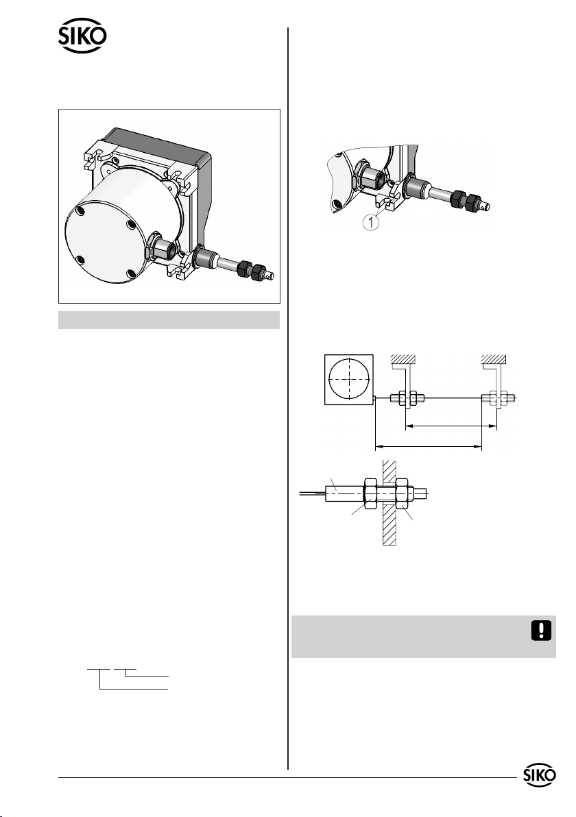
Abb. 1: Montage
Messbereich
max. Auszugslänge
Abb. 2: Prüfung Auszugslänge
Seilaufnahme
Einstellmutter
Kontermutter
Seil beim Befestigen
nicht verdrehen!
DEUTSCH
1. Gewährleistungshinweise
Lesen Sie vor der Montage und der Inbetriebnahme
dieses Dokument sorgfältig durch. Beachten Sie zu
Ihrer eigenen Sicherheit und der Betriebssicherheit
alle Warnungen und Hinweise.
Ihr Produkt hat unser Werk in geprüftem und be-
triebsbereitem Zustand verlassen. Für den Betrieb
gelten die angegeben Spezifikationen und die
Angaben auf dem Typenschild als Bedingung.
Garantieansprüche gelten nur für Produkte der
Firma SIKO GmbH. Bei dem Einsatz in Verbindung
mit Fremdprodukten besteht für das Gesamtsystem
kein Garantieanspruch.
Reparaturen dürfen nur im Werk vorgenommen
werden. Für weitere Fragen steht Ihnen die Firma
SIKO GmbH gerne zur Verfügung.
2. Identifikation
Das Typenschild zeigt den Gerätetyp mit Varianten-
nummer. Die Lieferpapiere ordnen jeder Varianten-
nummer eine detaillierte Bestellbezeichnung zu.
z.B. SG32-0023
Varianten-Nr.
Geräte-Typ
3. Mechanische Montage
Die Montage darf nur gemäß der angegebenen IP-
Schutzart vorgenommen werden. Das System muss
ggfs. zusätzlich gegen schädliche Umwelteinflüs-
•
•
•
•
se, wie z.B. Spritzwasser, Staub, Schläge, Tempe-
ratur geschützt werden.
Der Seilzuggeber ist ein hochwertiges Messsystem
für den Anbau auf eine ebene Montagefläche (Abb.
1).
Acht Langlöcher dienen zur Befestigung auf der
Montagefläche (1).
•
Benutzerinformation
SG32
Seilzuggeber
Nach der Befestigung des Seilzuggebers ist die
maximale Auszugslänge zu prüfen (siehe Abb.
2). Das Seilabschluss-Stück (Seilaufnahme,
Konter- und Einstellmutter) bzw. das Seil muss
dazu bis an die vorgesehene Befestigungsstelle
ausgezogen werden. Das Seil darf dabei nicht
verdreht werden.
•
Wenn die Auszugslänge den Anforderungen ent-
spricht kann die Seilaufnahme montiert werden
indem die Kontermuttern festgezogen werden.
Achtung! Das Seil darf nicht über die angegebene
max. Auszugslänge ausgezogen werden. Die Seil-
aufnahme darf nicht verdreht werden.
Handhabung des Seils
Das Seil muss lotrecht zum Seilausgang geführt
werden (siehe Abb. 2).
Das Seil darf nicht lose zurückschnellen, es muss
in jeder Situation und Bewegung, durch die Feder-
kraft der Seiltrommel, gespannt sein.
•

2 SG32 Datum 10.06.2010 Art.Nr. 85391 Änd. Stand 151/10
Abb. 7: Montage der Seilverlängerung
Abb. 3: Belüftungsöffnungen
Abb. 4: Belüftung geschlossen
Abb. 5: Belüftung geöffnet
Abb. 6: Seilverlängerung, Umlenkrolle
Seilverlängerung
Seilzuggeber
Umlenkrolle
Messbereich
Für eine korrekte Funktion darf das Seil nicht ge-
quetscht oder geknickt werden.
Belüftungsöffnungen
Falls erforderlich, kann das Seilzuggebergehäuse
mittels vier drehbaren Verschlüssen "geöffnet"
oder "geschlossen" werden (siehe Abb. 3 und 4).
Durch diese Öffnungen kann eindringendes Wasser
(Feuchtigkeit) abfließen.
Die Montage der Seilverlängerung erfolgt durch
Aufstecken des Anschlussstückes (3) auf die
Schraubverbindung (1). Mittels eingepresster
Spannhülse (2) werden beide Teile formschlüssig
miteinander verbunden.
Seilverlängerung (Zubehör)
Falls erforderlich kann eine Seilverlängerung ein-
gesetzt werden.
Achtung! Durch eine Seilverlängerung kann der
eigentliche Messbereich jedoch nicht vergrößert
werden. Die maximale Auszugslänge darf nicht
überschritten werden.
Umlenkrolle (Zubehör)
Wenn das Seil nicht lotrecht zum Seilausgang be-
festigt werden kann, ermöglicht der Einsatz einer
Umlenkrolle den Auszug in jede beliebige Richtung
(siehe Abb. 6).
Die Umlenkrolle muss parallel zum Seil montiert
werden.
Starke Schmutzbildung ist im Bereich der Umle-
krolle zu vermeiden, Die Funktion muss in regel-
mässigen Abständen kontrolliert werden.
Achtung! Bei Verwendung von Seilverlängerungen
ist darauf zu achten, dass das Verbindungsstück
nicht über die Umlenkrolle geführt werden kann.
4. Elektrischer Anschluss
Anschlussverbindungen dürfen nicht unter
Spannung geschlossen oder gelöst werden!!
Verdrahtungsarbeiten dürfen nur spannungslos
erfolgen.
Vor dem Einschalten sind alle Leitungsanschlüsse
und Steckverbindungen zu überprüfen.
Sicherheitshinweise:
Wenn durch den Ausfall oder eine Fehlfunktion
des Gebers eine Gefährdung von Mensch oder eine
Beschädigung von Betriebseinrichtungen nicht
auszuschließen ist, so muss dies durch geeignete
Sicherheitsmaßnahmen wie Schutzvorrichtungen
oder Endschalter usw. verhindert werden, bzw.
muss das Gerät außer Betrieb gesetzt und gegen
unbeabsichtigtes Einschalten gesichert sein.
Hinweise zur Störsicherheit
Alle Anschlüsse sind gegen äußere Störeinflüsse
geschützt. Der Einsatzort ist aber so zu wählen,
dass induktive oder kapazitive Störungen nicht
auf das Gerät oder deren Anschlussleitungen
einwirken können! Durch geeignete Kabelfüh-
rung und Verdrahtung können Störeinflüsse (z.B.
•
•
•
•
•
•
SG32 Datum 10.06.2010 Art.Nr. 85391 Änd. Stand 151/10 3
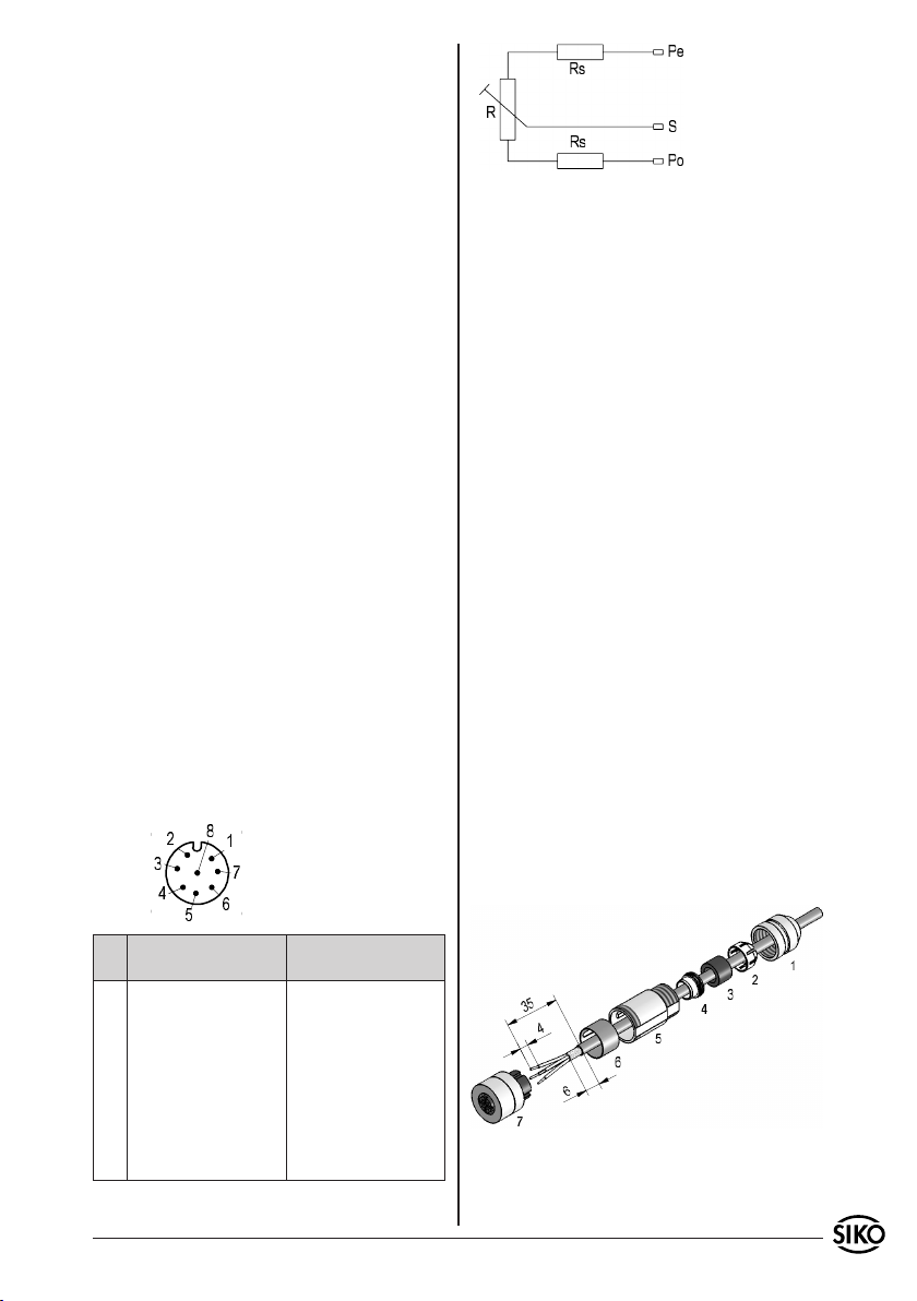
Ansichtseite = Steckseite
Rs = Serienimpedanz
R = Potentiometer
Abb. 8: Gegenstecker
von Schaltnetzteilen, Motoren, getakteten Reg-
lern oder Schützen) vermindert werden.
Erforderliche Maßnahmen:
Nur geschirmtes Kabel verwenden. Den Kabel-
schirm beidseitig auflegen. Litzenquerschnitt der
Leitungen max. 0,75mm².
Die Verdrahtung von Abschirmung und Masse (0V)
muss sternförmig und großflächig erfolgen. Der An-
schluss der Abschirmung an den Potentialausgleich
muss großflächig (niederimpedant) erfolgen.
Das System muss in möglichst großem Abstand von
Leitungen eingebaut werden, die mit Störungen
belastet sind; ggfs. sind zusätzliche Maßnahmen
wie Schirmbleche oder metallisierte Gehäuse
vorzusehen. Leitungsführungen parallel zu Ener-
gieleitungen vermeiden.
Schützspulen müssen mit Funkenlöschgliedern
beschaltet sein.
Leitungsführung parallel zu Energieleitungen ist
zu vermeiden.
Metallische Teile des Gebergehäuses müssen
gemäß den EMV-Bestimmungen geerdet sein und
dürfen nicht potentialfrei montiert werden.
Spannungsversorgung
Die Spannungsversorgung ist u.a. den Lieferpapie-
ren oder dem Typenschild zu entnehmen.
Spannungsversorgung ≤ 30VDC
Belastbarkeit < 1W
4.1 Anschlussbelegung
Potentiometer 8-pol. Stiftkontakt.
•
•
•
•
•
•
5. Einstellung und Abgleich
5.1 Einrichtung Potentiometer
Nach ordnungsgemäßem Anschluss zeigt das Gerät
beim Einschalten der Betriebsspannung den aktu-
ellen Istwert.
Der Messbereich des Potentiometers erstreckt sich
über die gesamte Auszugslänge des Seils. Im Werk
wird für die Auszugslänge 0mm (vollständig ein-
gezogen) der Potentiometer auf Minimalwert ein-
gestellt.
6. Inbetriebnahme
Bitte beachten Sie die Hinweise auf ordnungsge-
mäßen mechanischen und elektrischen Anschluss
in Kapitel 4. Nur dann sind die Voraussetzungen
für eine problemlose Inbetriebnahme und ein-
wandfreien Betrieb gegeben.
Prüfen Sie vor der Inbetriebnahme nochmals auf:
korrekte Polung der Betriebsspannung
korrekten Anschluss der Kabel
einwandfreie Montage des Geräts
7. Zubehör Anschluss-Stecker
Bei SIKO als Zubehör unter Art.Nr. 83525 er-
hältlich. Litzenquerschnitt der Leitungen max.
0,5mm². Kabeldurchlass: 6-8mm.
Bei der Steckermontage bitte schrittweise vor ge-
hen (siehe Abb. 8):
•
•
•
Pin Belegung
Potentiometer 1
Belegung
Potentiometer 2
1 Po Anfangsstellung - - -
2 - - - Po Anfangsstellung
3 - - - S Schleifer
4 - - - Pe Endstellung
5 - - - - - -
6 Pe Endstellung - - -
7 S Schleifer - - -
8 - - - - - - Dichtring an Schirmring (4) montieren.
Teile 1 ... 6 über Kabelmantel schieben.
1.
2.

4 SG32 Datum 10.06.2010 Art.Nr. 85391 Änd. Stand 151/10
Kabel abmanteln (35mm), Leiter abisolieren
(4mm) und verzinnen.
Schirm (auf 6mm) kürzen und umlegen.
Litzen in Einsatz (7) schrauben (entsprechend
Anschlussplan).
Teile 2 ... 6 montieren. Schirm um Schirmring
(4) legen.
Druckschraube (1) mit Kupplungshülse (5)
verschrauben.
3.
4.
5.
6.
7.
SG32 Datum 10.06.2010 Art.Nr. 85391 Änd. Stand 151/10 5
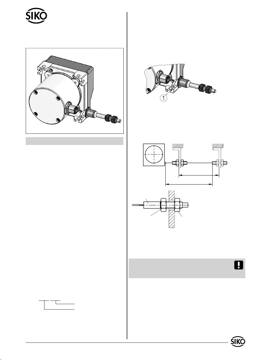
Fig. 1: Mounting
Wire insert
Setting nut
Lock nut
Do not distort wire
when fixing!
Measuring range
max. extension length
Fig. 2: Extension length check
User Information
SG32
Wire Actuated Encoder
ENGLISH
1. Warranty information
In order to carry out installation correctly, we
strongly recommend this document is read very
carefully. This will ensure your own safety and
the operating reliability of the device.
Your device has been quality controlled, tested
and is ready for use. Please observe all warnings
and information which are marked either directly
on the device or specified in this document.
Warranty can only be claimed for components
supplied by SIKO GmbH. If the system is used
together with other products, there is no warranty
for the complete system.
Repairs should be carried out only at our works.
If any information is missing or unclear, please
contact the SIKO sales staff.
2. Identification
Please check the particular type of unit and type
number from the identification plate. Type number
and the corresponding version are indicated in the
delivery documentation.
e.g. SG32-0023
version number
type of unit
3. Installation
For mounting, the degree of protection specified
must be observed. If necessary, protect the unit
•
•
•
•
against environmental influences such as sprayed
water, dust, knocks, extreme temperatures.
The wire actuated transmitter is a high quality
measurring device and should be mounted to a flat
surface (see fig. 1).
Use the eight elongated holes for fixing the unit
to the mounting surface (2).
•
Extend the wire up to the fixing point, ensuring
it is aligned and is not twisted. Tighten the lock
nut to fix the wire connector.
Attention! Do not extend the wire beyond the
max. allowable extension length and do not twist
wire insert.
Wire handling
Pull out the wire perpendicular to the wire outlet
(see fig. 2).
Do not let the wire go; in every position and during
every move the wire must be stretched by the cable
drum's spring force.
For correction function the wire must remain wit-
hout kinks or flattening.
•
After fixing the wire-actuated encoder, check the
maximum extension length (see fig. 2). Pull the
wire's end piece (wire insert, lock nut and setting
nut) or the wire to the indended fixing point. Do
not distort the wire!
•

6 SG32 Datum 10.06.2010 Art.Nr. 85391 Änd. Stand 151/10
Fig. 7: Mounting of the wire extension
Fig. 3: Aeration holes
Fig. 4: Aeration close
Fig. 5: Aeration open
Fig. 6: Extension wire, Guide roller
Extension wire
Wire actuated encoder
Guide rollers
Mesuring range
Extension wire (acessory)
If necessary an extension wire can be used.
Attention! By using an extension wire the maxi-
mum measuring length can not be altered. Make
sure that the maximum extension length is not
exceeded.
Guide rollers (accessory)
Are used for applications where wire actuated
transducer and wire cannot be mounted in one
line. Using guide rollers the wire can be pulled out
in any direction (see fig. 6).
Guide rollers must be mounted in line with the
wire.
Maintain cleanliness of guide rollers at all
times.
Attention! When using an extension wire make
sure that the wire connector dois not go over the
guide roller.
4. Electrical connection
Switch power off before any plug is inserted
or removed!!
Wiring must only be carried out with power off.
Check all lines and connections before switching
on the equipment.
Safety precautions:
If personal injury or damage to equipment is
possible should the encoder fail or malfunction,
this must be prevented by suitable safety precau-
tions such as protective devices or limit switches,
etc., or the device must be disabled and secured
against accidental switching on.
Interference an disortion
All connections are protected against the effects
of interference. The location should be selected
to ensure that no capacitive or inductive in-
terferences can affect the encoder or the con-
nection lines! Suitable wiring layout and choice
of cable can minimise the effects of interference
(eg. interference caused by SMPS, motors, cyclic
controls and contactors).
Necessary measures:
Only screened cable should be used. Screen should
be connected to earth at both ends. Wire cross
section is to be at least max. 0,75mm².
Wiring to screen and to ground (0V) must be via
•
•
•
•
•
•
•
•
Aeration holes
If needed, the wire-actuater's housing can be
"opened" or "closed" via 4 pivotabel closures (see
Fig. 3 and 4) for draining off water (humidity) in-
side the unit.
For mounting the wire extension: Push the con-
necting piece (3) onto the screw connector (1).
The press-fit clamping sleeve (2) will neatly join
both elements.
SG32 Datum 10.06.2010 Art.Nr. 85391 Änd. Stand 151/10 7
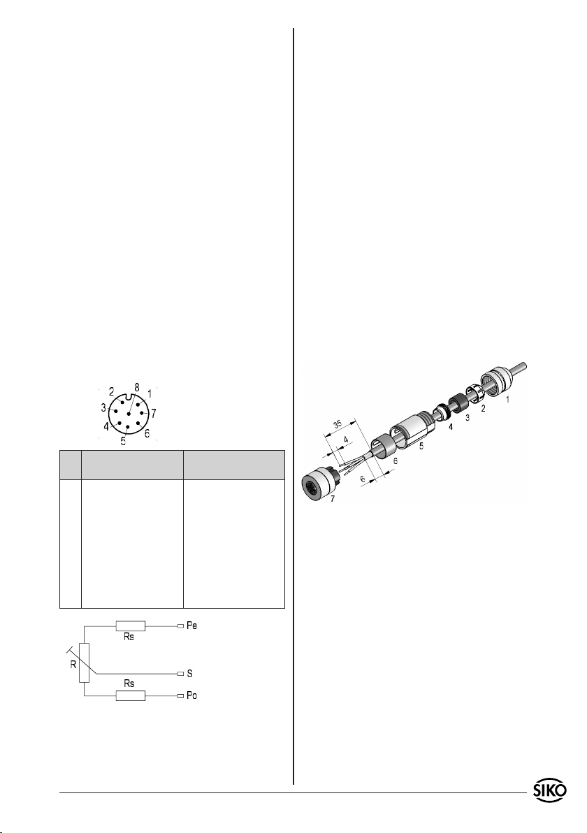
viewing side = plug-in-side
Fig. 8: Counter-plug
Rs = Series impedance
R = Potentiometer
a good earth point having a large surface area
for minimum impedance.
The unit should be positioned well away from
cables with interference; if necessary a protective
screen or metal housing must be provided. The
running of wiring parallel to the mains supply
should be avoided.
Contactor coils must be linked with spark sup-
pression.
The running of wiring parallel to the mains supply
should be avoided.
Metallic components of the transmitter housing
should be earthed according to local regulations
and should not be connected potential free.
Power supply
Supply voltage is indicated in the delivery docu-
mentation and on the identification plate.
Power supply ≤ 30VDC
Load capacity < 1W
4.1 Pin assignment
Potentiometer 8 pole plug pin.
•
•
•
•
The measuring range of the potentiometer is mat-
ched to the total pull-out length of the wire. Ex
works the potentiometers is adjusted to lowest
value for extension length 0mm (ie. for fully re-
traced wire).
6. Starting
Please ensure that the instructions given in chap-
ter 4 regarding mechanical and electrical connec-
tion are followed. This will ensure correct installa-
tion and the operating reliability of the device.
Before starting check again:
correct polarity of the supply voltage
correct cable connection
correct mounting of the device
7. Accessory connector
Available from SIKO as accessory art.no. 83525.
Wire cross section is to be at least max. 0,5mm².
Cable channel: 6-8mm.
Please proceed as follows (see fig. 8):
•
•
•
Pin Designation
Potentiometer 1
Designation
Potentiometer 2
1 Po Start point - - -
2 - - - Po Start point
3 - - - S Moving contact
4 - - - Pe End point
5 - - - - - -
6 Pe End point - - -
7 S Moving contact - - -
8 - - - - - -
5. Adjusment and alignement
5.1 Potentiometer setting
When correctly connected and switched on, the
unit displays the current actual value.
Mount seal to screen ring (4).
Slip parts 1 ... 6 over outer cable.
Dismantle cable (35mm), strip (4mm) and tin
conductor.
Shorten (except for 6mm) and turn down
screen.
Screw wires into socket (7) (follow connection
diagram).
Mount parts 2 ... 6. Place screen around screen
ring (4).
Screw pressing screw (1) and coupling sleeve(5)
together.
1.
2.
3.
4.
5.
6.
7.
8 SG32 Datum 10.06.2010 Art.Nr. 85391 Änd. Stand 151/10
SIKO GmbH
Werk / Factory:
Weihermattenweg 2
79256 Buchenbach-Unteribental
Postanschrift / Postal address:
Postfach 1106
79195 Kirchzarten
Telefon/Phone +49 7661 394-0
Telefax/Fax +49 7661 394-388
E-Mail info@siko.de
Internet www.siko.de
Service [email protected]
Other manuals for SG32
2
Table of contents
Languages:
Other Siko Media Converter manuals


Popular Media Converter manuals by other brands


Key Digital
Key Digital KD-CAT5XRCA Specifications

Elatec
Elatec TCP3 3.0.3.1 Technical manual

Danfoss
Danfoss FC 300 Design guide

Kaya Instruments
Kaya Instruments Komodo CoaXPress manual

JRC
JRC NJU26209 manual

METRObility Optical Systems
METRObility Optical Systems twister 2131-34-01 Installation & user guide


