A
Обзороборудования
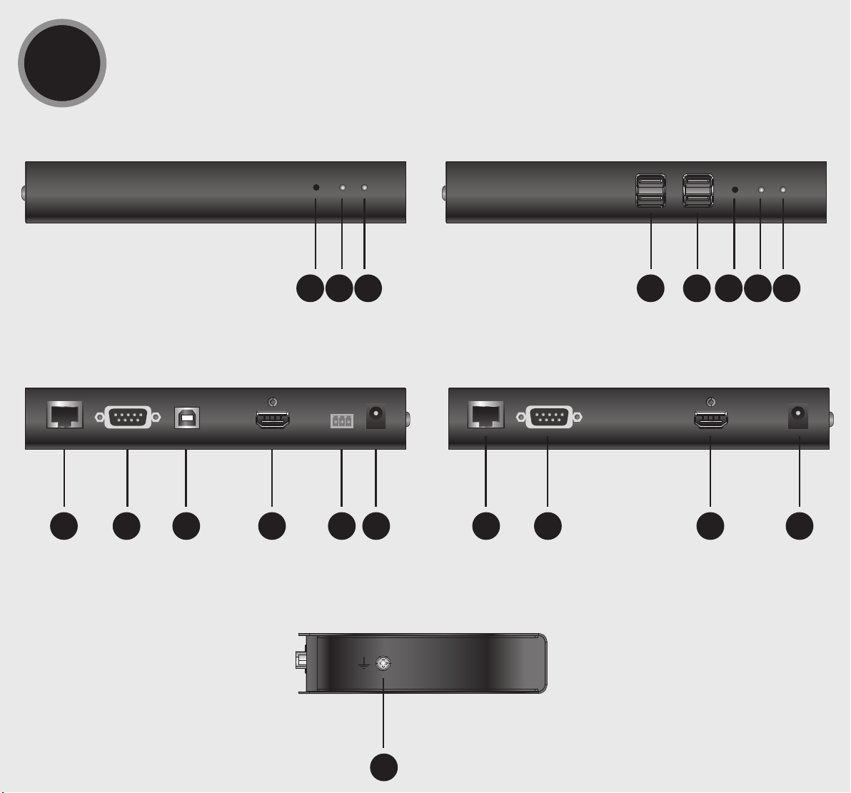
ПередняяпанельKE8900ST
1Кнопка сброса (утопленная кнопка)
2Индикатор LAN
3Индикатор питания
ЗадняяпанельKE8900ST
4Порт LAN
5Порт RS-232
6Порт USB Type-B
7Порт HDMI
83-контактный клеммник (вход
питания)
9Разъём питания
БоковаяпанельKE8900ST/KE8900SR
10 Заземляющий контакт
B
Установкаоборудования
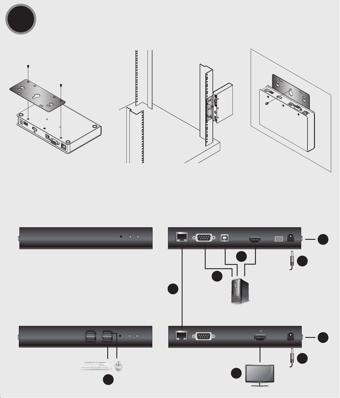
Монтажвстойке
1. Винтами из монтажного комплекта прикрепите монтажный кронштейн к нижней
части устройства (как показано на схеме выше).
2. Привинтите монтажный кронштейн к стойке в любом удобном месте.
Примечание. Для монтажа KE8900ST/KE8900SR следует использовать Комплект
стоечного монтажа повторителей ATEN VE-RMK 1U. Комплект
можно приобрести у местного дилера компании.
Монтажнастене
1. Винтами из монтажного комплекта прикрепите монтажный кронштейн к нижней
части устройства (как показано на схеме выше).
2. Для прикрепления устройства к стене, вверните болт в стену через
центральное отверстие для болта в монтажном кронштейне.
Установкасоединения«точка-точка»
Для установки прямого соединения между двумя устройствами выполните
следующее:
1 (Дополнительно) Подсоедините контакты заземления на KE8900ST и KE8900SR к
подходящим заземленным объектам с помощью заземляющих проводов.
2 Подсоедините прилагаемый кабель «USB/HDMI/KVM» к соответствующим портам
на компьютере и на KE8900ST. Для подключения KE8900ST (имеющего порт USB
Type-B) следует использовать разъем USB Type-B кабеля «USB/HDMI/KVM».
3 Подсоедините кабель Cat 5e/6 к портам LAN на KE8900ST и на KE8900SR.
4 Подсоедините USB-мышь/клавиатуру к передней панели KE8900SR, а HDMI-
монитор к задней панели KE8900SR.
5 Подключите адаптеры питания к электророзеткам, а затем подключите
выходы адаптеров к разъемам питания на KE8900ST и на KE8900SR. Также в
качестве входа питания на KE8900ST можно использовать клеммник питания,
подсоединив к нему провода в соответствии с маркировкой*.
6 (Дополнительно) Для управления последовательными устройствами
подключите разъем RS-232 на KE8900ST к последовательному порту
компьютера.
7 Включите компьютер.
Установкасетевогосоединения
Установка сетевого соединения с подключением нескольких устройств серии KE к единой
сети TCP/IP позволяет устанавливать соединение между консолями и компьютерами в
режимах «точка-точка», «точка-многоточка» и «многоточка-многоточка». Для установки
сетевого соединения нужно просто подсоединить кабель Cat 5e/6 не напрямую между
двумя устройствами серии KE (см. пункт 3), а к локальной сети*.
Свойстваэкранногоменю*
Экранное меню, управляемое с помощью клавиатуры и мыши, представляет
собой программное меню, предназначенное для настройки и управления работой
устройств KE. Настройка приемника и передатчика осуществляется из экранного
меню приемника. После того как передатчик и приемник обнаружат друг друга (через
прямое или сетевое соединение), экранное меню приемника можно использовать
для контроля и настройки параметров обоих устройств. Чтобы вызвать экранное
меню, дважды нажмите клавишу [Scroll Lock]. Сведения о пароле приведены в меню
«Свойства экранного меню». Для выхода из экранного меню нажмите [ESC]; затем
выберите «Выход» или «Назад к видео», либо вернитесь в главное меню. После
выхода из экранного меню появляется экран компьютера.
№ Пункт Описание
1Станция
пользователя Выберите эту опцию, введите пароль и нажмите «Настроить»
для входа в меню «Станция пользователя».
2 Передатчик Выберите эту опцию, введите пароль и нажмите «Настроить»
для входа в меню «Передатчик».
3Настройки
пользователя Выберите эту опцию, введите пароль и нажмите «Настроить»
для входа в меню «Настройки пользователя».
4Настроить После ввода пароля нажмите эту кнопку, чтобы войти в
выбранное меню настройки.
Примечание. Пароль для входа в выбранное меню настройки:
password
. Имя
пользователя и пароль, вводимые на странице «Вход в систему» в
режиме матрицы:
administrator / password
.
* Для получения дополнительных сведений загрузите руководство пользователя
устройств серии KE с сайта www.aten.com/download.
Повторитель (передатчик) KE8900ST Slim HDMI KVM over IP / Повторитель (приемник) KE8900SR Slim HDMI KVM over IP www.aten.com
ПередняяпанельKE8900SR
1Периферийные USB-порты
2USB-порты (консоль)
3Кнопка сброса (утопленная кнопка)
4Индикатор LAN
5Индикатор питания
ЗадняяпанельKE8900SR
6Порт LAN
7Порт RS-232
8Порт HDMI
9Разъём питания
A
Revisione Hardware
Vista anteriore KE8900ST
1Ripristina (pulsante incassato)
2LAN LED
3LED alimentazione
Vista posteriore KE8900ST
4Porta LAN
5Porta RS-232
6Porta USB Tipo-B
7Porta HDMI
8Morsetto a 3 poli (ingresso di
alimentazione)
9Connettore di alimentazione
KE8900ST / KE8900SR vista laterale
10 Terminale di massa
B
Installazione dell'hardware
Montaggio in rack
1. Utilizzare le viti fornite con il kit di montaggio per avvitare la staffa di montaggio sul
fondo dell'unità (fare riferimento ai disegni illustrati sopra).
2. Avvitare la staffa di montaggio in qualsiasi posizione comoda sul rack.
Nota: Il KE8900ST / KE8900SR può essere installato nel kit di montaggio estensore rack
ATEN VE-RMK 1U. Per acquistare questo kit, contattare il rivenditore locale.
Montaggio a parete
1. Utilizzare le viti fornite con il kit di montaggio per avvitare la staffa di montaggio sul
fondo dell'unità (fare riferimento ai disegni illustrati sopra).
2. Utilizzare il foro della vite centrale della staffa di montaggio per montare l'unità su una
parete.
Installazione punto-punto
Per un'installazione diretta dell'unità all'unità, effettuare le seguenti operazioni
1(Opzionale) Collegare i terminali di messa a terra del KE8900ST e del KE8900SR a un
oggetto con messa a terra adeguato utilizzando fili di messa a terra.
2Collegare il cavo USB HDMI KVM fornito con questo pacchetto tra un computer e la
centralina KE8900ST. Utilizzare l'estremità USB Type-B del cavo KVM HDMI USB per il
KE8900ST in quanto dispone di una porta USB Type-B.
3Collegare un cavo Cat 5e/6 tra le porte LAN del KE8900ST e del KE8900SR.
4Collegare un mouse/tastiera USB al pannello anteriore del monitor KE8900SR e HDMI
al pannello posteriore del KE8900SR.
5Collegare gli adattatori di alimentazione alle prese di corrente, quindi collegare le altre
estremità rispettivamente alle prese di alimentazione del KE8900ST e del KE8900SR.
Per il KE8900ST, è possibile scegliere di utilizzare la morsettiera per l'ingresso di
alimentazione e collegare i cavi di alimentazione in base all'icona.*
6(Opzionale) Per il controllo di dispositivi seriali, collegare la porta seriale RS-232 del
KE8900ST a una porta seriale del computer.
7Accendere il computer.
Impostazione di un'installazione LAN
La configurazione delle unità su una rete consente operazioni da punto a punto, da
punto a multipunto, dal computer multipunto a multipunto, a funzionamento console,
collegando più dispositivi della serie KE sulla stessa LAN TCP / IP. Per configurare
un'installazione LAN, è sufficiente collegare il cavo Cat 5e/6 (nel passaggio 3) alla rete
anziché direttamente tra due dispositivi della serie KE.*
Opzioni OSD*
La visualizzazione su schermo è un'applicazione basata su menu basata su tastiera e
mouse per gestire il controllo e la configurazione delle operazioni di KE. Entrambe le
unità trasmettitore e ricevitore sono configurate dal menu OSD sul ricevitore. Una volta
che le unità trasmittente e ricevente si sono scoperte reciprocamente (tramite una rete o
una connessione diretta) è possibile utilizzare il menu OSD del ricevitore per mantenere
la configurazione e il controllo della configurazione. Per richiamare l'OSD, toccare il
tasto [Scroll Lock] due volte. Le informazioni sulla password sono fornite in Opzioni OSD.
Per uscire dall'OSD, premere il tasto [Esc]; fare clic su Disconnetti o Torna al video dal
menu OSD; o tornare al menu principale OSD. Quando il menu OSD viene chiuso, viene
visualizzata la schermata del computer.
N. Articolo Descrizione
1 Stazione utente
Selezionare questo pulsante di opzione, inserire la password e cliccare
su Configura per accedere alla schermata di configurazione della
Stazione utente.
2 Trasmettitore
Selezionare questo pulsante di opzione, inserire la password e cliccare
su Configura per accedere alla schermata di configurazione del
trasmettitore.
3Preferenze
utente
Selezionare questo pulsante di opzione, inserire la password e cliccare
su Configura per accedere alla schermata di configurazione del
Preferenze utente.
4 Configurazione Dopo aver inserito una password, fare clic su questo pulsante per
accedere alla schermata di configurazione selezionata.
Nota: La password per accedere alle schermate di configurazione OSD è:
password
. Il
nome utente / password per accedere alla pagina di accesso al sistema in modalità
Matrix sono:
amministratore / password
.
* Scaricare il Manuale dell'utente della serie KE dal sito www.aten.com/download per
ulteriori informazioni.
KE8900ST Slim HDMI estensore KVM su IP (trasmettitore) / KE8900SR Slim HDMI estensore KVM su IP (ricevitore) www.aten.com
Vista anteriore KE8900SR
1Porte periferiche USB
2Porte USB (consolle)
3Ripristina (pulsante incassato)
4LAN LED
5LED alimentazione
Vista posteriore KE8900SR
6Porta LAN
7Porta RS-232
8Porta HDMI
9Connettore di alimentazione
A
Revisión del hardware
Vista frontal del KE8900ST
1Restablecer (botón empotrado)
2LED LAN
3LED de alimentación
Vista posterior del KE8900ST
4Puerto LAN
5Puerto RS-232
6Puerto USB tipo B
7Puerto HDMI
8Bloque de terminales de 3 polos
(entrada de corriente)
9Conector de alimentación
Vista lateral del KE8900ST / KE8900SR
10 Terminal de toma de tierra
B
Instalación de hardware
Montaje en rack
1. Utilice los tornillos provistos con el kit de montaje para atornillar el soporte de montaje
a la parte inferior de la unidad (consulte los dibujos que se muestran arriba).
2. Atornille el soporte de montaje a cualquier parte del bastidor.
Nota: El KE8900ST / KE8900SR puede instalarse en el kit de montaje en bastidor para
el extensor ATEN VE-RMK 1U. Para comprar este kit contacte con su distribuidor
local.
Montaje en pared
1. Utilice los tornillos provistos con el kit de montaje para atornillar el soporte de montaje
a la parte inferior de la unidad (consulte los dibujos que se muestran arriba).
2. Utilice el orificio de tornillo central del soporte de montaje para montar la unidad en
una pared.
Instalación punto a punto
Para una instalación directa de unidad a unidad, haga lo siguiente
1(Opcional) Conecte los terminales de conexión a tierra del KE8900ST y del KE8900SR a
un objeto conectado adecuadamente a tierra utilizando cables de conexión a tierra.
2Conecte el cable USB HDMI KVM proporcionado con este paquete y el KE8900ST.
Utilice el USB tipo B del cable USB HDMI KVM para el KE8900ST ya que tiene un
puerto USB tipo B.
3Conecte un cable Cat 5e/6 entre los puertos LAN del KE8900ST y del KE8900SR.
4Conecte un ratón/teclado USB al panel frontal del KE8900SR y el monitor HDMI al
panel posterior del KE8900SR.
5Enchufe los adaptadores de corriente en las tomas de corriente; luego conecte los
otros extremos a las tomas de corriente del KE8900ST y del KE8900SR. Para KE8900ST,
puede optar por usar el bloque de terminales para la entrada de corriente y conectarlo
de acuerdo con el icono.*
6(Opcional) Para controlar dispositivos en serie, conecte el puerto serie RS-232 del
KE8900ST a un puerto serie del ordenador.
7Encienda el ordenador.
Configuración de una instalación LAN
Varios dispositivos en la misma red permiten la operación ordenador a consola punto a
punto, punto a multipunto y multipunto a multipunto conectando múltiples dispositivos
KE Series en la misma LAN TCP/IP. Para configurar una instalación LAN, simplemente
conecte el cable Cat 5e/6 (en el paso 3) a la red en lugar de conectarlo entre dos
dispositivos KE Series.*
Opciones del OSD*
El menú en pantalla es una aplicación controlada por teclado y ratón para llevar a cabo el
control y la configuración de las operaciones del KE. Tanto el transmisor como el receptor
se configuran desde el menú OSD del receptor. Una vez que las unidades transmisora y
receptora se han descubierto (a través de una red o conexión directa) puede usar el menú
OSD del receptor para llevar a cabo la configuración y el control de la configuración. Para
abrir el OSD, toque la tecla [Bloq Despl] dos veces. La información de la contraseña se
proporciona en las Opciones del OSD. Para salir del OSD, presione la tecla [Esc]; haga clic
en Logout (Cerrar sesión) o Back to Video (Volver al vídeo) desde el menú OSD; o regrese
al menú principal del OSD. Al cerrar el menú OSD, aparecerá la pantalla del ordenador.
Nº Artículo Descripción
1Estación de
usuario
Marque este botón de selección, introduzca la contraseña y haga clic en
Configurar para entrar en la pantalla de configuración de la estación de
usuario.
2 Transmisor Marque este botón de selección, introduzca la contraseña y haga clic en
Configurar para entrar en la pantalla de configuración del transmisor.
3Preferencias
de usuario
Marque este botón de selección, introduzca la contraseña y haga clic en
Configurar para entrar en la pantalla de configuración de las preferencias.
4 Configurar Después de escribir la contraseña, haga clic en este botón para entrar en
la pantalla de configuración seleccionada.
Nota: La contraseña para entrar en las pantallas de configuración del OSD es:
contraseña
.
El nombre de usuario / contraseña para entrar en la página de inicio de sesión del
sistema en el modo matriz es:
administrador / contraseña
.
* Descargue el Manual del usuario del KE Series en www.aten.com/download para más
información.
Extensor KVM sobre IP KE8900ST Slim HDMI (transmisor) / Extensor KVM sobre IP KE8900SR Slim HDMI (receptor) www.aten.com
Vista frontal del KE8900SR
1Puertos periféricos USB
2Puertos USB (consola)
3Restablecer (botón empotrado)
4LED LAN
5LED de alimentación
Vista posterior del KE8900SR
6Puerto LAN
7Puerto RS-232
8Puerto HDMI
9Conector de alimentación
A
Hardware Übersicht
KE8900ST – Ansicht von vorne
1Reset (vertiefte Taste)
2LAN LED
3Betriebsanzeige-LED
KE8900ST – Ansicht von hinten
4LAN-Port
5RS-232-Port
6USB Typ-B Port
7HDMI-Anschluss
83-poliger Anschlussblock
(Stromeingang)
9Netzanschluss
KE8900ST / KE8900SR Seitenansicht
10 Erdungsklemme
B
Hardwareinstallation
Rack-Montage
1. Verwenden Sie die mit dem Montageset gelieferten Schrauben, um die
Montagehalterung an der Unterseite des Geräts zu befestigen (siehe Zeichnungen
oben).
2. Befestigen Sie die Montagehalterung mittels Schrauben an einer geeigneten Stelle im Rack.
Hinweis: Der KE8900ST / KE8900SR kann in das ATEN VE-RMK 1U Extender Rack-
Montageset eingebaut werden. Um dieses Set zu kaufen, wenden Sie sich bitte
an Ihren Händler vor Ort.
Wandmontage
1. Verwenden Sie die mit dem Montageset gelieferten Schrauben, um die Montagehalterung
an der Unterseite des Geräts zu befestigen (siehe Zeichnungen oben).
2. Verwenden Sie die mittlere Schraubenbohrung der Montagehalterung, um das Gerät
an einer Wand zu befestigen.
Punkt-zu-Punkt-Installation
Für eine direkte Installation von Gerät zu Gerät gehen Sie wie folgt vor
1(Optional) Verbinden Sie die Erdungsanschlüsse des KE8900ST und KE8900SR mit
einem geeigneten geerdeten Objekt über Erdungsleitungen.
2Schließen Sie das mitgelieferte USB-HDMI-KVM-Kabel zwischen einem Computer und
dem KE8900ST an. Bitte verwenden Sie das USB Typ-B Ende des USB-HDMI-KVM-
Kabels für den KE8900ST, da es über einen USB Typ-B Port verfügt.
3Schließen Sie ein Cat 5e/6-Kabel zwischen den LAN-Ports von KE8900ST und
KE8900SR an.
4Schließen Sie eine USB-Maus/Tastatur an die Frontplatte des KE8900SR und einen
HDMI-Monitor an die Rückseite des KE8900SR an.
5Stecken Sie die Netzteile in die Steckdosen, dann die anderen Enden in die
Netzbuchsen des KE8900ST und KE8900SR. Beim KE8900ST können Sie den
Anschlussblock für die Spannungsversorgung verwenden und die Stromkabel
entsprechend dem Symbol anschließen.*
6(Optional) Zur Steuerung serieller Geräte verbinden Sie die serielle Schnittstelle RS-232
des KE8900ST mit einer seriellen Schnittstelle des Computers.
7Schalten Sie den Computer ein.
Einrichten einer LAN-Installation
Die Einrichtung der Geräte in einem Netzwerk ermöglicht Punkt-zu-Punkt-, Punkt-
zu-Multipunkt- und Multipunkt-zu-Multipunkt Computer den Konsolenbetrieb durch
Anschluss mehrerer Geräte der KE-Serie an dasselbe TCP/IP-LAN. Um eine LAN-Installation
einzurichten, verbinden Sie einfach das Cat 5e/6-Kabel (in Schritt 3) mit dem Netzwerk
und nicht direkt zwischen zwei Geräten der KE-Serie.*
OSD-Optionen*
Das On-Screen-Display ist eine menügesteuerte Anwendung zur Steuerung und
Konfiguration von KE-Operationen. Sowohl die Transmitter- als auch die Empfängereinheit
werden über das OSD-Menü am Empfänger konfiguriert. Sobald sich die Transmitter-
und Empfängereinheiten gegenseitig entdeckt haben (über ein Netzwerk oder eine
direkte Verbindung), können Sie das OSD-Menü des Empfängers verwenden, um die
Konfiguration und Steuerung der Einrichtung vorzunehmen. Um das OSD aufzurufen,
tippen Sie zweimal auf die Taste [Rollen]. Passwortinformationen finden Sie unter OSD-
Optionen. Um das OSD zu verlassen, drücken Sie die Taste [Esc], klicken Sie im OSD-Menü
auf Abmelden oder Zurück zu Video oder kehren Sie zum OSD-Hauptmenü zurück. Wenn
das OSD-Menü verlassen wird, erscheint der Bildschirm des Computers.
Nr. Element Beschreibung
1 Benutzerstation
Markieren Sie dieses Optionsfeld, geben Sie das Passwort ein, und
klicken Sie auf Konfigurieren, um den Konfigurationsbildschirm
der Benutzerstation aufzurufen.
2 Transmitter
Markieren Sie dieses Optionsfeld, geben Sie das Passwort ein, und
klicken Sie auf Konfigurieren, um den Konfigurationsbildschirm
des Transmitters aufzurufen.
3 Benutzereinstellungen
Markieren Sie dieses Optionsfeld, geben Sie das Passwort ein, und
klicken Sie auf Konfigurieren, um den Konfigurationsbildschirm
der Benutzereinstellungen aufzurufen.
4 Konfigurieren
Nachdem Sie ein Passwort eingegeben haben, klicken
Sie auf diese Schaltfläche, um den ausgewählten
Konfigurationsbildschirm aufzurufen.
Hinweis: Das Passwort für den Zugang zu den OSD-Konfigurationsbildschirmen lautet:
password
. Der Benutzername / das Passwort für den Zugang zur System
Anmeldeseite im Matrix-Modus lautet:
administrator / password
.
* Laden Sie das Benutzerhandbuch der KE-Serie von www.aten.com/download herunter,
um weitere Informationen zu erhalten.
KE8900ST Slim HDMI KVM over IP Extender (Transmitter) / KE8900SR Slim HDMI KVM over IP Extender (Empfänger) www.aten.com
KE8900SR – Ansicht von vorne
1USB-Peripherieports
2USB-Ports (Konsole)
3Reset (vertiefte Taste)
4LAN LED
5Betriebsanzeige-LED
KE8900SR – Ansicht von hinten
6LAN-Port
7RS-232-Port
8HDMI-Anschluss
9Netzanschluss
A
Présentation du matériel
Vue de devant du KE8900ST
1Reset (Bouton encastré)
2LED LAN
3LED d'alimentation
Vue de derrière du KE8900ST
4Port LAN
5Port RS-232
6Port USB Type B
7Port HDMI
8Bloc Terminal 3-Pôles (Entrée électrique)
9Fiche d'alimentation
Vue latérale KE8900ST / KE8900SR
10 Borne de terre
B
Installation matérielle
Montage en rack
1. Utilisez les vis fournies avec le kit de montage pour visser le support de montage au
bas de l'appareil (Reportez-vous aux dessins ci-dessus).
2. Vissez le support de montage dans un quelconque emplacement pratique sur le rack.
Remarque : Le KE8900ST / KE8900SR peut être installé dans le Kit de Montage en Rack
de l’Extenseur ATEN VE-RMK 1U. Pour acheter ce kit, veuillez contacter votre
vendeur.
Montage mural
1. Utilisez les vis fournies avec le kit de montage pour visser le support de montage au bas
de l'appareil (Reportez-vous aux dessins ci-dessus).
2. Utilisez le trou de vis central du support de montage pour monter l'appareil sur un mur.
Installation Point-à-Point
Pour une installation directe d’unité à unité, faites comme suit:
1(Optionnel) Connectez les terminaux de terre du KE8900ST et du KE8900SR à un objet
correctement mis à terre en utilisant des câbles de terre.
2Connectez le câble USB HDMI KVM fourni avec cet emballage entre un ordinateur
et le KE8900ST. Veuillez utiliser le bout USB Type-B du câble USB HDMI KVM pour le
KE8900ST car il a un port USB Type B.
3Connectez un câble Cat 5e/6 entre les ports LAN du KE8900ST et du KE8900SR.
4Connectez un clavier/souris USB sur le panneau avant du KE8900SR et le moniteur
HDMI du panneau arrière du KE8900SR.
5Branchez les adaptateurs électriques dans les prises d’alimentation; branchez
ensuite les autres bouts respectivement dans les fiches électriques du KE8900ST et
du KE8900SR. Pour KE8900ST, vous pouvez choisir d’utiliser un bloc terminal pour
l’alimentation et de connecter les fils électriques respectivement selon l’icône.*
6(Optionnel) Pour le contrôle des périphériques, connectez le port sériel RS-232 sur le
KE8900ST à un port sériel sur l’ordinateur.
7Allumez l'ordinateur.
Paramétrer une Installation LAN
Paramétrer les unités sur un réseau permet à un ordinateur point-à-point, point-à-
multipoint et multipoint-à-multipoint de contrôler une opération en connectant de
multiples périphériques KE sur le même LAN TCP/IP. Pour paramétrer une installation
LAN, connectez simplement le câble Cat 5e/6 (dans l’étape 3) sur le réseau au lieu de
directement entre deux périphériques KE.*
Options OSD*
L’Affichage Sur Ecran est une application à menus contrôlée par un clavier et une souris
pour gérer le contrôle et la configuration des opérations KE. Les unités du transmetteur
et du récepteur sont configurées depuis le menu OSD sur le récepteur. Une fois que le
transmetteur et le récepteur se sont découverts mutuellement (depuis un réseau ou en
connexion directe), vous pouvez utiliser le menu OSD du récepteur pour conserver la
configuration et le contrôle de l’installation. Pour appeler l’OSD, tapotez deux fois sur la
touche [Scroll Lock]. L’information du mot de passe se trouve dans les Options OSD. Pour
quitter l’OSD, pressez la touche [Esc]; cliquez sur Déconnexion ou Retour à la Vidéo depuis
le menu OSD; ou retournez au Menu Principal OSD. Lorsque vous sortez du Menu OSD,
l’écran de l’ordinateur apparaîtra.
Non. Elément Description
1Station
Utilisateur
Sélectionnez ce bouton de radio, entrez le mot de passe et cliquez
sur Configurer pour entrer dans l’écran de configuration de la Station
Utilisateur.
2 Transmetteur Sélectionnez ce bouton de radio, entrez le mot de passe et cliquez sur
Configurer pour entrer dans l’écran de configuration du Transmetteur.
3Préférences
Utilisateur
Sélectionnez ce bouton de radio, entrez le mot de passe et cliquez sur
Configurer pour entrer dans l’écran de configuration des Préférences
Utilisateur.
4 Configurer Après avoir entré un mot de passe, cliquez sur ce bouton pour entrer
dans l’écran de configuration sélectionné.
Remarque : Le mot de passe pour entrer dans l’écran de configuration OSD est:
Mot de
passe
. Le nom utilisateur/mot de passe pour entrer dans la page Connexion
au Système dans le Mode Matrice est:
administrateur / mot de passe
.
* Téléchargez le Mode d’Emploi des Séries KE depuis www.aten.com/download pour plus
d'informations.
Extenseur KE8900ST Slim HDMI KVM over IP (Transmetteur) / Extenseur KE8900SR Slim HDMI KVM over IP (Récepteur) www.aten.com
Vue de devant du KE8900SR
1Ports périphériques USB
2Ports USB (Console)
3Reset (Bouton encastré)
4LED LAN
5LED d'alimentation
Vue de derrière du KE8900SR
6Port LAN
7Port RS-232
8Port HDMI
9Fiche d'alimentation
A
Hardware Review
KE8900ST Front View
1Reset (Recessed Button)
2LAN LED
3Power LED
KE8900ST Rear View
4LAN Port
5RS-232 Port
6USB Type-B Port
7HDMI Port
83-Pole Terminal Bloc (Power Input)
9Power Jack
KE8900ST / KE8900SR Side View
10 Grounding Terminal
B
Hardware Installation
Rack Mounting
1. Use the screws provided with the mounting kit to screw the mounting bracket to the
bottom of the unit (Refer to the drawings shown above).
2. Screw the mounting bracket to any convenient location on the rack.
Note: The KE8900ST / KE8900SR can be installed in the ATEN VE-RMK 1U Extender Rack
Mount Kit. To purchase this kit contact your local dealer.
Wall Mounting
1. Use the screws provided with the mounting kit to screw the mounting bracket to the
bottom of the unit (Refer to the drawings shown above).
2. Use the mounting bracket’s center screw hole to mount the unit on a wall.
Point-to-Point Installation
For a direct unit to unit installation, do the following
1(Optional) Connect the grounding terminals of KE8900ST and KE8900SR to a suitable
grounded object using grounding wires.
2Connect the USB HDMI KVM Cable provided with this package between a computer
and the KE8900ST. Please use the USB Type-B end of the USB HDMI KVM Cable for
the KE8900ST as it has a USB Type-B port.
3Connect a Cat 5e/6 cable between the LAN ports of KE8900ST and KE8900SR.
4Connect a USB mouse/keyboard to the front panel of the KE8900SR and HDMI
monitor to the rear panel of the KE8900SR.
5Plug the power adapters into power sockets; then plug the other ends respectively
into KE8900ST and KE8900SR’s power jacks. For KE8900ST, you can choose to use the
terminal block for power input and connect the power wires according to the icon.*
6(Optional) For control of serial devices, connect the RS-232 serial port on the KE8900ST
to a serial port on the computer.
7Power on the computer.
Setting up a LAN Installation
Setting up the units on a network allows point-to-point, point-to-multipoint, and
multipoint-to-multipoint computer to console operation by connecting multiple KE Series
devices on the same TCP/IP LAN. To set up a LAN installation, simply connect the Cat 5e/6
cable (in step 3) to the network instead of directly between two KE Series devices.*
OSD Options*
The On-Screen Display is a keyboard and mouse driven menu-based application to handle
control and configuration of KE operations. Both the transmitter and receiver units are
configured from the OSD menu on the receiver. Once the transmitter and receiver units
have discovered each other (over a network or direct connection) you can use the receiver's
OSD menu to maintain configuration and control of the setup. To invoke the OSD, tap the
[Scroll Lock] key twice. Password information is provided under OSD Options. To exit the
OSD, press the [Esc] key; click Logout or Back to Video from the OSD menu; or return to
the OSD Main menu. When the OSD menu exits, the computer’s screen will appear.
No. Item Description
1 User Station Select this radio button, enter the password, and click Configure to enter
the User Station configuration screen.
2 Transmitter Select this radio button, enter the password, and click Configure to enter
the Transmitter configuration screen.
3User
Preferences
Select this radio button, enter the password, and click Configure to enter
the User Preferences configuration screen.
4 Configure After entering a password, click this button to enter the selected
configuration screen.
Note: The password to enter the OSD configuration screens is:
password
. The username
/ password to enter the System Login page in Matrix Mode is:
administrator /
password
.
*Download the KE Series User Manual from www.aten.com/download for more
information.
KE8900ST Slim HDMI KVM over IP Extender (Transmitter) / KE8900SR Slim HDMI KVM over IP Extender (Receiver) www.aten.com
KE8900SR Front View
1USB Peripheral Ports
2USB Ports (Console)
3Reset (Recessed Button)
4LAN LED
5Power LED
KE8900SR Rear View
6LAN Port
7RS-232 Port
8HDMI Port
9Power Jack
B
* Please refer to http://www.aten.com/global/en/products/professional-audiovideo/
accessories/2x-ea12/#.WPROpmd-XIU for the installation of HDMI Lockpro
KE8900ST Package Contents
1 Slim HDMI KVM over IP Extender (Transmitter)
1 USB HDMI KVM Cable
1 Power Adapter
1 Mounting Kit
1 HDMI Lockpro*
1 User Instructions
KE8900SR Package Contents
1 Slim HDMI KVM over IP Extender (Receiver)
1 Power Adapter
1 Mounting Kit
1 HDMI Lockpro*
1 User Instructions
Rack Mounting
Point-to-Point Installation
Wall Mounting
Hardware Installation
© Copyright 2018 ATEN®International Co., Ltd.
ATEN and the ATEN logo are trademarks of ATEN International Co., Ltd. All rights reserved. All
other trademarks are the property of their respective owners.
This product is RoHS compliant.
Part No. PAPE-1223-N50G Printing Date: 08/2018
Slim HDMI KVM over IP Extender (Transmitter)
Slim HDMI KVM over IP Extender (Receiver)
Quick Start Guide
KE8900ST / KE8900SR
ATEN Altusen™
Support and Documentation Notice
All information, documentation, firmware,
software utilities, and specifications
contained in this package are subject to
change without prior notification by
the manufacturer.
To reduce the environmental impact of our
products, ATEN documentation and software
can be found online at
http://www.aten.com/download/
Technical Support
www.aten.com/support
이 기기는 업무용(A급) 전자파적합기기로서 판매자 또는
사용자는 이 점을 주의하시기 바라며, 가정외의 지역에
서 사용하는 것을 목적으로 합니다.
Scan for
more information
EMC Information
FEDERAL COMMUNICATIONS COMMISSION INTERFERENCE
STATEMENT:
This equipment has been tested and found to comply with the limits
for a Class A digital device, pursuant to Part 15 of the FCC Rules.
These limits are designed to provide reasonable protection against
harmful interference when the equipment is operated in a commercial
environment. This equipment generates, uses, and can radiate radio
frequency energy and, if not installed and used in accordance with
the instruction manual, may cause harmful interference to radio
communications. Operation of this equipment in a residential area
is likely to cause harmful interference in which case the user will be
required to correct the interference at his own expense.
FCC Caution: Any changes or modifications not expressly approved by
the party responsible for compliance could void the user's authority to
operate this equipment.
Warning: Operation of this equipment in a residential environment
could cause radio interference.
This device complies with Part 15 of the FCC Rules. Operation is subject
to the following two conditions:(1) this device mat not cause harmful
interference, and(2) this device must accept any interference received,
including interference that may cause undesired operation.
AHardware Review
KE8900ST/KE8900SR Side View
KE8900ST Front View
1 2 3
KE8900SR Rear View
KE8900SR Front View
KE8900ST Rear View
4 5 6 7 8 9 6 7 8 9
3 4 51 2
10
KE8900SR (Rear)KE8900SR (Front)
KE8900ST (Rear)
KE8900ST (Front)
DC 5V
DC 5V
4
5
6
5
1
1
2
3
4