manuals.online logo
Brands
  1. Home
  2. •
  3. Brands
  4. •
  5. ATIM
  6. •
  7. Indoor Furnishing
  8. •
  9. ATIM 411/78.1500.22 User manual

ATIM 411/78.1500.22 User manual

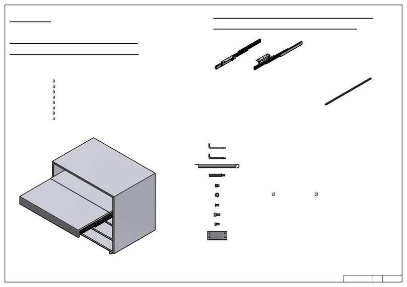
A - Distanziale per spalla - Side spacer (x 12)A - Distanziale per spalla - Side spacer (x 12)
Chiave esa. da 5 - n. 5 Allen keyChiave esa. da 5 - n. 5 Allen key
Chiave esa. da 4 - n. 4 Allen keyChiave esa. da 4 - n. 4 Allen key
B - Vite TCCE M6x12 - Socked head cap screw M6x12 (x 12)B - Vite TCCE M6x12 - Socked head cap screw M6x12 (x 12)
C - Vite TCCE M6x60 - Socked head cap screw M6x60 (x 4)C - Vite TCCE M6x60 - Socked head cap screw M6x60 (x 4)
D - Bussola in ottone mm 12x8 - 12x8 mm M6 Brass bush (x 12)D - Bussola in ottone mm 12x8 - 12x8 mm M6 Brass bush (x 12)
E - Riscontro per gancio piani - Striker for plane hook (x 2)E - Riscontro per gancio piani - Striker for plane hook (x 2)
F - Vite TPS truc. 3,5x16 - Tapered wood screw 3,5x16 (x 4)F - Vite TPS truc. 3,5x16 - Tapered wood screw 3,5x16 (x 4)
Chiave esa. da 3 - n. 3 Allen keyChiave esa. da 3 - n. 3 Allen key
G - Vite TPS M6x16 - Socked head tapered cap screw M6x16 (x4)G - Vite TPS M6x16 - Socked head tapered cap screw M6x16 (x4)
H - Vite TCCE M5x6 - Socked head cao screw M5x6 (x2)H - Vite TCCE M5x6 - Socked head cao screw M5x6 (x2)
I - Vite TCBCE M5x10 ISO 7380 - M5x10 ISO 7380 screw (x8)I - Vite TCBCE M5x10 ISO 7380 - M5x10 ISO 7380 screw (x8)
ISTRUZIONI DI MONTAGGIO
ASSEMBLY INSTRUCTIONS
MODELLI
MODELS:
411/78.1500.22 Party per modulo mm 600, spalle 16-19 mm
Party for 600 mm module, sides.16-19 mm
411/78.1510.22 Party per modulo mm 900 spalle 16-19
Party for 900 mm module, sides.16-19 mm
411/78.1520.22 Party per modulo mm 1200 spalle 16-19
Party for 1200 mm module, sides.16-19 mm
CONTENUTO DELLA CONFEZIONE
INCLUDED IN THE PACKAGING
SACCHETTO ACCESSORI
ACCESSORIES
1/10
rev 03
GUIDA SINISTRA
LEFT SLIDE GUIDA DESTRA
RIGHT SLIDE
TRAVERSO
CONNECTING BAR
PIATTO INFERIORE
LOWER PLATE
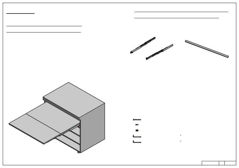
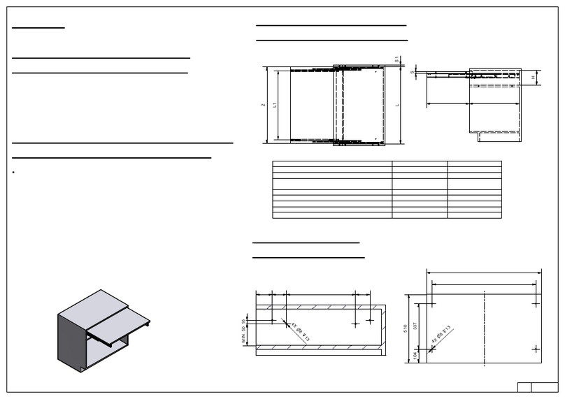
CODICE CODE MODULO M ODULE (L1) MIN/MAX L2 L3 L4 L5
411/78.1500.22 600 562/568 354,6 480 420 398
411/78.1510.22 900 862/868 654,6 780 720 698
411/78.1520.22 1200 1162/1168 954,6 1080 1020 998
Hmin Hmax
POS. 1 795 820
POS. 2 765 790
POS. 3 725 750
DIMENSIONI DI MASSIMA
GENERAL DIMENSIONS
2/10
INGOMBROINALTEZZA:65
OVERALLHEIGTH
ALTEZZADATERRA(H):
HEIGTHFORMGORUND
POS. 1
POS. 2
POS. 3
1824MASSIMA ESTENSIONE APERTO:
MAXIMUM LENGTH OPENED
L2
LARGHEZZA (L1)
WIDTH
MAX. LUNGHEZZA DA CHIUSO: 550
MAX OVERALL LENGTH CLOSED
L5
INTERASSEFORFISSAGGIOPIANO:L3
DISTANCEBETWEENPLANEFIXINGHOLES
L4
A-A
DIMENSIONE - DIMENSION SIMBOLO - SYMBOL
LUCE VERTICALE - VERTICAL FREE SPACE H MIN: 65 + S x 3
SPESSORE PIANI - PLANES THICKNESS S
PROFONDITA' INTERNA - INTERNAL FREE SPACE P MIN: 560
LARGHEZZA PIANI - PLANES WIDTH Z L - S x 2 - 3
LARGHEZZA MODULO - CABINET WIDTH L
A A
PIANO FISSO
FIXED PLANE
PRIMO PIANO RIBALTABILE
FIRST TILTING PLANE
SECONDO PIANO RIBALTABILE
SECOND TILTING PLANE
DIMENSIONI GENERALI MOBILE
GENERAL CABINET DIMENSIONS
3/10
Z
P
H
1379
725-820
445 445 529
R445
POSIZIONE FORI FISSAGGIO MECANISMO
HOLES FOR MECHANISM POSITION
36 64
455( ) 64
X16
355
n
10x4
50
LA QUOTA INDICATA DI 50 mm, LASCIA UNO SPAZIO
TRA LATO INFERIORE GUIDE E PIANETTO SOTTOSTANTE DI CIRCA 20 mm
THE INDICATED 50 mm DIMENSION IS TO ALLOW
A FREE SPACE BETWEN THE BOTTOM OF THE SLIDES
AND THE PLANE OF 20 mm
83
POSIZIONE LATO SUPERIORE GUIDE
TOP OF THE SLIDES
X+33
4/10
n
8 x 13
A
AA
A
B
B
B
B
529
241,577,5
Z
DIMENSIONI PIANETTI
PLANES DIMENSIONS
VISTA DAL BASSO
BOTTOM VIEW
PIANO FISSO
FIXED PLANE
PIANO FISSO
FIXED PLANE
PRIMO PIANO RIBALTABILE
FIRST TILTING PLANE
PRIMO PIANO RIBALTABILE
FIRST TILTING PLANE
SECONDO PIANO RIBALTABILE
SECOND TILTING PLANE
SECONDO PIANO RIBALTABILE
SECOND TILTING PLANE
L4(VEDIPAG.2)
(SEEPAG.2)
109
445
445
=
=
Z
Z
n
8 x 13
5/10
L3(VEDIPAG.2)
(SEEPAG.2)
n
12PROF.10
DEPTH:
D - Bussola in ottone 12x8 M6 ( x 16)D - Bussola in ottone 12x8 M6 ( x 16)
DET. ADET. A
DET. A
PREPARAZIONE DEL MOBILE
CABINET PREPARATION
12x8 M6 Brass bush L - Vite TCBCE M5x10 ISO 7380 (x 8)
M5x10 ISO 7380 screw
A - Distanziale per spalla (x12)
Side spacer
Inserire le bussole M6 nei fori praticati sulle spalle del mobile
Insert the M6 Bushes in cabinet walls holes
Per spalle del mobile inferiori a 19 mm bisogna fissare sulle
guide esterne i distanziali per spalla (A) forniti a corredo. Utilizzare
4 piastrini (1 x ogni posizione) per spalle da 18, 8 (2 x ogni posizione) per
spalle da 17 e 12 (3 x ogni posizione) per spalle da 16.
For cabinet sides smaller than 19 mm it is necessary to fix on the
external slides the include side spacers.
For 18 mm sides fix 4 spacers (1 x each position). For 17 mm sides
use 8 spacers (2 x each position). For 16 mm sides use 12 spacers
(3 x each position)
RIPETERE L'OPERAZIONE SULL'ALTRO LATO DEL MOBILE
REPEAT OPERATION ON THE OTHER CABINET SIDE
Chiave esagonale da 4
n°4 Socked wrench
6/10
Smontare la guida esterna svitando la vite indicata.
Disassembly the external slides unscrewing the indicated
screw
1
1
2
2
3
3
D
L
A
AA
A
MONTAGGIO DEL MECCANISMO SUL MOBILE
MOUNTING OF THE MECHANISM ON THE CABINET
B- Vite TCCE M6x12 (x 8)
Socked head cap screw M6x12
Chiave esagonale da 5
n°5 Socked wrench
Posizionare le guide esterne sul fianco del mobile, e fissarle
utilizzando 4 viti TCCE M6x12 per ciascun lato. Serrare con forza
utilizzando la chiave da 5 a corredo.
Iserire quindi il meccanismo sulle guide esterne e riavvitare
la vite precedentemente svitata.
Dopo aver chiuso il meccanismo, avvitare sotto ciascuna guida
esterna la vite "H" usando la chiave a brugola da 4.
Mount the external slides on the cabinet sides using 4 "B"
screws
M6x12 on each side. Thighten the screws using the n. 5 Allen
key.
Insert the mechanism on the external slides and screw the two
screws dismounted before.
After closing the mechanism, screw under the front of the
external
slides the two "H" M5x6 screw using the n. 4 Allen key.
7/10
H - Vite TCCE M5x6 (x 2)
Socked head cap screw M5x6
Chiave esagonale da 4
n°4 Socked wrench
B
H
AA
A
Y
8/10
MONTAGGIO DEI PIATTONI
PLATES ASSEMBLY
G
PIATTO INFERIORE
LOWER PLATE
G - Vite TPS M6x16 (x 4)
Socked head tapered cap screw M6x16
Chiave esagonale da 4
n°4 Socked wrench
B- Vite TCCE M6x12 (x 4)
Socked head cap screw M6x12
Chiave esagonale da 5
n°5 Socked wrench
B
TRAVERSO
CONNECTING BAR
AA
A
D - Bussola in ottone m 12x8 (x 4)
12x8 M6 Brass bush
PREPARAZIONE E FISSAGGIO DEI PIANI
PLANES ASSEMBLY
PIANO FISSO
FIXED PLANE
E - Riscontro per gancio piani (x 2)
Striker fo plane hook
F - Vite TPS truc. 3,5 x 14 (x 4)
Tapered wood screw 3,5x14
SECONDO PIANO RIBALTABILE
SECOND TILTING PLANE
Chiave esagonale da 5
n°5 Allen key
C - Vite TCCE M6x60 (x 4)
Socked head cap screw M6x60
9/10
C
"E"
"F"
"D"
AA
A
MONTAGGIO E REGOLAZIONE
ALTEZZA GAMBE
LEGS ASSEMBLY AND HEIGTH
REGULATION
10/10
Chiave esagonale da 4
n°4 Socked wrench
Chiave esagonale da 3
n°3 Allen key
POS. 1
POS. 2
POS. 3
REG x POS. 3
REG x POS. 2
REG x POS. 1
Usare chiave da 3 per avvitare
e svitare questi due grani (1 per
lato) e fissare la parte inferiore
della gamba in una delle tre
posizioni disponibili.
Use the n. 3 allen key to screw and
unscrew this grain and positioning
the lower part of the leg in one
of the three allowable positions
Inserire in questi fori la chiave da 4 per ruotare
grano che permette regolazione della altezza
della gamba di circa 25 mm
Insert in these holes the n. 4 allen key to allow
leg heigth regulation of about 25 mm
SEQUENZA DI FUNZIONAMENTO
FUNCTIONING SEQUENCE
CHIUSO
CLOSED
APERTURA DELLE GUIDE
SLIDES OPENING
SBLOCCO E ROTAZIONE DELLA GAMBA
LEG RELEASE AND ROTATION
ESTENSIONE E BLOCCO DELLA GAMBA
LEG EXTENTION AND LOCK
APERTURA DEI PIANI
PLANES OPENING APERTO
OPENED
PER CHIUDERE IL MECCANISMO
SPINGERE LE DUE LEVE ROSSE
IN PLASTICA VERSO L'INTERNO
TO CLOSE THE MECHANISM PUSH
TOWARD THE INSIDE THE TWO
RED PLASTIC PARTS
PER RUOTARE LA GAMBA, RUOTARE
LE DUE LEVE NERE POSTE SULLA
GUIDA INTERNA
TO ROTATE THE LEG, TURN THE TWO
BLACK LEVERS SITUATED ON THE
INTERNAL SLIDE
PER FAR RIENTRARE LA PARTE INFERIORE
DELLA GAMBA, SCHIACCIARE IL PULSANTE
GRIGIO
TO RETRACT THE LOWER PART OF THE LEG,
PUSH THE GREY BUTTON

This manual suits for next models

2

Other ATIM Indoor Furnishing manuals

ATIM 411/78.1105.22E User manual

ATIM

ATIM 411/78.1105.22E User manual

ATIM PRUA 411/78.1180.22 User manual

ATIM

ATIM PRUA 411/78.1180.22 User manual

ATIM Evolution XL 411/78.1621.25 User manual

ATIM

ATIM Evolution XL 411/78.1621.25 User manual

ATIM SHOT 411/78.1130.25 User manual

ATIM

ATIM SHOT 411/78.1130.25 User manual

ATIM SANDWICH 600 User manual

ATIM

ATIM SANDWICH 600 User manual

ATIM VULCANO TABLE 411/78 0504 User manual

ATIM

ATIM VULCANO TABLE 411/78 0504 User manual

ATIM OPLA Series User manual

ATIM

ATIM OPLA Series User manual

ATIM T-ABLE+39 411/39.1920.25X User manual

ATIM

ATIM T-ABLE+39 411/39.1920.25X User manual

ATIM LUNCH 450 User manual

ATIM

ATIM LUNCH 450 User manual

ATIM VOILA 411/78.1330.25 User manual

ATIM

ATIM VOILA 411/78.1330.25 User manual

Popular Indoor Furnishing manuals by other brands

Southern Enterprises Brandilyn CK843300TX Assembly instructions

Southern Enterprises

Southern Enterprises Brandilyn CK843300TX Assembly instructions

ZEITRAUM GUEST Assembly instructions

ZEITRAUM

ZEITRAUM GUEST Assembly instructions

LS BAILEY Assembly instructions

LS

LS BAILEY Assembly instructions

Lee & Plumpton SmartTop Series Assembly instructions

Lee & Plumpton

Lee & Plumpton SmartTop Series Assembly instructions

meubar TOMBA V6 Assembly instruction

meubar

meubar TOMBA V6 Assembly instruction

Sareer Rochelles Bed Assembly instructions

Sareer

Sareer Rochelles Bed Assembly instructions

Next 865122 Assembly instructions

Next

Next 865122 Assembly instructions

fantastic furniture Havana Queen MK2 manual

fantastic furniture

fantastic furniture Havana Queen MK2 manual

Furniture of America Enrico CM7068CK Assembly instructions

Furniture of America

Furniture of America Enrico CM7068CK Assembly instructions

Sensio Aspect installation instructions

Sensio

Sensio Aspect installation instructions

Costway JV10917 manual

Costway

Costway JV10917 manual

emob TOULON 07 Assembly instructions

emob

emob TOULON 07 Assembly instructions

Lorell LLR68565 quick start guide

Lorell

Lorell LLR68565 quick start guide

Furniture of America Golva CM7295Q Assembly instructions

Furniture of America

Furniture of America Golva CM7295Q Assembly instructions

Next 846713 Assembly instructions

Next

Next 846713 Assembly instructions

Coaster DONNY OSMOND home 130513 Assembly instruction

Coaster

Coaster DONNY OSMOND home 130513 Assembly instruction

Dorel Asia Baby Relax DA6564-1 Instruction booklet

Dorel Asia

Dorel Asia Baby Relax DA6564-1 Instruction booklet

CASUALPLAY Play Dire instructions

CASUALPLAY

CASUALPLAY Play Dire instructions

manuals.online logo
manuals.online logoBrands
  • About & Mission
  • Contact us
  • Privacy Policy
  • Terms and Conditions

Copyright 2025 Manuals.Online. All Rights Reserved.