Atlantic PRIMOCOSY HR BP User manual

FITTING INSTRUCTIONS
PRIMOCOSY HR BP / HR SRI BP
412236 - 412237
Family 4
N° 4126
Issue #
Date 02/2017

2
1. WARNINGS........................................................ 3
2. DESCRIPTION..................................................... 3
2.1 General points .............................................. 3
2.2 Construction................................................. 3
2.3 Composition................................................. 3
2.4 Technical specifications ................................. 4
2.5 Dimensions ................................................... 4
3. INSTALLATION .................................................. 5
3.1 Fitting connection points .............................. 5
3.2 Installation of casing ..................................... 5
3.3 Connection of air-flow
& associated terminals.................................. 6
4. ELECTRIC CABLING............................................ 7
5. EXTRACTION FLOW-RATE ADJUSTMENT ......... 8
5.1 Extraction flow-rate adjustment .................... 8
5.2 Washroom flow rate settings ........................ 8
6. BY-PASS PRINCIPLE ............................................ 9
7. ACCESSORIES (NOT SUPPLIED)......................... 9
8. ANNUAL MAINTENANCE ................................ 10
8.1 Filter clogging indicator .............................. 10
8.2 Changing filters........................................... 10
8.3 Maintenance of exchanger and
motorised fans............................................ 11
9. WARRANTY ..................................................... 12
10. PROTECTING THE ENVIRONMENT................ 12
CONTENTS

3
1. WARNINGS
READ INSTRUCTIONS BELOW CAREFULLY BEFORE INSTALLATION:
If the advice and warnings in these instructions are ignored, the manufacturer cannot assume liability for any injury or damage suffered
by people or property.
The instructions describe how to install, use and maintain the appliance correctly. Respecting these instructions ensures effective and
sustainable use of the appliance.
Do not use this appliance for any purpose other than that for which it is intended.
After unpacking, check it is in good condition. If there are any problems, contact your dealer for help.
Use of any electrical appliance implies respect for the following basic rules:
- do not touch the appliance with moist or wet parts of the body (hands, feet, etc.).
- this appliance is not designed for use by people (including children) of reduced physical, sensory or mental capacity, or those inexperienced
or ignorant, unless they have received prior instruction or supervision in the use of the appliance from someone responsible for their safety.
Children must be supervised to ensure they do not play with the appliance.
- The appliance is designed to be installed inside a building. Do not connect the appliance to the main electricity supply unless it complies
with the specifications shown on the information plate.
- before working on the appliance, turn off the electricity supply and make sure it cannot be restored accidentally.
- Provide a 2A circuit-breaker for protection upstream.
This equipment must be installed by suitably qualified persons.
The installation must comply with NF C 15-100 and with professional standards. Each product or component of the installation must also
comply with the relevant standards.
2. DESCRIPTION
2.1 General points
Dual flow control unit for private house, from T2 to T7, with a maximum of 4 washrooms. Horizontal installation in roofspace, ideal for
renovation and replacement of existing products.
Primocosy HR / HR SRI: High-performance heat exchanger.
BY-PASS function for the exchange to bring cool air in during summer nights.
Individual room airflow controls with regulators in the connection points. Automatic, built-in de-icing system. Hi-flow kitchen intake with
remote controls (SRI model) or switch.
2.2 Construction
Insulated casing in PPE and sheet steel cover with foam insulation. G4 filters on intake and extraction, fitted on metal frames.
Primocosy HR: High-performance, contraflow exchange, low-energy EC 2-speed motors.
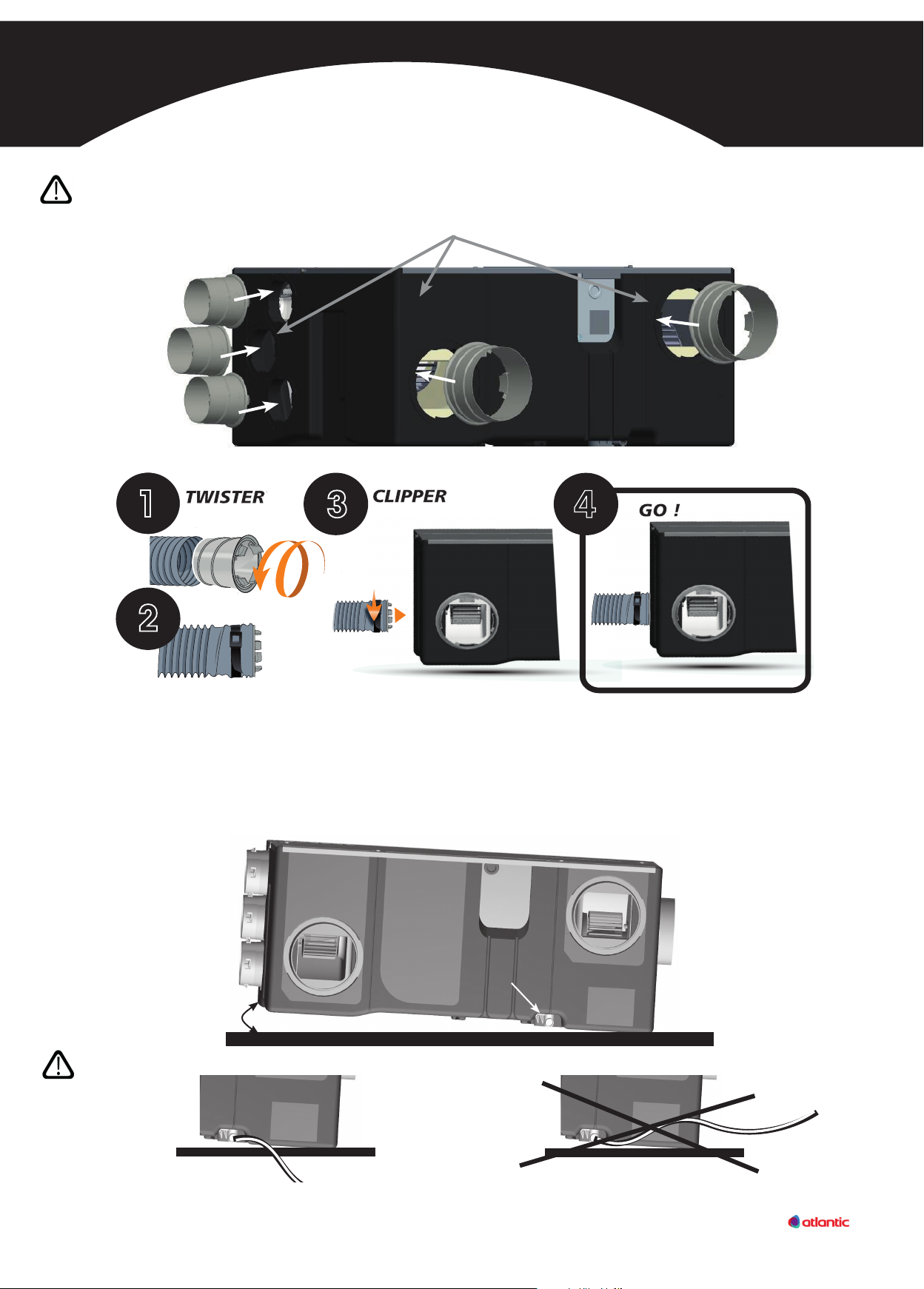
2.3 Composition
• 4 washroom connection points, Ø80 regulated at 15 or 30 m3/h.
• 2 Ø80 plugs.
• 1 kitchen connection point Ø125 regulated.
• 1 used air discharge connection point Ø125.
• 1 fresh air intake connection Ø125.
• 1 forced intake connection point Ø125.
• 8 clamping sleeves.
• 1 siphon fitted to the product for condensate collection.
• 1 switch for hi-flow kitchen connection, BY-PASS or
1 radio remote control for SRI versions.
• 1 filter clogging indicator panel.
4 washroom connection
points, Ø80 regulated at
15 or 30 m3/h
1 used air discharge connection point Ø125
1 forced intake connection
point Ø125
1 kitchen connection point Ø125
regulated
1 connection point
for fresh air Ø125
2 Ø80 plugs
SRI version
1 radio remote control
1 clamping collar for
connecting condensate
discharge
1 switch for
kitchen hi-flow
Standard version
Composition for all models
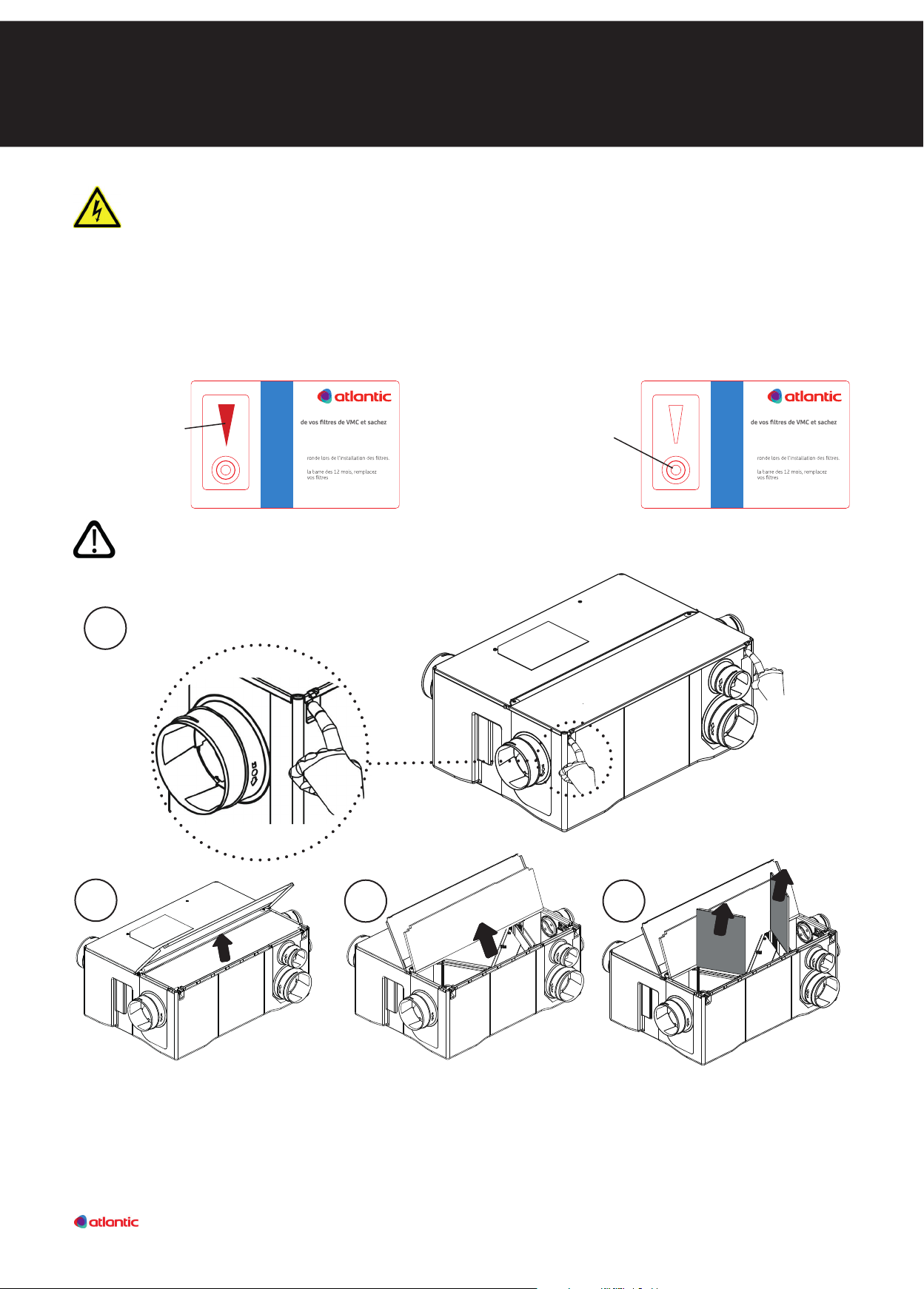
MODE D’EMPLOI
1/ Appuyer pour enclencher la pastille
2/ Lorsque le témoin rougeatteint
(réf.: 412190)
INDI
CATEUR DE CHANGEMENT
DE FI
L
TRES VMC
www.boutique-atlantic.fr
Avec cette carte, suivez l’usure
quand leschanger.
Filtres disponibles sur la boutique Atlantic :
1 filter clogging
indicator panel

4
2.4 - Technical specications
Power supply: single-phase ~ 230 V – 50 Hz
* For standard 22 hr low-speed versions and 2hr high-speed versions For SRI 23 hr low-speed versions and 1hr high-speed versions
2.5 Dimensions
Current Power
consumption Weighted
power*
PV GV PV GV
PRIMOCOSY HR 0.4A 0.6A 40W 122W 47.1 W.th.C
PRIMOCOSY HR SRI 0.4A 0.6A 40W 122W 43.7 W.th.C
490
700
300
Ø125 Ø125 3 X Ø80
Ø125 Ø80
70 700 70
Ø125
Fixed plate
70 490 70

5
3. INSTALLATION
3.2. Casing installation
Attach the condensate discharge connector (on the product) to the waste water system (Ø16 int. pipe not supplied) using the clamping
sleeve. The appliance must be fitted with a 3cm or 5% gradient so that the condensates flow off naturally. The condensate discharge
pipe and the connector must be insulated to prevent freezing.
Check the connector is properly fitted under the product after installation.
Check the sealing of the whole assembly, and the run-off of the condensates.
WARNING: Check the discharge pipe never rises above the level of the condensates connector.
For easier maintenance, leave a 300mm space above and behind the appliance.
3 cm or 5%
Condensates connection
OK NOK
Note: Condensates connection has a built-in siphon. There is no need to install another
siphon on the outlet.
Do not dismantle moving parts to install connection points.
SEAL THE FITTING IN THE PIPE
USING THE CLAMPING SLEEVE
4
in reverse
+ 1/4 OF A TURN
3.1. Fitting connection points

6
3.3. Air-ow connection & associated terminals
Used air outlet
(not supplied)
Fresh air intake
(not supplied)
Adjustment register
RR125 (not supplied)
Distribution
casing
NEOCD 80S
(not supplied)
Kitchen
Ø125
Blower
Ø80
Washrooms
Ø80
Kitchen
connection with
regulator X 1
X 3
Fresh air inlet
Used air outlet Fresh air blowing
Washroom extraction
Kitchen extraction
To prevent unwanted load losses, it is vital:
• to avoid unnecessary elbow joints,
• to extend straight sections without pulling,
• not to crush the conduits,
• to limit the length of the conduits,
• to plug unwanted outlets with the plugs supplied.
Example of system with distribution casing:

7
DISCONNECT THE POWER SUPPLIED BEFORE CARRYING OUT ANY WORK AND MAKE SURE
THE POWER CANNOT BE TURNED ON AGAIN BY ACCIDENT.
PRIMOCOSY HR BP WIRING
For SRI models: pressing the remote control button switches to high speed (after configuring the remote control, see the manual). The
appliance then operates at high speed for about 30 minutes.
If the SRI remote control is no longer communicating
with the PRIMOCOSY, remove the protective cover on
the front of the electric boiler with a flat screwdriver.
Once the cover is off, insert the tip of a paper clip
into the hole to do a reset.
See the SRI remote control manual for the
parameters.
PRIMOCOSY HR SRI BP
BROWN
PHASE
EARTH
NEUTRAL
CASING CABLE
FACTORY WIRINGINSTALLER WIRING
BLUE OR GREY
230V POWER SUPPLY
4. ELECTRIC CABLING
RESET access
This equipment must be installed by suitably qualied persons.
The installation must comply with NF C 15-100 and with professional standards. Each product or component of the
installation must also comply with the relevant standards.
Provide a 2A circuit-breaker for protection (not supplied).
1 metre cable supplied. Connect using a sealed junction box (not supplied).
The appliance motors have electronic protection.
I
0
PHASE
BY-PASS
PV / GV
I
0
GREY
BLACK CASING CABLE
BROWN
EARTH
EARTH
PHASE
BLUE
NEUTRAL

8
5. EXTRACTION FLOW-RATE ADJUSTMENT
This unit is suitable for up to 4 sanitation facilities (each room with a water outlet, except for the kitchen), with 3 bathrooms (or showers)
at most.
* A washroom is a room with one water outlet, but without bath or shower (cellar, laundry room, toilet with washbasin, etc.).
5.2. Washroom ow rate settings
REGULATORY AIRFLOWS EXPRESSED IN m³/h
Number of principal
rooms in the dwelling Kitchen Bathroom or shower room,
including a toilet cubicle
Another
washroom*
Toilet cubicle
Single Multiple
2
3
4
5 and more
90
105
120
135
15
30
30
30
15
15
30
30
15
15
30
30
15
15
15
15
Check the terphane ap is in the correct position in the WC connection.
Identification of connection
"SDB" (30 m³/h)
Identification of connection
"WC" (15 m³/h)
Correct position
(Section view)
Wrong position
(Section view)
If the flap is in the wrong position, put it in
the correct one (Section view)
Replace the
flap in its
housing up to
the "clip"
Flap for
regulation
Flap for
regulation
5.1. Extraction ow-rate adjustment
Regulatory air flows:
Balancing flow rates:
If a significant divergence is found between the flow rate in and the flow rate out, balance it using a manual register RR125 (see p. 9).

9
This is for balancing flow rates
It compensates for any imbalance.
To be installed on the forced intake system.
• RR 125 (code 523 451): manual control adjustment register
Consider insulating the register with mineral wool.
• 4 PB 80 NP: WC / bathroom extraction outlet
(Ø 80 / L = 100 mm)
• 1 GB 125 NP: kitchen extraction outlet
(Ø125 / L = 100 mm)
• Clamping sleeves
• 6 ONDEA 80 P: intake (Ø 80 / L = 275
mm).
• 1 NEOCD 80 S
distribution casing.
• ME S/STEEL 125 (code: 464 040):
air intake.
• CPR 125 R (code: 422 563):
Roof outlet.
• T 82 ALU CR 50 (code: 423 025):
Flexible, insulated ducts (Ø 80 mm).
• T 127 ALU CR 50 (code: 423 026):
Flexible, insulated ducts (Ø 125 mm).
• KIT SUSP PRIMO code 412212 Suspension kit for Primocosy.
• T CONDENSATE 10 M code 412209 Condensate connection tube Ø 16 mm, L = 10 m.
This function by-passes the exchanger to reduce heating in dwellings on summer nights. Limit cooling of the dwelling on spring or autumn
days (for SRI versions the function is triggered for 12 hours, and can be stopped by pressing the button again).
The BY-PASS is activated by putting the switch in position 1, or pressing the button for SRI versions.
Principe :
Equilibrage réseau d’insuation :
Une fois le réseau installé, il est né cessaire de régler les bouches d’insu ation (air neuf), le débit doit être
équiréparti dans toutes les pièces. Pour cela ouvrir toutes les bouches du réseau. Commencer par la bouche
la plus éloignée de la centrale, véri er qu’il y a un débit minimum. Ensuite passer à la suivante, la fermer de
quelques tours puis répéter l’ opération sur toutes les bouches d’insuat ion en les fermant de plus en plus
au fur et à mesure que l’on se rapproche de la centrale.
Warm
Warm
Warm
Warm
Cold
Cool
Cool
Cool
Exchange
Exchange
By-pass
By-pass
SUMMER Day
SUMMER Night
WINTER
SPRING
AUTUMN
3
4
20°C
18°C 20°C
8°C
Principe :
Equilibrage réseau d’insuation :
Une fois le réseau installé, il est né cessaire de régler les bouches d’insu ation (air neuf), le débit doit être
équiréparti dans toutes les pièces. Pour cela ouvrir toutes les bouches du réseau. Commencer par la bouche
la plus éloignée de la centrale, véri er qu’il y a un débit minimum. Ensuite passer à la suivante, la fermer de
quelques tours puis répéter l’ opération sur toutes les bouches d’insuat ion en les fermant de plus en plus
au fur et à mesure que l’on se rapproche de la centrale.
Warm
Warm
Warm
Warm
Cold
Cool
Cool
Cool
Exchange
Exchange
By-pass
By-pass
SUMMER Day
SUMMER Night
WINTER
SPRING
AUTUMN
1
2
26°C
20°C
25°C 18°C
Other accessories:
7. ACCESSORIES (NOT SUPPLIED)
Accessories kit for PRIMOCOSY 412239 contains:
6. BY-PASS PRINCIPLE

10
8. ANNUAL MAINTENANCE
• Remove the exchanger to dust it
NEVER USE ANY LIQUID, WHETHER WATER OR DETERGENT
• Change filters
• Dust motorised fans with a dry brush
• Check and clean siphon
• Clean openings
• Check that the BY-PASS is clean
DISCONNECT THE POWER SUPPLIED BEFORE CARRYING OUT ANY WORK AND MAKE SURE
THE POWER CANNOT BE TURNED ON AGAIN BY ACCIDENT.
MODE D’EMPLOI
1/ Appuyer pour enclencher la pastille
2/ Lorsque le témoin rouge atteint
(réf. : 412190)
INDI
CATEUR DE CHANGEMENT
DE FI
LTRES VMC
www.boutique-atlantic.fr
Avec cette carte, suivez l’usure
quand leschanger.
Filtres disponibles sur la boutique Atlantic :
MODE D’EMPLOI
1/ Appuyer pour enclencher la pastille
2/ Lorsque le témoin rouge atteint
(réf. : 412190)
INDI
CATEUR DE CHANGEMENT
DE FI
LTRES VMC
www.boutique-atlantic.fr
Avec cette carte, suivez l’usure
quand leschanger.
Filtres disponibles sur la boutique Atlantic :
When the indicator
is full, change the
filters.
A new indicator is supplied with
replacement filters. Press the button to
start the 12-month period.
To ensure the indicator starts up
properly, check that a red border
appears.
Ensure the indicator is reliable by keeping it a temperate location, between 20°C and 24°C.
8.1. Filter clogging indicator
8.2. Change lters
3
2
Press the two hooks closing the top
panel to access the filters.
1
4

11
8.3. Maintenance of exchanger and motorised fans
Unscrew the 4 crosshead screws to access the exchanger and
the motorised fans.
2
1
When refitting, reconnect the BY-PASS checking that the earth connection is properly attached. Make sure the cover
is replaced the right way round, taking care the closure hooks are properly in place. Screw up the 4 crosshead screws.
Pull out the motorised fan
units to dust them with a
dry brush.
Motorised fan unit
Disconnect the terminal strip before
removing the BY-PASS / exchanger assembly.
Grasp at the sides and pull out upwards.
Carefully clean the exchanger using a
domestic vacuum cleaner.
DO NOT USE LIQUID OF ANY KIND,
WHETHER WATER OR DETERGENT.
3
BY-PASS
DO NOT PRESS ON
THE BY-PASS

© - Non-contractual photos - 0510 - Atlantic Climatisation et Ventilation - 13, bd Monge - 69330 Meyzieu - A simplified joint-stock company with €2,916,400 - RCS Lyon B 421 370 289
Installer's stamp:
Recycling electrical or electronic equipment at the end of its life (applicable in European Union countries and other countries
with selective collection systems). This logo means the product must not be processed with household waste. It must be
taken to a suitable collection point for recycling electrical and electronic equipment. For any further information about
recycling this product, you can contact your town hall, waste disposal site or the store where you purchased the product.
9. WARRANTY
This appliance is guaranteed against all manufacturing faults for two years from the date of purchase. For this, ATLANTIC Climatisation
et Ventilation offers exchange or supply of parts found to be defective after inspection by its after-sales service. In no case may the
warranty cover additional costs, such as labour, transport or compensation of any kind. The warranty does not cover damage caused
by installation that does not comply with these instructions, improper use or attempted repair by unqualified personnel. In the event of
any problem, please contact your installer, or else your retailer.
10. PROTECTING THE ENVIRONMENT
Registered office:
Atlantic Climatisation et Ventilation
13, Bd Monge - ZI - BP 71 - 69882 Meyzieu Cedex
T: +33 4 72 45 19 45
www.atlantic-comfort.com
Local dealer Australia & New Zealand
Suite 4 | 13-25 Church Street
Hawthorn | Victoria AUSTRALIA | 3122
T: +61 (03) 9852 9599
www.atlantics.com.au
This manual suits for next models
3
Table of contents