manuals.online logo
Brands
  1. Home
  2. •
  3. Brands
  4. •
  5. Atlas Copco
  6. •
  7. Air Compressor
  8. •
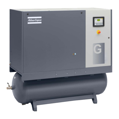
  9. Atlas Copco GA 37 VSD User manual

Atlas Copco GA 37 VSD User manual

Other manuals for GA 37 VSD

1

This manual suits for next models

1

Other Atlas Copco Air Compressor manuals

Atlas Copco ZT-55 User manual

Atlas Copco

Atlas Copco ZT-55 User manual

Atlas Copco ZR-55 User manual

Atlas Copco

Atlas Copco ZR-55 User manual

Atlas Copco GA 75 VSD User manual

Atlas Copco

Atlas Copco GA 75 VSD User manual

Atlas Copco G 160 VSD User manual

Atlas Copco

Atlas Copco G 160 VSD User manual

Atlas Copco XAMS 1150 CD7 T3 APP User manual

Atlas Copco

Atlas Copco XAMS 1150 CD7 T3 APP User manual

Atlas Copco GA 5 VSD MED User manual

Atlas Copco

Atlas Copco GA 5 VSD MED User manual

Atlas Copco PNS 1250 Cud S3A/T3 APP User manual

Atlas Copco

Atlas Copco PNS 1250 Cud S3A/T3 APP User manual

Atlas Copco XAS 185 CD7 T4F HOP User manual

Atlas Copco

Atlas Copco XAS 185 CD7 T4F HOP User manual

Atlas Copco C9C Compact User manual

Atlas Copco

Atlas Copco C9C Compact User manual

Atlas Copco GA 37+ User manual

Atlas Copco

Atlas Copco GA 37+ User manual

Atlas Copco PTS 916 Cd User manual

Atlas Copco

Atlas Copco PTS 916 Cd User manual

Atlas Copco GA 30+ User manual

Atlas Copco

Atlas Copco GA 30+ User manual

Atlas Copco GA55 User manual

Atlas Copco

Atlas Copco GA55 User manual

Atlas Copco GA 30+ User manual

Atlas Copco

Atlas Copco GA 30+ User manual

Atlas Copco LE2 User manual

Atlas Copco

Atlas Copco LE2 User manual

Atlas Copco ZT Series User manual

Atlas Copco

Atlas Copco ZT Series User manual

Atlas Copco G 18 User manual

Atlas Copco

Atlas Copco G 18 User manual

Atlas Copco GA5 User manual

Atlas Copco

Atlas Copco GA5 User manual

Atlas Copco GA15 User manual

Atlas Copco

Atlas Copco GA15 User manual

Atlas Copco XAHS 146 Dd S3B APP User manual

Atlas Copco

Atlas Copco XAHS 146 Dd S3B APP User manual

Atlas Copco GA 160 VSD User manual

Atlas Copco

Atlas Copco GA 160 VSD User manual

Atlas Copco AUTOMAN AC40 User manual

Atlas Copco

Atlas Copco AUTOMAN AC40 User manual

Atlas Copco LFx 0.7 User manual

Atlas Copco

Atlas Copco LFx 0.7 User manual

Atlas Copco SK 160 SA 1 User manual

Atlas Copco

Atlas Copco SK 160 SA 1 User manual

Popular Air Compressor manuals by other brands

Craftsman 919.724591 owner's manual

Craftsman

Craftsman 919.724591 owner's manual

Hitachi Highly WHP11500VSDPC9EQ installation manual

Hitachi

Hitachi Highly WHP11500VSDPC9EQ installation manual

Craftsman 919.167810 owner's manual

Craftsman

Craftsman 919.167810 owner's manual

Yamato 24/2 M1CD instruction manual

Yamato

Yamato 24/2 M1CD instruction manual

Clarke 2242117 Operation & maintenance instructions

Clarke

Clarke 2242117 Operation & maintenance instructions

Sparmax DC-25XR user manual

Sparmax

Sparmax DC-25XR user manual

Briggs & Stratton Air Compressor Operator's manual

Briggs & Stratton

Briggs & Stratton Air Compressor Operator's manual

Fini F3GST2TK Operator's manual

Fini

Fini F3GST2TK Operator's manual

Campbell Hausfeld RP3300 Easy setup guide

Campbell Hausfeld

Campbell Hausfeld RP3300 Easy setup guide

Ingersoll-Rand UP6 20 HP Option manual

Ingersoll-Rand

Ingersoll-Rand UP6 20 HP Option manual

Parkside PKO 270 A1 operating instructions

Parkside

Parkside PKO 270 A1 operating instructions

Clas Ohlson QIE-ZTH-15 manual

Clas Ohlson

Clas Ohlson QIE-ZTH-15 manual

Ferm CRM1046 Original instructions

Ferm

Ferm CRM1046 Original instructions

BE AC153 Operation manual

BE

BE AC153 Operation manual

RIDGID OF25150A Operator's manual

RIDGID

RIDGID OF25150A Operator's manual

Johnson Controls QUANTUM LX Setup

Johnson Controls

Johnson Controls QUANTUM LX Setup

Ring Automotive RAC700 instructions

Ring Automotive

Ring Automotive RAC700 instructions

Craftsman 919.184190 owner's manual

Craftsman

Craftsman 919.184190 owner's manual

manuals.online logo
manuals.online logoBrands
  • About & Mission
  • Contact us
  • Privacy Policy
  • Terms and Conditions

Copyright 2025 Manuals.Online. All Rights Reserved.


Oil-injected rotary screw compressors


Oil-injected rotary screw compressors
GA 37 VSD, GA 45 VSD
Any unauthorized use or copying of the contents or any part thereof is prohibited.
This applies in particular to trademarks, model denominations, part numbers and drawings.
This instruction book is valid for CE as well as non-CE labelled machines. It meets the
requirements for instructions specified by the applicable European directives as identified
in the Declaration of Conformity.
2015 - 01
            
www.atlascopco.com

Instruction book



1904 0504 83
ϯ



                                                    

1.1SAFETY ICONS ....................................................................................................................... 6
1.2SAFETY PRECAUTIONS, GENERAL ...................................................................................... 6
1.3SAFETY PRECAUTIONS DURING INSTALLATION................................................................ 7
1.4SAFETY PRECAUTIONS DURING OPERATION .................................................................... 9
1.5SAFETY PRECAUTIONS DURING MAINTENANCE OR REPAIR......................................... 10


                                              
 

2.1INTRODUCTION.................................................................................................................... 13
2.2AIR FLOW .............................................................................................................................. 17
2.3OIL SYSTEM.......................................................................................................................... 19
2.4COOLING SYSTEM ............................................................................................................... 20
2.5CONDENSATE SYSTEM ....................................................................................................... 22
2.6REGULATING SYSTEM......................................................................................................... 23
2.7ELECTRICAL SYSTEM.......................................................................................................... 23
2.8AIR DRYER............................................................................................................................ 24
2.9SMARTBOX AND SMARTLINK.............................................................................................. 25


          !     "                                                                                          
 #

3.1ELEKTRONIKON® GRAPHIC CONTROLLER ....................................................................... 28
3.2CONTROL PANEL ................................................................................................................. 30
3.3ICONS USED ......................................................................................................................... 31
3.4MAIN SCREEN....................................................................................................................... 35
3.5CALLING UP MENUS ............................................................................................................ 39
3.6INPUTS MENU....................................................................................................................... 40
3.7OUTPUTS MENU................................................................................................................... 43
3.8COUNTERS ........................................................................................................................... 45
$

    %     &   '       (                              
# 
Instruction
book


ϰ
1904 0504 83



4.1ENERGY RECOVERY UNIT .................................................................................................. 82
4.2ENERGY RECOVERY SYSTEMS.......................................................................................... 83
4.3OPERATION .......................................................................................................................... 84
4.4MAINTENANCE ..................................................................................................................... 88
4.5ENERGY RECOVERY DATA................................................................................................. 88
)

*                                            + ,

5.1DIMENSION DRAWINGS....................................................................................................... 90
5.2INSTALLATION PROPOSAL.................................................................................................. 92
5.3ELECTRICAL CONNECTIONS .............................................................................................. 95
5.4COOLING WATER REQUIREMENTS.................................................................................... 97
5.5PICTOGRAPHS ....................................................................................................................102


-      %                                          

,


6.1BEFORE INITIAL START-UP................................................................................................103
6.2BEFORE STARTING.............................................................................................................106
6.3STARTING ............................................................................................................................107
6.4DURING OPERATION ..........................................................................................................108
6.5CHECKING THE DISPLAY....................................................................................................110
6.6STOPPING............................................................................................................................111
6.7TAKING OUT OF OPERATION.............................................................................................112
.

/                                               


7.1PREVENTIVE MAINTENANCE SCHEDULE.........................................................................113
7.2OIL SPECIFICATIONS ..........................................................................................................116
7.4AIR FILTER ...........................................................................................................................117
7.5OIL AND OIL FILTER CHANGE ............................................................................................118
7.6COOLERS.............................................................................................................................120
7.7SAFETY VALVES..................................................................................................................121
7.8DRYER MAINTENANCE INSTRUCTIONS............................................................................121
7.9SERVICE KITS......................................................................................................................122
Instruction book



1904 0504 83
ϱ


7.10DRAINING CONDENSATE FROM THE OIL TANK...............................................................122
7.11STORAGE AFTER INSTALLATION ......................................................................................123
7.12DISPOSAL OF USED MATERIAL .........................................................................................123
#

0   1  2   &  %                                  
  $

+

3   "                                             
 
+

9.1READINGS ON DISPLAY .....................................................................................................129
9.2ELECTRIC CABLE SIZE AND MAIN FUSES ........................................................................129
9.3PROTECTION SETTINGS ....................................................................................................133
 


*                                              
 
+

Instruction
book


ϲ
1904 0504 83




4 5 6 7 8 9 8 : ; < 9
Danger for life
Warning
Important note
= > 9> ? 8 7 6 ?>@8 A : ; < 9 B
C D
To be read attentively and acted accordingly before installing, operating, repairing or
decommissioning the unit
E D
These recommendations apply to machinery processing or consuming air or insert gas.
F D
Processing of any other gas requires additional safety precautions typical to the application,
which are not included herein.
G D
In addition to normal safety rules, which should be observed with stationary air compressor and
equipment, the following safety directions and precautions are of special importance.
HD
Any modification on the compressor shall only be performed in agreement with Atlas copco and
under stricter of the two shall apply
I D
The operator must employ safe working practices and observe all related work safety
requirements and regulations.
JD
If any of the following statements does not comply with the applicable legislation, the stricter of
the two shall apply.
K D
Installation, operation, maintenance and repair work must only be performed by authorized,
trained, specialized personnel.
L D
The compressor is not considered capable of producing air of breathing quality. For air of
breathing quality, the compressed air must be adequately purified according to the applicable
legislation and standards.
C M D
Before any maintenance, repair work, adjustment or any other non-routine checks:
•Stop the compressor.
•Press the emergency stop button.
•Switch off the voltage.
•Depressurize the compressor.
•Lock Out – Tag Out (LOTO):
- Open the power isolating switch and lock it with a personal lock.
- Tag the power isolating switch with the name of the service technician.
•On units are powered by a frequency converter, wait 10 minutes before starting any
electrical repair.
•Never rely on indicator lamps or electrical door locks before maintenance work, always
disconnect and check with measuring device.
C C D
The units are powered by a frequency converter, wait 10 minutes before starting any electrical
repair.
Instruction book



1904 0504 83
ϳ

In a domestic environment, this product may cause radio interference in which
case supplementary mitigation measures are required.
If the machine is equipped with an automatic restart after voltage failure function
and if this function is active, be aware that the machine will restart automatically
when the power is restored if it was running when the power was interrupted
C E D
Never play with compressed air. Do not apply the air to your skin or direct an air stream at
people. Never use the air to clean dirt from your clothes. When using the air to clean equipment,
do so with extreme caution and wear eye protection.
C F D
The owner is responsible for maintaining the unit in safe operating condition. Parts and
accessories shall be replaced if unsuitable for safe operation.
C G D
It is not allowed to walk or stand on the roof of the compressor canopy.
All responsibility for any damage or injury resulting from neglecting these
precautions, or non observance of the normal caution and care required for
installation, operation, maintenance and repair, even if not expressly stated,
will be disclaimed by the manufacturer
.
N?>@8 A : ; < 9 B O A ?;9P <6> ? 8 : ; < 9
C D
Apart from general engineering practice in conformity with the local safety regulations, the
following directives are specially stressed:
E D
In proposals/quotes to the customer it should be mentioned mandatory to ask for lockable
isolators at customer installation, the same has to be added in AIB for commissioning/servicing
of the machine. Need of lockable isolators to be clearly communicated to customers.
F D
A compressor shall be lifted only with adequate equipment in conformity with local safety rules.
Please consult Atlas Copco to check if a dedicated lifting devise is designed for this purpose.
Loose or pivoting parts shall be securely fastened before lifting. It is strictly forbidden to dwell or
stay in the risk zone under a lifted load. Lifting acceleration and retardation shall be kept within
safe limits.
G D
The units is designed for indoor use . If the unit is installed outdoors, special precautions must
be taken; consult your supplier.
HD
In case the devise is a compressor, place the machine where the ambient air is as cool and
clean as possible if necessary, install a suction duct. Never obstruct the air inlet. Care must b
taken to minimize the entry of moisture at the inlet air
I D
Any blanking flanges, plugs, caps and desiccant bags must be removed before connecting the
pipes.
JD
Air hoses must be of correct size and suitable for the working pressure. Never use frayed,
damaged or worn hoses. Distribution pipes and connections must be of the correct size and
suitable for the working pressure.
K D
In case the devise is a compressor, the aspirated air must be free of flammable fumes, vapours
and particles, e.g. paint solvents, that can lead to internal fire or explosion.
L D
In case the dives is a compressor, arrange the air intake so that loose clothing worn by people
cannot be drawn in.
C M D
Ensure that the discharge pipe from the compressor to the aftercooler or air net is free to
expand under heat and that it is not in contact with or close to flammable materials.
C C D
No external force may be exerted on the air outlet valve; the connected pipe must be free of
strain.
C E D
If remote control is installed, the machine must bear a clear sign stating: DANGER: This
machine is remotely controlled and may start without warning.
The operator has to make sure that the machine is stopped and depressurized and that the
Instruction
book


ϴ
1904 0504 83


electrical isolating switch is open, locked and labeled with a temporary warning before any
maintenance or repair. As a further safeguard, persons switching on remotely controlled
machines shall take adequate precautions to ensure that there is no one checking or working on
the machine. To this end, a suitable notice shall be affixed to the start equipment.
C F D
Air-cooled machines must be installed in such a way that an adequate flow of cooling air is
available and that the exhausted air does not recirculate to the compressor air inlet or cooling
air inlet.
C G D
The electrical connections must correspond to the applicable codes. The machines must be
earthed and protected against short circuits by fuses in all phases. A lockable power isolating
switch must be installed near the compressor.
CHD
On machines with automatic start/stop system or if the automatic restart function after voltage
failure is activated, a sign stating "This machine may start without warning" must be affixed near
the instrument panel.
C I D
In multiple compressor systems, manual valves must be installed to isolate each compressor.
Non-return valves (check valves) must not be relied upon for isolating pressure systems.
CJD
Never remove or tamper with the safety devices, guards or insulation fitted on the machine.
Every pressure vessel or auxiliary installed outside the machine to contain air above
atmospheric pressure must be protected by a pressure relieving device or devices as required.
C K D
Piping or other parts with a temperature in excess of 70°C (158°F) and which may be
accidentally touched by personnel in normal operation must be guarded or insulated. Other high
temperature piping must be clearly marked.
C L D
For water-cooled machines, the cooling water system installed outside the machine has to be
protected by a safety device with set pressure according to the maximum cooling water inlet
pressure.
E M D
If the ground is not level or can be subject to variable inclination, consult the manufacturer.
E C D
If the device is a dryer and no free extinguishing system is present in the air close to the dryer,
safety valves must be installed of the dryer.
E E D
Never Drill holes in an electrical cabinet. Small metallic burrs can cause short-circuits in
electrical components
E F D
Make sure to avoid condensation on electrical components (e.g. cubicle, Elektronikon and
frequency converter)
E G D
To preserve the protection of the electric cabinet and to protect its components from dust from
the environment and the entry of moisture in the electrical cabinet. It is absolutely necessary to
use a proper cable gland when connecting the power supply cable to the compressor.
Q B >< R 8 9 ; S 6 ?< 6 > ? @ 8 T 7 >P 7 8 9 O @8 9 ? > B A 7 : ; 9 O 8 S 8 P >: < < ?R 8 ; 7 A ? > < R : U > > V A ; 6 S >9 : W X U ; B
@< A 7 O 8 7 B < ? > B A 7 : ; 9 R ; ? > 8 9 O R 8 : 8 7 ; : ; >B W
EHD
Avoid contact with sharp edges hot surfaces to prevent damage to cable insulation.
E I D
Before initial start-up and after service interventions, make sure the following final inspection
checks are made:
a. Inspect all electrical connections to verify there are no loose connections and all are
tightened correctly
b. Check for strain relief on the (main) power cables.
c. Verify that the power requirement for the unit has been provided for by referencing to the unit
power label on the inside of the electrical cabinet door of the unit
d. The branch circuit protection and supply cable size for the compressor must be sized to
meet the power requirement per local electrical codes
e. Verify that the unit is correctly grounded using the proper size of wire connected to a tested
earth ground
Y 9 Z S 6 ?<6>? >7> @ :?;@8 7 ; 9 B : 8 7 7 8 : ; < 9 @8 9 ? > B A 7 : ; 9 O 8 S 8 P >: < < ?R 8 ; 7 A ? > < R : U > > V A ; 6 S >9 : W
X U ; B @< A 7 O 8 7 B < ? > B A 7 : ; 9 R ; ? > 8 9 O R 8 : 8 7 ; : ; >B W
EJD
Before initial start-up and after service inventions , make sure the following final mechanical
inspection check are made:
a. Inspect all connections to make sure they are tight, sealed and secured.
b. Visually inspect metal or nylon tubing located in the compressor. Tubes can come loose or
get damaged in shipping. Verify the flexibility of the nylon tubes while inspecting for damage.