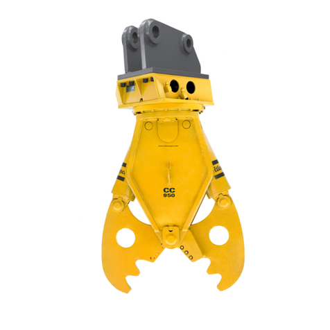
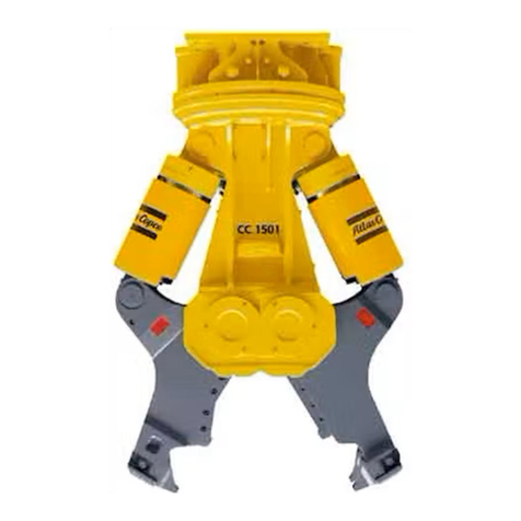
Atlas Copco CC 250 User manual

Operating instructions Combi cutter
CC 250 and CC 550
2009−07−10T.Id.Nr. 3390 5012 01


3
Operating instructions Combi cutter
CC 250
CC 550
EAtlas Copco Construction Tools GmbH
Atlas Copco Construction Tools GmbH
P. O. Box: 102152, D 45021 Essen
Helenenstrasse 149, D 45143 Essen
Federal Republic of Germany
Telephone: +49 201 633 0

4
Table of contents
1. Foreword 5. . . . . . . . . . . . . . . . . . . . . . . . . . . . . . . . . . . . . . . . . . . . . . . . . . . . . . . . . . . . . . . . . . .
2. Accident prevention regulations 6. . . . . . . . . . . . . . . . . . . . . . . . . . . . . . . . . . . . . . . . . . . . .
3. Marking according with machinery directive 98/37/EC 8. . . . . . . . . . . . . . . . . . . . . . . . .
3.1. CE−nameplate of product group Combi cutter 8. . . . . . . . . . . . . . . . . . . . . . . . . . . . . . . . . . .
4. General informations 9. . . . . . . . . . . . . . . . . . . . . . . . . . . . . . . . . . . . . . . . . . . . . . . . . . . . . . . .
4.1. Applications 9. . . . . . . . . . . . . . . . . . . . . . . . . . . . . . . . . . . . . . . . . . . . . . . . . . . . . . . . . . . . . . . .
4.2. Scope of supply 9. . . . . . . . . . . . . . . . . . . . . . . . . . . . . . . . . . . . . . . . . . . . . . . . . . . . . . . . . . . .
5. Main components 10. . . . . . . . . . . . . . . . . . . . . . . . . . . . . . . . . . . . . . . . . . . . . . . . . . . . . . . . . . .
5.1. Components of the Combi cutter CC 250 10. . . . . . . . . . . . . . . . . . . . . . . . . . . . . . . . . . . . . . .
5.2. Components of the Combi cutter CC 550 11. . . . . . . . . . . . . . . . . . . . . . . . . . . . . . . . . . . . . . .
6. Installation 12. . . . . . . . . . . . . . . . . . . . . . . . . . . . . . . . . . . . . . . . . . . . . . . . . . . . . . . . . . . . . . . . .
6.1. Media/consumables 12. . . . . . . . . . . . . . . . . . . . . . . . . . . . . . . . . . . . . . . . . . . . . . . . . . . . . . . . .
6.1.1. Mineral hydraulic oil 12. . . . . . . . . . . . . . . . . . . . . . . . . . . . . . . . . . . . . . . . . . . . . . . . . . . . . . . . .
6.1.2. Non−mineral hydraulic oil 12. . . . . . . . . . . . . . . . . . . . . . . . . . . . . . . . . . . . . . . . . . . . . . . . . . . . .
6.1.3. Grease 12. . . . . . . . . . . . . . . . . . . . . . . . . . . . . . . . . . . . . . . . . . . . . . . . . . . . . . . . . . . . . . . . . . . .
6.2. Transportation and storage 13. . . . . . . . . . . . . . . . . . . . . . . . . . . . . . . . . . . . . . . . . . . . . . . . . . .
6.3. Attaching the adapter to the Combi cutter 14. . . . . . . . . . . . . . . . . . . . . . . . . . . . . . . . . . . . . .
6.4. Mounting the Combi cutter on the excavator − mechanical aspects 15. . . . . . . . . . . . . . . . .
6.5. Mounting the Combi cutter on the excavator − hydraulic aspects 16. . . . . . . . . . . . . . . . . . .
6.6. Switching the Combi cutter on/off from the carrier 17. . . . . . . . . . . . . . . . . . . . . . . . . . . . . . .
6.7. Dismounting the Combi cutter from the excavator for short or lengthy periods of
nonuse 17. . . . . . . . . . . . . . . . . . . . . . . . . . . . . . . . . . . . . . . . . . . . . . . . . . . . . . . . . . . . . . . . . . .
7. Operating the Combi cutter 18. . . . . . . . . . . . . . . . . . . . . . . . . . . . . . . . . . . . . . . . . . . . . . . . . .
7.1. Start−up the Combi cutter 18. . . . . . . . . . . . . . . . . . . . . . . . . . . . . . . . . . . . . . . . . . . . . . . . . . . .
7.2. Functional test 18. . . . . . . . . . . . . . . . . . . . . . . . . . . . . . . . . . . . . . . . . . . . . . . . . . . . . . . . . . . . . .
7.3. Instructions on the correct use of the Combi cutter 19. . . . . . . . . . . . . . . . . . . . . . . . . . . . . .
7.4. Underwater applications 26. . . . . . . . . . . . . . . . . . . . . . . . . . . . . . . . . . . . . . . . . . . . . . . . . . . . .
7.5. Using the Combi cutter on cranes 26. . . . . . . . . . . . . . . . . . . . . . . . . . . . . . . . . . . . . . . . . . . . .
7.6. Working in high ambient temperature 26. . . . . . . . . . . . . . . . . . . . . . . . . . . . . . . . . . . . . . . . . .
7.7. Working in low ambient temperature 26. . . . . . . . . . . . . . . . . . . . . . . . . . . . . . . . . . . . . . . . . . .
7.8. Operating the Combi cutter with the cylinders fully extended or retracted 27. . . . . . . . . . .
8. Maintenance and care of the Combi cutter 27. . . . . . . . . . . . . . . . . . . . . . . . . . . . . . . . . . . .
8.1. General informations 27. . . . . . . . . . . . . . . . . . . . . . . . . . . . . . . . . . . . . . . . . . . . . . . . . . . . . . . .
8.2. Maintenance to be carried out by the carrier driver 28. . . . . . . . . . . . . . . . . . . . . . . . . . . . . . .
8.2.1. Lubrication of the Combi cutter 28. . . . . . . . . . . . . . . . . . . . . . . . . . . . . . . . . . . . . . . . . . . . . . .
8.2.2. Checking for cracks 29. . . . . . . . . . . . . . . . . . . . . . . . . . . . . . . . . . . . . . . . . . . . . . . . . . . . . . . . .
8.2.3. Checking the O−rings 30. . . . . . . . . . . . . . . . . . . . . . . . . . . . . . . . . . . . . . . . . . . . . . . . . . . . . . . .
8.2.4. Checking the blade clearance 30. . . . . . . . . . . . . . . . . . . . . . . . . . . . . . . . . . . . . . . . . . . . . . . .
8.2.5. Checking for wear 31. . . . . . . . . . . . . . . . . . . . . . . . . . . . . . . . . . . . . . . . . . . . . . . . . . . . . . . . . . .
8.2.6. Checking the hydraulic lines before starting work 31. . . . . . . . . . . . . . . . . . . . . . . . . . . . . . . .
8.2.7. Checking the adapter bolts for wear 31. . . . . . . . . . . . . . . . . . . . . . . . . . . . . . . . . . . . . . . . . . .
8.2.8. Checking and cleaning the hydraulic oil filter 31. . . . . . . . . . . . . . . . . . . . . . . . . . . . . . . . . . . .
8.2.9. Checking screw couplings 31. . . . . . . . . . . . . . . . . . . . . . . . . . . . . . . . . . . . . . . . . . . . . . . . . . . .
8.3. Maintenance / Tightening torques 32. . . . . . . . . . . . . . . . . . . . . . . . . . . . . . . . . . . . . . . . . . . . .
9. Troubleshooting 33. . . . . . . . . . . . . . . . . . . . . . . . . . . . . . . . . . . . . . . . . . . . . . . . . . . . . . . . . . . .
9.1. Combi cutter does not work 33. . . . . . . . . . . . . . . . . . . . . . . . . . . . . . . . . . . . . . . . . . . . . . . . . .
9.2. Combi cutter shows insufficient closing force 33. . . . . . . . . . . . . . . . . . . . . . . . . . . . . . . . . . .
9.3. Combi cutter does not cut 33. . . . . . . . . . . . . . . . . . . . . . . . . . . . . . . . . . . . . . . . . . . . . . . . . . . .
9.4. Operating pressure too high 33. . . . . . . . . . . . . . . . . . . . . . . . . . . . . . . . . . . . . . . . . . . . . . . . . .
9.5. Oil leaks from hydraulic ports 34. . . . . . . . . . . . . . . . . . . . . . . . . . . . . . . . . . . . . . . . . . . . . . . . .
9.6. Inadequate lubrication 34. . . . . . . . . . . . . . . . . . . . . . . . . . . . . . . . . . . . . . . . . . . . . . . . . . . . . . .
10. Disposal 34. . . . . . . . . . . . . . . . . . . . . . . . . . . . . . . . . . . . . . . . . . . . . . . . . . . . . . . . . . . . . . . . . . .
11. Lightweight, powerful, robust − Light−duty CCs. 34. . . . . . . . . . . . . . . . . . . . . . . . . . . . . . .
12. Technical specifications 35. . . . . . . . . . . . . . . . . . . . . . . . . . . . . . . . . . . . . . . . . . . . . . . . . . . . .
Index 36. . . . . . . . . . . . . . . . . . . . . . . . . . . . . . . . . . . . . . . . . . . . . . . . . . . . . . . . . . . . . . . . . . . . . . .

5
1. Foreword
Please read thisoperating manual beforeusing
your Atlas Copco Combi cutter for the first timeso
as to avoiderrorsand breakdowns through incor
rect usage.
These operating instructions contain:
Himportant safety regulations
Hoperating instructions for the Combi cutter
Hmaintenance instructions for the Combi cutter
Haids to troubleshooting
The operating instructions describe how to use the
Combi cutter on site and shouldthereforebe kept
inthe document compartment of the excavator
cab.
Please pay careful attention to the safety regula
tions which arelisted at the beginning of thisman
ual and repeated inthe relevant sections.
Responsibility for the observation of these safety
regulations lies at all times with the operator.
All safety regulations listed inthismanual comply
with the lawsand regulations of the European
Union. Additional national regulations have also
been taken into consideration wherever applicable.
Combi cutter operation outside the European Union
issubject to the lawsand regulations validinthe
countryof use. Morespecificnational regulations
and lawsthat applyinyour countrymust be obser
ved.
Please note that reliableoperation of the Combi
cutter can onlybe guaranteed ifgenuine spare
parts areused.
Wewish you everysuccess with your Combi cut
ter.
Atlas Copco Construction Tools GmbH

6
2. Accident prevention regulations
To avoid the risk of injury, please observe the fol
lowing instructions.
Familiarise yourself with the operating manual and
the applicable regulations before starting work with
the Combi cutter.
When using Combi cutter in states of the European
Union, the regulations contained in the EC machin
ery directive 98/37/EC must be observed and fol
lowed, as must all applicable national accident pre
vention regulations. In countries outside the
European Union, the valid local statutes and regula
tions shall apply. In countries outside of this zone
the corresponding general and specific laws and
regulations must be observed.
Explanation of the symbols used in this operating instructions
To emphasise their importance, certain points in the
operating instructions are marked with symbols,
which are described below.
DANGER!
Note!
The marked text provides instructions
on the correct use of the hydraulic tool
aimed at avoiding incorrect operation or
errors during work.
The marked text provides safety regula
tions and instructions aimed at avoiding
damage to equipment.
CAUTION!
The marked text provides safety regula
tions and instructions aimed at avoiding
accidents and possible injuries.

7
Before the first installation:
Beforemounting/dismounting the hydraulic tool
and/or any maintenancework on the hydraulics of
the hydraulic tool/carrier the hydraulic system must
be depressurized!
When using or transporting the carrier withthe
Combi cutter attached, the instructions included in
the operating manual supplied by the carrier
manufacturer must alsobe observed.
Do not run any hydraulic lines through the driver’s
cab sincethey may spring leaks or even burst.
During operations, the hydraulic oil becomes very
hot.
Mounting the Combi cutter:
Mounting the Combi cutter requires the presenceof
an assistant, who must be instructed by the carrier
driver. The carrier driver and assistant should agree
beforehand on clear hand signals.
For transport purposes, useonly the lugs provided
and hoisting equipment of sufficient capacity.
The Combi cutter should only be mounted on an
excavator withsufficient load capacity. The carriers
specified under Section 12., Te chnical specifications
areneeded toinstall the Combi cutter.
Carriers below this weight class will not provide the
required degree of stability and could even fall over
during Combi cutter use, causing injury and damage.
Carriers abovethis weight class may apply
excessively high mechanical loads tothe attachment.
When attaching the adapter useonly the special
steel screws included in supply.
Check the nominal widthof the hydraulic lines on
existing hydraulic systems. It is important that supply
and returnlines for the hydraulic oil areadequately
dimensioned.
Keep your hands away from bores and fitting
surfaces when mounting the Combi cutter, especially
when the carrier boom is moving.
Collect any oil whichruns out and disposeof it in
accordancewiththe applicable statutory provisions
toavoid environmental hazards.
Operating the Combi cutter:
Closethe front screen/splinter guardon the driver’s
cab toprotect the driver from flying rock splinters
during Combi cutter operations.
The Combi cutter should only be operated from the
driver’s cab. Exception: remotecarrier control. See
Section 6.6..
Do not start up the Combi Cutter until bothcarrier
and Combi cutter arein the correct position.
Stop the Combi cutter immediately as soon as
persons arein the danger zone. The danger zone
during the Combi cutter operation is considerably
greater than during the excavation operation − on
account of fractions of stones and pieces of steel
flying around − and for this reason, the danger zone
must, depending on the type of material tobe worked
on, be enlarged correspondingly, or the danger zone
must be secured in asuitable manner through
corresponding measures.
Do not touch any hot parts
The Combi cutter heats up during operation.
Monitor the oil temperature
The temperatureof the hydraulic oil must never
exceed 80 oC. If higher temperatures aremeasured
in the tank, the hydraulic system and/or the
pressure−relief valvehavetobe checked.
Observethe excavator manufacturer’s safety
regulations.
CAUTION:
Withregardtoexcavator operation when working
withan attached Combi cutter, pleaserefer to
Section 6.6..
The Combi cutter is only tobe used for the
applications described.
Dismounting the Combi cutter:
Dismounting the Combi cutter from the carrier
requires the presenceof an additional assistant who
must be instructed by the carrier driver. The carrier
driver and assistant should agree beforehand on
clear hand signals.
When using the excavator or putting it out of
operation, the safety instructions of the excavator
manufacturer must be observed.
Keep your hands away from bores and fitting
surfaces when dismounting the Combi cutter,
especially when the carrier boom is moving.
Collect any oil whichruns out and disposeof it in
accordancewiththe applicable statutory provisions
toavoid environmental hazards.
Securethe Combi cutter after dismounting sothat it
cannot fall over.

8
3. Marking according with machinery directive 98/37/EC
CE−nameplate
Fig. 1
3.1. CE−nameplate of product group Combi cutter
Name and address of manufacturer
Model
Serial no.
Weight of product group
.Max. operating pressure
.Year of construction of product group
Atlas Copco Construction Tools
Essen Germany
Made in Germany
Type
Ser. No.
Deliv. wt
P max
Year
The CE nameplatecontains information on the
Combi cutter. The weight indicated refer tothe
weight of the Combi cutter.
When selecting hoists and suspension aids for
transporting the unit, the weight of the and adapter
may alsohavetobe considered.
Inaccording withEC directives CE nameplates must
be affixed firmly and in aclearly visible position.
Should thesenameplates be lost or defaced,
replacements can be ordered from your dealer/from
Atlas CopcoConstruction Tools GmbH.

9
4. General informations
4.1. Applications
The Combi cutter is an attachment suitable for
mounting on hydraulicpowered excavators.
The Combi cutter has been suited for the following
operations:
light demolition work, e. g. narrow, lightly reinforced
concreteelements, masonry
particularly effectivefor stripping out and
reconstructing interiors
CAUTION!
Incorrect operation may result in damage tothe
Combi cutter and tothe equipment of the excavator.
Under normal circumstances the Combi cutter is
operated from the driver’s cab of the carrier.
Pleaserefer toSections 2.and 6.6..
4.2. Scope of supply
The scope of supply of aCombi cutter generally
includes:
Combi cutter, operating instructions, spareparts list
and EC declaration of conformity.
Accessories: hoses according tothe order.
Special accessories: e. g. adapter, hydraulic adapter
kit for the excavator according tothe order.

10
5. Main components
5.1. Components of the Combi cutter CC 250
Fig. 2
CC 250
A
B360
1100
Ports
A+C
Table of dimensions
Port A = opening
Port C = closing
R1/2"
B
A
Mounting platefor
adapter
Cylinder
Cutter casing
Cutter jaw

11
5.2. Components of the Combi cutter CC 550
Fig. 3
CC 550
A
B450
1325
Ports
A+C
1/2" SAE
6000 PSI
Table of dimensions
Port A = opening
Port C = closing
B
A
Mounting platefor
adapter
Cutter casing
Cylinder
Cutter jaw

12
6. Installation
6.1. Media/consumables
Operating the Combi cutter requires the following
resources:
6.1.1. Mineral hydraulic oil
All hydraulic oil brands prescribed by the carrier
manufacturer aresuitable for operating the Combi
cutter.
The oil should however correspond toviscosity class
HLP 32 or higher.
Insummer and in hotter climates, oils of viscosity
class HLP 68 or higher should be used.
Inall other respects the regulations of the carrier
manufacturer aretobe considered.
Optimum viscosity range = 30 60 cSt
Max. initial viscosity = 2000 cSt
Max. oil temperature= 80oC
Pleaserefer tosection 7.7.. for low−temperature
Combi cutter applications.
Check the oil filter.
An oil filter has tobe installed in the returnline of the
hydraulic system. The meshwidthof this filter should
not exceed 50 micrometers and amagnetic
separator must be fitted.
CAUTION!
Monitor the oil temperature.
The temperatureof the hydraulic oil must never
exceed 80oC. If higher temperatures aremeasured
in the tank, the hydraulic system and/or the
pressure−relief valvehavetobe checked.
6.1.2. Non−mineral hydraulic oil
Inorder toprotect the environment or on technical
grounds, hydraulic oils arecurrently being used
whicharenot classified as HLP mineral oils.
Beforeusing hydraulic oils of this kind it is imperative
toenquirewiththe carrier manufacturer whether
operations withsuchfluids arepossible.
Our tools arebasically designed for usewithmineral
oils. Beforeusing other fluid types whichhavebeen
approved by the carrier manufacturer, always consult
the Atlas CopcoCustomer Center/Dealer in your
area. Following initial assembly and after any
workshop repairs, our tools aresubjected toatest
run on atest bed powered by mineral oil.
Note!
When returning tools for repair, it is imperativethat
the name of the oil in usebe indicated if you are
using non−mineral oil.
CAUTION!
Never mix mineral and non−mineral hydraulic oils!
Even small traces of mineral oil mixed in with
non−mineral hydraulic oil can result in damage to
bothhydraulic attachment and carrier.
CAUTION!
Non−mineral oil is no longer biodegradable if it is
contaminated withmineral oil. Contaminated
non−mineral oil must be disposed of as special waste
in accordancewiththe applicable statutory
regulations for environmental protection.
6.1.3. Grease
ÂÂÂÂÂÂÂÂ
Â
ÂÂÂÂÂÂ
Â
ÂÂÂÂÂÂÂÂ
Agents/consumables
ÂÂÂÂÂÂÂÂÂ
Â
ÂÂÂÂÂÂÂ
Â
ÂÂÂÂÂÂÂÂÂ
Part ID No.
Cutter grease 3363 0949 14
Always observethe relevant safety regulations when
handling oils and greases.

13
6.2. Transportation and storage
DANGER!
Usethe provided lugs and hoisting gear of adequate
carrying capacity tolift the Combi cutter! (see Fig. 4)
Ropes and lug must be in good condition.
The Combi cutter should be deposited on awooden
support of sufficient sizeand strength.
Oil may run out of the hydraulic connections when
removed. Collect any oil whichruns out and dispose
of it in accordancewiththe applicable statutory
provisions toavoid environmental hazards. Closeoff
all open lines!
Always observethe relevant safety regulations when
handling oils and greases.
Fig. 4
Turnthe mounting plateintothe correct position.
Insert and securethe hinge−pins. Makesurethat the
hinge−pins areinserted properly sothat the mounting
platedoes not turnor rotateduring transportation.
(see fig. 5)
Fig. 5

14
CAUTION!
To avoid damage tothe piston rods of the hydraulic
cylinders when transporting the Combi cutter, the
piston rods must be retracted, i. e. the Combi cutter
must be in open" position.
6.3. Attaching the adapter to the Combi cutter
Deposit the Combi cutter on squared beams or
pallets within reachof the carrier boom.
Bolt the adapter tothe Combi cutter’s mounting plate
swivel or mounting plate.
DANGER!
Useonly the special steel screws included in supply.
When transporting the cutter useonly the transport
lug provided and sufficiently powerful lifting
equipment. Notethe weight (name plate, section
3.1.)
Notefor anyone using this operating manual:
Figures marked withKdo not correspond exactly to
the CC 250 and CC 550 Combi cutter models, but
areonly intended todepict the process described.
K Fig. 6
Adapter

15
6.4. Mounting the Combi cutter on the excavator − mechanical aspects
DANGER!
Only mount the Combi cutter on an excavator with
sufficient load capacity. If the excavator is too
light it may become unstable and fall over.
The operator of the carrier must remain in the
driver’s seat when the Combi cutter is being installed.
Agree withthe assistant on clear hand signals. The
assistant must be instructed by the excavator driver.
Keep your hands away from bores and fitting
surfaces when mounting the Combi cutter.
Do not touchany parts when the boom is moving.
Never useyour fingers tocheck whether the bores
areflush.
Oncethe adapter has been attached, position the
Combi cutter facing the carrier boom (stick) as
shown in Figs 7and 8. Inthis way the stick of the
excavator boom can be moved intothe adapter in
suchaway that the bores in the stick/adapter are
aligned.
Insert stick pin and secureas shown in Fig. 7.
Fig. 7K

16
To fit the toggle pin, extend the shovel cylinder and
position the toggle by hand until the bores are
aligned withthosein the adapter. Insert toggle pin
and secure.
KFig. 8
CAUTION!
After installing the Combi cutter, carefully drivethe
bucket cylinder tobothend positions. The cylinder
must travel smoothly and without hindrancetoboth
end positions without striking the adapter (unless the
adapter is fitted withan end stop).
6.5. Mounting the Combi cutter on the excavator − hydraulic aspects
DANGER!
Before mounting/dismounting the hydraulic tool
and/or any maintenance work on the hydraulics
of the hydraulic tool/carrier the hydraulic system
must be depressurized.
The excavator must haveahydraulic system suitable
for Combi cutter operations.
Check the nominal widthof the hydraulic lines on
existing hydraulic systems. All feed and returnlines
for the hydraulic oil must haveasufficient inside
diameter. Refer toSection 12., Te chnical
specifications.
Useonly hoses/pipes whichsatisfy the following
quality criteria:
Hydraulic hoses with4wirespiral layers toDIN
20023. Hydraulic pipes: seamless, cold drawn steel
pipes toDIN2391, page 2, grade C. Hydraulic pipes:
seamless, cold drawn steel pipes toDIN2391, page
2, grade C.
Check the pressurerelief valveon the hydraulic
system.
The pressure−relief valvemust be set tothe
maximum permissible pressure, see Section 12.,
Technical specifications. For reasons of liability we
recommend subsequent lead of the valve.
The pressure−relief overflow line must run direct from
the pressure−relief valvetothe tank toensurethe
reliable functioning of the valve.
Do not run any hydraulic lines through the driver’s
cab.
Hydraulic lines may spring aleak or even burst,
releasing hot hydraulic oil.
Detachthe screw caps from the connections, and
keep them in asafeplace.
Check the connecting threads on the Combi cutter
ports and the corresponding hoseconnectors to
ensurethey areundamaged. Sand or other foreign
bodies in the threads must be cleaned away.
Screw the hoses tothe ports. (Tightening torques
see section 8.3.)
Inthe interests of safety, if you come tothe
conclusion that the system does not comply withthe
requirements listed above, always consult the Atlas
CopcoCustomer Center/Dealer in your area.

17
If thereis no corresponding installation site, the
original conversion kit must be attached. Thereare
special instructions for this installation type.
When connecting or reconnecting the hydraulic lines,
the carrier must be secured in suchaway that
automatic startup of the Combi cutter is reliably
avoided.
If no genuine conversion kit has been used on the
hydraulic system, check that the ports on the
excavator matchthe Combi cutter hoseconnectors.
Refer toSection 12., Te chnical specifications.
6.6. Switching the Combi cutter on/off from the carrier
The installation of agenuine conversion kit in the
carrier’s hydraulic system allows the Combi cutter to
be powered using the carrier hydraulics. All functions
for normal excavator operations remain intact. The
Combi cutter is switched on/off via electrical signals.
When leaving the driver’s cab, the safety switchfor
theseelectrical signals must be set to"OFF" position
soas toreliably prevent any unintended
startup of the Combi cutter.
Bothcarrier and Combi cutter can be operated by
remotecontrol. For further details pleasecontact the
carrier manufacturer and/or the Atlas Copco
Customer Center/Dealer in your area.
6.7. Dismounting the Combi cutter from the excavator for
short or lengthy periods of nonuse
Before mounting/dismounting the hydraulic tool
and/or any maintenance work on the hydraulics
of the hydraulic tool/carrier the hydraulic system
must be depressurized.
For safety reasons, the carrier must be switched
off before performing the following work.
Unless otherwisestipulated, the Combi cutter is
dismounted in reverseorder tomounting.
Open the Combi cutter’s jaws tothe full extent so
that the piston rods lie fully retracted in the hydraulic
cylinders.
Deposit the Combi cutter on squared beams or
pallets away from other transport routes.
Seal off all open hoseconnections.
Turnthe mounting plateintothe correct position.
Insert and securethe hinge−pins. Makesurethat the
hinge−pins areinserted properly sothat the mounting
platedoes not turnor rotateduring transportation.
Unlock the toggle and stick pins and knock out the
pins using asteel rod and ahammer.
Cover up the Combi cutter toprotect it against the
weather.
DANGER!
Collect any oil whichruns out and disposeof it in
accordancewiththe applicable statutory provisions
toavoid environmental hazards.
Agree on hand signals withthe assistant.
Keep your hands away from bores and fitting
surfaces when dismounting the Combi cutter.
Do not touchany parts when the boom is moving.
Observethe excavator manufacturer’s safety
regulations.
When putting the excavator out of operation, please
observethe excavator manufacturer’s instructions.

18
7. Operating the Combi cutter
7.1. Start−up the Combi cutter
First of all, precautionary measures should be taken
torule out the risk of accidents.
DANGER!
Only operatethe Combi cutter from the driver’s seat
in the excavator cab.
Closethe front screen / splinter guardon the driver’s
cab toavoid injury from flying rock splinters.
Stop the Combi cutter immediately as soon as
persons are in the danger zone. The danger zone
during the Combi cutter operation is
considerably greater than during the excavation
operation − on account of fractions of stones and
pieces of steel flying around − and for this
reason, the danger zone must, depending on the
type of material to be worked on, be enlarged
correspondingly, or the danger zone must be
secured in a suitable manner through
corresponding measures.
7.2. Functional test
Using the carrier boom raisethe Combi cutter until it
is suspended vertically.
First functional test: opening − closing
The cutter jaws areopened and closed by actuating
the switchin the leg−spacearea of the cab.
Second functional test: Rotatetothe left and right
stops
The Combi cutter is swivelled mechanically when a
jaw comes up against astationary object.

19
7.3. Instructions on the correct use of the Combi cutter
The Combi cutter must be used exclusively for the
work listed under subsection 4.1.. Inthe following a
number of examples show how the Combi cutter is
operated properly.
The depictions arenot intended toreproducethe
Combi cutters, but toillustratethe circumstances
described.
CAUTION!
KFig. 9
The hydraulic cylinders on
the carrier boom must not
be retracted totheir full ex
tent, sincethis could result
in damage tobothcarrier
and Combi cutter.
KFig. 10
CAUTION!
The hydraulic cylinders
on the carrier boom
must not be extended to
their full extent, since
this could result in dam
age tobothcarrier and
Combi cutter.

20
Instructions on the correct use of the Combi cutter
DANGER!
KFig. 11
Ensurethat the carrier is
positioned on firmground. If
this is not the case, the car
rier may fall over.
DANGER!
KFig. 12
When working on floors/
roofs, ensurethat they are
strong enough tobear the
weight of the carrier.
Danger of collapse!
This manual suits for next models
1
Table of contents
Other Atlas Copco Cutter manuals