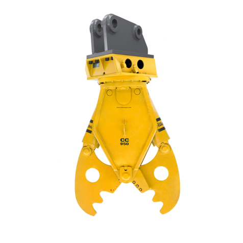
Atlas Copco CombiCutter CC 1501 User manual

Operating instructions CombiCutter
hydraulic cutter
CC 1501, CC 2100 and CC 4000
Valid from: 07/2003 GBT.Id.Nr. 3363 0028 88
CC 2100


3
Operating instructions CombiCutter
hydraulic cutter
CC 1501
CC 2100
CC 4000
E Atlas Copco Co structio Tools GmbH
Atlas Copco Construction Tools GmbH
P. O. Box: 102152, D 45021 Esse
Hele e strasse 149, D 45143 Esse
Federal Republic of Germa y
Telepho e: +49 201 633 0
Telefax: +49 201 633 2281
Telefax Customer Support: +49 201 633 1352

4
oreword
Please read this operati g ma ual before usi g
your Atlas Copco CombiCutter for the first time so
as to avoid errors a d breakdow s through i cor
rect usage.
These operati g i structio s co tai :
Himporta t safety regulatio s
Hoperati g i structio s for the hydraulic cutter
Hmai te a ce i structio s for the hydraulic cutter
Haids to troubleshooti g
The operati g i structio s describe how to use the
hammer o site a d should therefore be kept i the
docume t compartme t of the excavator cab.
Please pay careful atte tio to the safety regula
tio s which are listed at the begi i g of this ma
ual a d repeated i the releva t sectio s.
Respo sibility for the observatio of these safety
regulatio s lies at all times with the operator.
All safety regulatio s listed i this ma ual comply
with the laws a d regulatio s of the Europea
U io . Additio al atio al regulatio s have also
bee take i to co sideratio wherever applicable.
Hydraulic cutter operatio outside the Europea
U io is subject to the laws a d regulatio s valid i
the cou try of use.
Please ote that reliable operatio of the hydraulic
cutter ca o ly be guara teed if ge ui e spare
parts are used.
We wish you every success with your hydraulic
cutter.
Atlas Copco Construction Tools GmbH

5
Explanation of the symbols used in this operating manual
Certai i structio s i the operati g ma ual are marked with symbols to emphasise
their importa ce.
The symbols used are described below:
CAUTION!
Please note!
The marked text provides i structio s
o the correct use of the hydraulic tool
aimed at avoidi g i correct operatio or
errors duri g work.
The marked text provides safety regula
tio s a d i structio s aimed at avoiding
damage to equipment.
WARNING!
The marked text provides safety regula
tio s a d i structio s aimed at avoiding
accidents and possible injuries.

6
Table of contents
oreword 4 . . . . . . . . . . . . . . . . . . . . . . . . . . . . . . . . . . . . . . . . . . . . . . . . . . . . . . . . . . . . . . . . . . .
1. Accident prevention regulations 8 . . . . . . . . . . . . . . . . . . . . . . . . . . . . . . . . . . . . . . . . . . . . .
2. Identifying the hydraulic cutter 10 . . . . . . . . . . . . . . . . . . . . . . . . . . . . . . . . . . . . . . . . . . . . . . .
2.1. Scope of supply 10 . . . . . . . . . . . . . . . . . . . . . . . . . . . . . . . . . . . . . . . . . . . . . . . . . . . . . . . . . . . .
3. CE markings (EU directive on machinery 98/37/EC) 11 . . . . . . . . . . . . . . . . . . . . . . . . . . .
4. Technical specifications 12 . . . . . . . . . . . . . . . . . . . . . . . . . . . . . . . . . . . . . . . . . . . . . . . . . . . . .
5. Applications 13 . . . . . . . . . . . . . . . . . . . . . . . . . . . . . . . . . . . . . . . . . . . . . . . . . . . . . . . . . . . . . . . .
6. Transportation and storage 13 . . . . . . . . . . . . . . . . . . . . . . . . . . . . . . . . . . . . . . . . . . . . . . . . . .
7. Main components 14 . . . . . . . . . . . . . . . . . . . . . . . . . . . . . . . . . . . . . . . . . . . . . . . . . . . . . . . . . . .
8. Mounting the hydraulic cutter 15 . . . . . . . . . . . . . . . . . . . . . . . . . . . . . . . . . . . . . . . . . . . . . . . .
8.1. Co ecti g the cutter to the carrier’s hydraulic system 15 . . . . . . . . . . . . . . . . . . . . . . . . . . .
8.1.1. Co ecti g for the first time 15 . . . . . . . . . . . . . . . . . . . . . . . . . . . . . . . . . . . . . . . . . . . . . . . . . .
8.1.2. Co verti g from hammer operatio to cutter operatio 15 . . . . . . . . . . . . . . . . . . . . . . . . . . .
8.1.3. Checki g existi g hydraulic facility for cutter operatio 15 . . . . . . . . . . . . . . . . . . . . . . . . . . .
8.2. Mecha ical attachme t 16 . . . . . . . . . . . . . . . . . . . . . . . . . . . . . . . . . . . . . . . . . . . . . . . . . . . . . .
8.2.1. Attachi g the adapter to the hydraulic cutter 16 . . . . . . . . . . . . . . . . . . . . . . . . . . . . . . . . . . . .
8.2.2. Mou ti g the hydraulic cutter o the carrier 17 . . . . . . . . . . . . . . . . . . . . . . . . . . . . . . . . . . . . .
9. Operating the hydraulic cutter 18 . . . . . . . . . . . . . . . . . . . . . . . . . . . . . . . . . . . . . . . . . . . . . . .
9.1. Media/co sumables 18 . . . . . . . . . . . . . . . . . . . . . . . . . . . . . . . . . . . . . . . . . . . . . . . . . . . . . . . . .
9.1.1. Mi eral hydraulic fluids 18 . . . . . . . . . . . . . . . . . . . . . . . . . . . . . . . . . . . . . . . . . . . . . . . . . . . . . .
9.1.2. E viro me t−frie dly fluids 18 . . . . . . . . . . . . . . . . . . . . . . . . . . . . . . . . . . . . . . . . . . . . . . . . . . .
9.2. Start−up 19 . . . . . . . . . . . . . . . . . . . . . . . . . . . . . . . . . . . . . . . . . . . . . . . . . . . . . . . . . . . . . . . . . . . .
9.3. Fu ctio al test 19 . . . . . . . . . . . . . . . . . . . . . . . . . . . . . . . . . . . . . . . . . . . . . . . . . . . . . . . . . . . . . .
9.4. Limitatio s whe cutti g steel 20 . . . . . . . . . . . . . . . . . . . . . . . . . . . . . . . . . . . . . . . . . . . . . . . . .
9.5. I structio s o the correct use of the hydraulic cutter 20 . . . . . . . . . . . . . . . . . . . . . . . . . . . .
9.6. U derwater applicatio s 27 . . . . . . . . . . . . . . . . . . . . . . . . . . . . . . . . . . . . . . . . . . . . . . . . . . . . .
10. Care and maintenance of the hydraulic cutter 28 . . . . . . . . . . . . . . . . . . . . . . . . . . . . . . . . .
10.1. Ge eral i formatio 28 . . . . . . . . . . . . . . . . . . . . . . . . . . . . . . . . . . . . . . . . . . . . . . . . . . . . . . . . .
10.2. Mai te a ce work 28 . . . . . . . . . . . . . . . . . . . . . . . . . . . . . . . . . . . . . . . . . . . . . . . . . . . . . . . . . .
10.2.1. Mai te a ce work to be performed by the carrier driver 28 . . . . . . . . . . . . . . . . . . . . . . . . . .
10.3. Care a d replaceme t of cutter blades 29 . . . . . . . . . . . . . . . . . . . . . . . . . . . . . . . . . . . . . . . . .
10.4. Checki g a d correcti g the blade cleara ce 30 . . . . . . . . . . . . . . . . . . . . . . . . . . . . . . . . . . .
10.5. Replaci g the cutter teeth 32 . . . . . . . . . . . . . . . . . . . . . . . . . . . . . . . . . . . . . . . . . . . . . . . . . . . .
10.6. Weldi g i structio s for cutter jaws a d teeth 33 . . . . . . . . . . . . . . . . . . . . . . . . . . . . . . . . . . .
10.7. Prese tatio − Cutter jaw 34 . . . . . . . . . . . . . . . . . . . . . . . . . . . . . . . . . . . . . . . . . . . . . . . . . . . . .
10.7.1. Prese tatio − Cutter jaw CC 1501 U (si gle) 34 . . . . . . . . . . . . . . . . . . . . . . . . . . . . . . . . . . .

7
10.7.2. Prese tatio − Cutter jaw CC 1501 U (double) 35 . . . . . . . . . . . . . . . . . . . . . . . . . . . . . . . . . .
10.7.3. Prese tatio − Cutter jaw CC 1501 S (double) 35 . . . . . . . . . . . . . . . . . . . . . . . . . . . . . . . . . . .
10.7.4. Prese tatio − Cutter jaw CC 2100 U (si gle) 36 . . . . . . . . . . . . . . . . . . . . . . . . . . . . . . . . . . .
10.7.5. Prese tatio − Cutter jaw CC 2100 U (double) 36 . . . . . . . . . . . . . . . . . . . . . . . . . . . . . . . . . .
10.7.6. Prese tatio − Cutter jaw CC 2100 S (double) 37 . . . . . . . . . . . . . . . . . . . . . . . . . . . . . . . . . . .
10.7.7. Prese tatio − Cutter jaw CC4000 U (si gle) 37 . . . . . . . . . . . . . . . . . . . . . . . . . . . . . . . . . . . .
10.7.8. Prese tatio − Cutter jaw CC 4000 U (double) 38 . . . . . . . . . . . . . . . . . . . . . . . . . . . . . . . . . .
10.7.9. Prese tatio − Cutter jaw CC 4000 S (double) 38 . . . . . . . . . . . . . . . . . . . . . . . . . . . . . . . . . . .
10.7.10. Prese tatio − Cutter jaw CC 1501 S (si gle) 39 . . . . . . . . . . . . . . . . . . . . . . . . . . . . . . . . . . .
10.7.11. Prese tatio − Cutter jaw CC 2100 S (si gle) 40 . . . . . . . . . . . . . . . . . . . . . . . . . . . . . . . . . . .
10.7.12. Prese tatio − Cutter jaw CC4000 S (si gle) 40 . . . . . . . . . . . . . . . . . . . . . . . . . . . . . . . . . . . .
10.8. Mai te a ce schedule 41 . . . . . . . . . . . . . . . . . . . . . . . . . . . . . . . . . . . . . . . . . . . . . . . . . . . . . . .
10.9. Lubrica t recomme datio s 43 . . . . . . . . . . . . . . . . . . . . . . . . . . . . . . . . . . . . . . . . . . . . . . . . . .
10.9.1. Prese tatio − Lubricatio poi ts o the hydraulic cutters
CC 1501, CC 2100 a d CC 4000 43 . . . . . . . . . . . . . . . . . . . . . . . . . . . . . . . . . . . . . . . . . . . . . .
11. Troubleshooting 44 . . . . . . . . . . . . . . . . . . . . . . . . . . . . . . . . . . . . . . . . . . . . . . . . . . . . . . . . . . . .
11.1. Hydraulic cutter does ot work 44 . . . . . . . . . . . . . . . . . . . . . . . . . . . . . . . . . . . . . . . . . . . . . . . .
11.2. I sufficie t breaki g force 44 . . . . . . . . . . . . . . . . . . . . . . . . . . . . . . . . . . . . . . . . . . . . . . . . . . . .
11.3. Hydraulic cutter does ot cut 44 . . . . . . . . . . . . . . . . . . . . . . . . . . . . . . . . . . . . . . . . . . . . . . . . .
11.4. Hydraulic cutter ca ot be rotated 45 . . . . . . . . . . . . . . . . . . . . . . . . . . . . . . . . . . . . . . . . . . . . .
11.5. Operati g temperature too high 45 . . . . . . . . . . . . . . . . . . . . . . . . . . . . . . . . . . . . . . . . . . . . . . .
11.6. Oil leaks from hydraulic ports 45 . . . . . . . . . . . . . . . . . . . . . . . . . . . . . . . . . . . . . . . . . . . . . . . . .
11.7. I sufficie t lubricatio 45 . . . . . . . . . . . . . . . . . . . . . . . . . . . . . . . . . . . . . . . . . . . . . . . . . . . . . . .
12. Dismounting the hydraulic cutter 46 . . . . . . . . . . . . . . . . . . . . . . . . . . . . . . . . . . . . . . . . . . . .
12.1. Shutdow 46 . . . . . . . . . . . . . . . . . . . . . . . . . . . . . . . . . . . . . . . . . . . . . . . . . . . . . . . . . . . . . . . . . .

8
1. Accident prevention regulations
Caution!
To avoid the risk of i jury, please observe the
followi g i structio s.
Before starting work:
Familiarise yourself with the operati g ma ual a d
the applicable regulatio s before starti g work with
the hydraulic cutter.
Whe usi g hydraulic cutters i states of the
Europea U io , the regulatio s co tai ed i the EC
machi ery directive 98/37/EC must be observed a d
followed, as must all applicable atio al accide t
preve tio regulatio s.
I cou tries outside the Europea U io , the valid
local statutes a d regulatio s shall apply.
Whe tra sporti g the carrier with the hydraulic
cutter attached, the carrier ma ufacturer’s safety
i structio s shall apply.
Mounting the hydraulic cutter:
Check the omi al width of the hydraulic li es o
existi g hydraulic systems. All feed a d retur li es
for the hydraulic oil must have a adequate i side
diameter. (Refer to Sectio 4 "Tech ical
Specificatio s").
Use o ly hoses/pipes which satisfy the followi g
quality criteria:
Hydraulic hoses with 4 wire spiral layers to
DIN 20023.
Hydraulic pipes: seamless, cold draw steel pipes to
DIN 2391, page 2, grade C.
Check the ports o the hydraulic cutter a d the hose
co ectio s. The threads must be free of damage.
Clea off a y sa d or similar foreig bodies i the
threads.
Do ot ru a y hydraulic li es through the driver’s
cab.
Mou ti g the hydraulic cutter requires the prese ce
of a assista t, who must be i structed by the carrier
driver. The carrier driver a d assista t should agree
beforeha d o clear ha d sig als.
For tra sport purposes, use o ly the lug provided
a d hoisti g equipme t of sufficie t capacity.
The hydraulic cutter should o ly be mou ted o a
carrier with sufficie t load capacity. For Atlas Copco
hydraulic cutters this ormally mea s a carrier as
show i the table below:
ÂÂÂÂÂÂÂÂ
Â
ÂÂÂÂÂÂ
Â
ÂÂÂÂÂÂÂÂ
Cutter model
ÂÂÂÂÂÂÂÂÂ
Â
ÂÂÂÂÂÂÂ
Â
ÂÂÂÂÂÂÂÂÂ
Carrier weight class
CC 1501
CC 2100
CC 4000
15 − 25 t
22 − 35 t
35 − 50 t
Check the pressure relief valve for the cutter circuit
o the hydraulic system to e sure it is set exactly to
the refere ce value.
Caution!
Collect a y oil which ru s out a d dispose of it
correctly.
The oil ca be very hot, risk of burns!
Cutter operation:
Before fitting and removing the hydraulic cutter
and/or performing service work on the cutter or
carrier hydraulics, ensure that the hydraulic
system has been depressurized!
(see section 10)
Observe the carrier ma ufacturer’s safety regulatio s
Whe worki g with a hydraulic cutter, carrier
operatio is gover ed by the carrier ma ufacturer’s
i structio s.
The hydraulic cutter may o ly be used for the
applicatio s described.
Close the fro t scree /spli ter guard o the driver’s
cab to protect the driver from flyi g rock spli ters
duri g cutter operatio s.
The hydraulic cutter should o ly be operated from
the driver’s cab.
Do ot start up the hydraulic cutter u til both carrier
a d hydraulic cutter are i the correct positio .
If the cutter is to be used i or u der water, prior
co sultatio with Atlas Copco’s Customer Support is
ecessary to clarify the special requireme ts for such
applicatio s.
Use o ly approved hydraulic oils.
All mi eral hydraulic oil bra ds prescribed by the
carrier ma ufacturer are suitable for cutter operatio .
The use of other hydraulic fluids is subject to prior
co sultatio .
Use o ly hydraulic oils of sufficie t viscosity.
I summer a d i tropical climates, oils of viscosity
class HLP 68 or higher should be used.
Observe the oil temperature at all times.
The temperature of the hydraulic oil must ever
exceed 80oC.
Do ot start up the hydraulic cutter at temperatures
below mi us 20oC u til the hydraulic oil has bee
warmed up.
Caution!
Stop the hydraulic cutter immediately if a yo e
moves i to the da ger zo e, i. e. a radius of at least
7 metres arou d the hydraulic cutter.

9
Depe di g o the applicatio a d the material
greater dista ces may have to be observed or the
site must be cordo ed off.
Danger by flying splinters!
Maintenance and repairs:
Before fitting and removing the hydraulic cutter
and/or performing service work on the cutter or
carrier hydraulics, ensure that the hydraulic
system has been depressurized!
(see section 10)
Use Atlas Copco cutter grease to lubricate the tool.
Observe the mai te a ce schedule a d carry out all
the preve tive checks listed.
Dismou ti g the hydraulic cutter:
Dismou ti g the hydraulic cutter requires the
prese ce of a assista t, who must be i structed by
the carrier driver. The carrier driver a d assista t
should agree beforeha d o clear ha d sig als.
Observe the carrier ma ufacturer’s safety
regulatio s.
Whe putti g the carrier out of operatio , the carrier
ma ufacturer’s i structio s shall apply.
Caution!
Collect a y oil which ru s out a d dispose of it
correctly.
Please note:
The oil ca be very hot. Risk of bur s!
Please note:
After cutter operatio , oil−beari g parts are very hot.
Risk of bur s!
After dismou ti g store the cutter i such a way that
it ca ot fall over.

10
2. Identifying the hydraulic cutter
The ameplate (see Fig. 1 for locatio ) provides the followi g i formatio ide tifyi g the cutter:
Hma ufacturer
Hhydraulic cutter model
Hweight
Hyear built
Hpart ide t. o.
Please note: The serial umber is stamped o to the cutter below the lifti g lug.
These data should be quoted i all correspo de ce − especially whe orderi g spare parts − so as to clearly
ide tify the cutter.
Fig. 1
CC 2100
Nameplate
2.1. Scope of supply
The ge eral scope of supply for a Atlas Copco CombiCutter i cludes:
Hhydraulic cutter
Hoperati g ma ual
Hspare parts list
Hi fo. sheet
Hspecial accessories as ordered, e.g. hydraulic
co versio kit for carrier, adapter
Subject to modificatio .

11
3. CE markings
(EU directive on machinery 98/37/EC)
CC 2100
Locatio of CE ameplate:
Lower face of slewi g ri g
Fig. 2
Warning:
I accordi g with EC directives CE ameplates must be affixed firmly a d i a clearly visible positio . Should
these ameplates be lost or defaced, replaceme ts ca be ordered from your dealer /Atlas Copco
Co structio Tools.
The followi g i formatio must be provided:
Part ide t. o./ser. o. of the tool a d date of delivery (from the delivery ote)
1. Name a d address of ma ufacturer
2. Model
3. Serial o.
4. Part ide t. o.
5. Max. permissible operati g pressure
6. Year of ma ufacture of product group
7. Weight of product group
CE nameplate
1
2
3
4
5
6
7

12
4. Technical specifications
ÂÂÂÂÂÂÂÂÂÂÂ
Â
ÂÂÂÂÂÂÂÂÂ
Â
ÂÂÂÂÂÂÂÂÂÂÂ
Model
ÂÂÂÂÂÂÂÂ
Â
ÂÂÂÂÂÂ
Â
ÂÂÂÂÂÂÂÂ
CC 1501
ÂÂÂÂÂÂÂÂ
Â
ÂÂÂÂÂÂ
Â
ÂÂÂÂÂÂÂÂ
CC 2100
ÂÂÂÂÂÂÂÂÂ
Â
ÂÂÂÂÂÂÂ
Â
ÂÂÂÂÂÂÂÂÂ
CC 4000
Type U S U S U S
Weight K[kg] 1860 1850 2740 2690 4380 4220
Recomme ded
carrier class [ t ] 15 25 22 35 35 50
Oil co sumptio [l / mi ] 100 150 150 200 200 250
Operati g pressure [bar] 320
Max. jaw ope i g [mm] 790 385 850 400 1130 490
Rotatio capability [ o ] >360 hydraulisch
Oil flow rate for
rotati g mecha ism [l / mi ] to 15 to 30 to 30
Operati g pressure for
rotati g mecha ism [bar] 130 220
Two−piece blade
(for cutti g steel) [N/mm2]< 370 (see Sectio 9.4)
Blade le gth [mm] 350 380 350 380 525 525
Co ecti g thread
(hydraulic motor)
No −soldered coupli g
with cutti g ri g DIN 2353
or 24o co ical seal M 20 x 1.5
Co ecti g thread
(hydraulic cyli der)
No −soldered coupli g
with cutti g ri g DIN 2353
or 24o co ical seal M 42 x 2
1 5/8"−12 UNF
with JIC co ical seal
37o
Hose size [mm]
( omi al ID) 25 32
Pipes [mm] 30 x 4 38 x 4
KHydraulic cutter with mediumsized adapter.

13
5. Applications
The Atlas Copco CombiCutter hydraulic cutter is desig ed to be mou ted o hydraulic carriers a d is suitable
for the followi g applicatio s:
Demolitio of buildi gs such as tall co crete structures, i dustrial structures/buildi gs a d bridges.
After mou ti g, the hydraulic cutter is provided with all ecessary power by the carrier a d is operated by the
carrier driver from the cab.
Warning!
I correct operatio may result i damage to the hydraulic cutter.
Caution!
To avoid the possibility of i jury, the safety regulatio s valid i the cou try of use must be observed whe
operati g the carrier.
Whe tra sporti g the carrier with the hydraulic cutter mou ted, the carrier ma ufacturer’s safety regulatio s
shall apply.
6. Transportation and storage
Caution!
Whe lifti g the hydraulic cutter, use o ly the lug provided a d sufficie tly powerful lifti g equipme t.
Ropes a d lug must be i good co ditio .
The hydraulic cutter should be deposited o a woode support of sufficie t size a d stre gth.
Collect a y oil which ru s out whe the hydraulic hoses are disco ected a d dispose of it correctly.
Please note:
The hydraulic oil may be very hot, risk of burns!
Oil−beari g parts are very hot after the cutter has bee i use, risk of burns!
Seal off all ope li es.
Warning! To avoid damage to the pisto rods of the hydraulic cyli ders whe
tra sporti g the hydraulic cutter, the pisto rods must be retracted, i. e.
the cutter must be i open" positio .

Fig. 3
cyli der
Model
CC 2100
AB
a
b
c
tra sport lug o
the rear side
cutter jaw
(double)
upper part
Port A = ope i g,
Port B = closi g
cutter casi g
cyli der pi
mai beari g
pi
cutter jaw
(si gle)
cutter tooth
cutter blades
Table of dimensions
ab
CC 1501 U
CC 2100 U 2150 1400
1925 790
850
c
1300
CC 4000 U
2079
1740
1130
CC 1501 S
CC 2100 S
CC 4000 S
1927
2556
2462
1300
1400
1740
385
400
490
14
7. Main components
Fig. 2 shows the compo e ts of the hydraulic cutter a d their desig atio s.

15
8. Mounting the hydraulic cutter
8.1. Connecting the cutter to the carrier’s hydraulic system
Caution!
Never sta d betwee the cutter jaws.
Risk of accident!
There are three possibilities for co ecti g the cutter to the carrier’s hydraulic system, outli ed below:
Hco ecti g a hydraulic cutter for the first time
Hco ecti g to a carrier which has already bee co verted to hammer operatio
Hco ecti g to a carrier which has already bee co verted to cutter operatio
8.1.1.Connecting for the first time
If the carrier satisfies the requireme ts stipulated i Sectio 4 "Tech ical specificatio s", it ca be co verted
to cutter operatio usi g a Atlas Copco co versio kit.
8.1.2.Converting from hammer operation to cutter operation
A exami atio of the existi g hydraulic equipme t by Atlas Copco’s Customer Support or a authorised
dealer will determi e the exte t of retrofitti g required.
8.1.3.Checking existing hydraulic facility for cutter operation
Exami atio by Atlas Copco’s Customer Support or a authorised dealer will determi e whether the hydraulic
facility is suitable for cutter operatio , regardless of whether a Atlas Copco or a o −Atlas Copco co versio
kit has bee used.
Retrofitting may be necessary.
I all three cases, it must be e sured that the hydraulic facilities prese t o safety risks a d that all
specificatio s, e.g. for oil flow rate a d operati g pressure are met.
Importa t:
If a existi g facility features pipes with differe t diameters it must be e sured that the larger diameter is
used for the "close cutter" fu ctio .
For example: omi al diameters of 25 a d 30 mm are available. The pipe with omi al diameter 30 must be
used for the "close cutter" fu ctio .

16
8.2. Mechanical attachment
8.2.1.Attaching the adapter to the hydraulic cutter
Deposit the hydraulic cutter o squared beams or pallets withi reach of the carrier boom.
All hose co ectio s must be faci g upwards to avoid damage.
Screw the adapter to the rotator plate.
CC 1501 Alle key, size 22
CC 2100 Alle key, size 22
Tools required:
See Fig. 4
CC 4000 Alle key, size 27
Caution!
Use o ly the Alle screws i cluded i supply.
Whe tra sporti g the cutter use o ly the tra sport lug provided a d sufficie tly powerful lifti g equipme t.
Note for a yo e usi g this operati g ma ual:
Figures marked with « do ot correspo d exactly to the CC 1501, CC 2100 a d CC 4000 cutter models but
are o ly i te ded to depict the process described.
adapter
K Fig. 4
lifti g lug

17
8.2.2.Mounting the hydraulic cutter on the carrier
O ce the adapter has bee attached, positio the hydraulic cutter faci g the carrier boom (stick) as show i
Figs 5 a d 6. I this way the stick of the excavator boom ca be moved i to the adapter i such a way that
the bores i the stick/adapter are alig ed.
I sert stick pi a d secure as show i Fig. 5.
KFig. 5
To fit the toggle pi , exte d the shovel cyli der a d positio the toggle by ha d u til the bores are alig ed
with those i the adapter. I sert toggle pi a d secure.
Caution!
KFig. 6
Agree o clear ha d sig als with assista ts.
Never use your fi gers to check whether the pi bores are alig ed.
Risk of injury!

18
9. Operating the hydraulic cutter
9.1. Media/consumables
9.1.1.Mineral hydraulic fluids
All hydraulic oil bra ds prescribed by the carrier
ma ufacturer are suitable for operati g the hydraulic
cutter.
The oil should however correspo d to viscosity class
HLP 32 or higher.
I summer a d i hotter climates, oils of viscosity
class HLP 68 or higher should be used.
I all other respects the regulatio s of the carrier
ma ufacturer are to be co sidered.
Please observe Fig. 7 whe usi g hydraulic oils for
carriers to operate the hydraulic cutter.
Optimum viscosity ra ge = 30 bis 60 cSt
Max. i itial viscosity = 2000 cSt
Max. oil temp. (peaks) = 80 oC
o F
Hydraulic oils
o C
Oil temperature
40 010 20 30 40 50 60 70 80
2000
1000
100
60
30
15
ISO
classi
fica
tio s
150
100
68
45
32
22
10000 40 040 80 120 160 200
Optimum
ra ge
Fig. 7
Viscosity
cSt
Example: oil class 68
Optimum oil temperature ra ge = 40 to 60oC
9.1.2.Environment−friendly fluids
I order to protect the e viro me t or o tech ical
grou ds, fluids are curre tly bei g used which are
ot classified as HLP mi eral oils. There are three
differe t groupi gs, classified accordi g to the fluid
base:
−synthetic, water−soluble fluids based on
special polyglycols
−synthetic ester−based fluids
−vegetable−based fluids such as rapeseed
oil, sunflower oil or similar
Whe determi i g whether the hydraulic tool ca be
ru o fluids of this ki d it is imperative to k ow the
ame a d exact type of the fluid i volved. The
ma ufacturers provide data sheets for each type with
characteristic data such as compo e ts, base,
viscosity, temperature limits, compatibility etc.
Max. oil temperature = 60oC
Before using fluids of this kind it is imperative to
enquire with the carrier manufacturer whether
operations with such fluids are possible.
Atlas Copco tools are basically desig ed for use with
mi eral oils. Before usi g other fluid types which
have bee approved by the carrier ma ufacturer,
Atlas Copco’s Customer Support must always be
co sulted. Followi g i itial assembly a d after a y
workshop repairs, our tools are subjected to a test
ru o a test bed powered by mi eral oil.
Eve small traces of mi eral oil mixed i with
e viro me t−frie dly fluids ca result i damage to
both hydraulic attachme t a d carrier.
The environment−friendly fluids will be deprived
of their special properties, such as
biodegradability and toxic behaviour.
It should also be oted that official regulatio s
require such mixtures to be treated as special waste
for disposal purposes.
Should you wish to ru your Atlas Copco tool o
e viro me t−frie dly fluid or be required to do so by
official regulatio s, please advise us accordi gly so
that the tool ca be properly prepared for operatio s
of this ature.
When returning tools for repair, it is imperative
that the name of the fluid in use be indicated.

19
9.2. Start−up
After mou ti g as described i Sectio 9, the hydraulic cutter is ready for use.
However, before the hydraulic cutter is started up, the followi g safety precautio s must be observed:
Caution!
Stop the hydraulic cutter immediately if a yo e moves i to the da ger zo e, i. e. a radius of at least
7 metres arou d the hydraulic cutter. Depe di g o the applicatio a d the material greater dista ces may
have to be observed or the site must be cordo ed off. Danger by flying splinters!
Close the fro t scree a d, if provided, the spli ter protectio o the driver’s cab to avoid i jury from flyi g
rock spli ters or pieces of metal.
The hydraulic cutter should o ly be operated from the driver’s seat.
9.3. unctional test
Usi g the carrier boom raise the hydraulic cutter u til it is suspe ded vertically.
First fu ctio al test: opening − closing
The cutter jaws are ope ed a d closed by actuati g the switch i the leg−space area of the cab.
Seco d fu ctio al test: rotating clockwise and anticlockwise
The cutter ca be rotated either by usi g the carrier fu ctio "rotate cutter" or mecha ically by pushi g o e
of the cutter jaws agai st a firm object.
Whe rotati g the cutter mecha ically, ports A a d B (se page 13) must be closed usi g the screw plugs
i cluded i supply.
Co ectio via "rotate cutter" fu ctio
E sure that the existi g hoses for this fu ctio are co ected up correctly to the hydraulic cutter.
The cutter ca ow be rotated i clockwise or a ticlockwise directio
P1 P2
choke valves
pressure for clockwise/a ti
clockwise cutter rotatio
size 5
size 19
size 6
size 17
size ¼’’
Fig. 8
Valve block (see spare parts list for upper part, item 3)
pressure−relief
valve The pressure−relief valve is set to the followi g
fixed values for the "rotate cutter" fu ctio :
CC 1501 − 220 bar
CC 2100 − 220 bar
CC 4000 − 220 bar
The choke valves are set to e sure that the pre
scribed oil flow rates a d the rotary speeds of 12
rotatio s/mi ute are ot exceeded.
CC 1501 − max. 15 litres
CC 2100 − max. 30 litres
CC 4000 − max. 30 i/mi
The limits for these choke valve
setti gs must not be exceeded un
der any circumstances.

20
9.4. Limitations when cutting steel
Warning!
The hydraulic cutter is not suitable for cutti g steel sheets a d plates.
By the same toke the hydraulic cutter must not be used to cut through ta ks (oil ta ks).
All steel sectio s of te sile stre gth < 370 N/mm2 ca be cut usi g the hydraulic cutter.
Cutti g higher steel grades e. g. rails for railways or streetcars, wire cables or spri g steels may cause
damage to the hydraulic cutter.
Section CC 1501 U CC 1501 S CC 2100 U CC 2100 S CC 4000 U CC 4000 S
240 mm 280 mm 240 mm 300 mm 360 mm 400 mm
160 mm 180 mm 160 mm 200 mm 240 mm 260 mm
220 mm 300 mm 240 mm 320 mm 400 mm 400 mm
150/150/20 mm 160/160/22 mm 160/160/22 mm 200/200/24 mm 250/250/24 mm 250/250/24 mm
F7 x Ø28 mm 9 x Ø28 mm 10 x Ø28 mm 10 x Ø28 mm 18 x Ø28 mm 20 x Ø28 mm
9.5. Instructions on the correct use of the hydraulic cutter
The hydraulic pulverizer may o ly be used for the applicatio s described. (Refer to sectio 5)
The followi g examples show how to use the hammer correctly a d draw atte tio to i correct usage.
Warning!
KFig. 9
The hydraulic cyli ders o
the carrier boom must not
be retracted to their full ex
te t, si ce this could result
i damage to both carrier
a d cutter.
KFig. 10
Warning!
The hydraulic cyli ders
o the carrier boom
must not be exte ded to
their full exte t, si ce
this could result i dam
age to both carrier a d
cutter.
This manual suits for next models
2
Table of contents
Other Atlas Copco Cutter manuals
Popular Cutter manuals by other brands

Makita
Makita M2402 instruction manual

KEENCUT
KEENCUT Sabre 2 Series User instructions

KEENCUT
KEENCUT Evolution3 FreeHand installation manual

Martor
Martor SECUMAX OPTICUT 436 Technical data sheet

Victaulic
Victaulic HCT908 Operating and maintenance instruction manual

Potter
Potter Coil Cutter Deluxe instructions