Atlas Copco HiLight V2+ User manual

Instruction Manual
01_00_Front Page AC_EN.fm Page 1 Monday, April 13, 2015 10:32 AM
HiLight V3+ WUX
HiLight V2+ WUX
HiLight P2+ WUX
Engine P2000I
Engine P3000
Engine P6500
Instruction Manual
for Portable Light Tower Generator
English


ATLAS COPCO - PORTABLE ENERGY DIVISION
www.atlascopco.com
Printed matter No.
9829 3868 00
12/2017
Instruction Manual
for Portable Light Tower Generator
HiLight V3+ WUX
HiLight V2+ WUX
HiLight P2+ WUX

- 4 -
Warranty and Liability Limitation
Use only authorized parts.
Any damage or malfunction caused by the use of unauthorized parts is not covered by Warranty or Product
Liability.
The manufacturer does not accept any liability for any damage arising from modifications, additions or
conversions made without the manufacturer's approval in writing.
Neglecting maintenance or making changes to the setup of the machine can result in major hazards, including
fire risk.
While every effort has been made to ensure that the information in this manual is correct, Atlas Copco does not
assume responsibility for possible errors.
Copyright 2017, Atlas Copco (Wuxi) Compressor Co., Ltd.
Any unauthorized use or copying of the contents or any part thereof is prohibited.
This applies in particular to trademarks, model denominations, part numbers and drawings.

- 5 -
Preface
Please read the following instructions carefully
before starting to use your machine. Follow the
instructions in this booklet and we guarantee you
years of trouble free operation.
Always keep the manual available near the machine.
In all correspondence always mention the
compressor type and serial number, shown on the
data plate.
The company reserves the right to make changes
without prior notice.
Table of contents
1 Safety Precautions ...................................... 7
1.1 Description of safety symbols used in the
manual .......................................................... 7
1.2 Safety before use .......................................... 7
1.3 Safety during use.......................................... 7
1.4 Safety before servicing................................. 8
1.5 Safety during servicing ................................ 8
2 Leading Particulars.................................... 9
2.1 General description ...................................... 9
3 Markings and information labels ........... 12
4 Product Drawings..................................... 13
4.1 General arrangement drawings .................. 13
5 Circuit Diagrams...................................... 16
5.1 Comprehensive wiring schematic diagram
for lamp circuit ............................................ 16
5.2 Generator-capacitor excitation schematic
diagram ....................................................... 17
5.3 Trailer wiring diagram ............................... 18
5.4 Comprehensive wiring schematic diagram
for engine circuit ........................................ 19
6 Deployment And Operation .................... 20
6.1 Selecting a location .................................... 20
6.1.1 Lifting .................................................... 20
6.2 Deployment of HiLight V3+ and
HiLight V2+ ............................................... 21
6.3 Deployment of HiLight P2+....................... 22
7 Operation .................................................. 23
7.1 Starting the engine of HiLight V3+ and
HiLight V2+............................................... 23
7.2 Starting the HiLight P2+............................ 24
7.3 Operating the LED lamps .......................... 25
8 Maintenance ............................................. 26
8.1 Regular inspection...................................... 26
8.2 Replacing the lamp..................................... 26
8.3 Engine maintenance ................................... 27
9 Maintenance Schedule ............................ 28
10 Maintenance Schedule ............................ 29
11 Technical Specifications .......................... 30
11.1 Reference conditions.................................. 30
11.2 Limitations ................................................. 30
11.3 Performance data........................................ 31
11.4 Data plate ................................................... 32

- 6 -

- 7 -
SAFETY PRECAUTIONS
DESCRIPTION OF SAFETY SYMBOLS USED
IN THE MANUAL
SAFETY BEFORE USE
1. Make sure that the area available for the machine
is clean and level with the ground. This will
decrease risk of injury to personnel.
2. Make sure that there is a minimum distance of
1000mm around the machine.
3. Always drain the water collected in the frame of
the light tower.
4. Make sure that the area above the light tower is
clear of blockages.
5. Make sure that the tires, lights, protective lamp
covers, electrical wiring, and the engine are not
worn out or damaged.
SAFETY DURING USE
Light tower safety
• While raising or lowering the light tower mast,
make sure the area behind it is clear of people. If
the winch or the mast malfunction, stand away
from the light tower and contact Atlas Copco.
• Do not raise, lower, or move the light tower trailer
while it is in operation.
• The light tower must be in the lowest position if it
is not in operation or if there are high velocity winds
Engine safety
• To prevent explosion, do these steps:
- Keep flammable items away from sparks and
open flames.
- Do not smoke near the engine.
- Always stop the engine before filling or
draining the fuel tank.
- Do not use flammable solvents to clean parts.
• To prevent suffocation, do these steps:
- Operate the engine in an area with good
airflow.
- Stand away from the engine exhaust pipe.
- Do the engine maintenance in an area with
good airflow.
- Fill or drain the fuel tank in an area with good
airflow.
It tells the user about a risk or a
dangerous procedure that can cause
death.
It tells the user about a risk or a
dangerous procedure that can cause
injury to personnel or damage to
equipment.
It gives precautions that must be obeyed
for a process. It also gives the operator
information about a process.
Before using the HiLight V2+, HiLight
V3+, or HiLight P2+, read the
instruction manual carefully. Obey all
instructions given in the manual.
Incorrect use of equipment can cause
injury or death.
The light tower has moving parts.
Moving parts can cut or crush body
parts.
If the light tower touches the overhead
electrical power lines, it cause injury or
death.
Do not use damaged equipment. It can
cause injury or death.
Falling equipment can cause injury or
death.
Explosion can cause injury or death.
Engine exhaust and fuel fumes can cause
breathing problems and death by
suffocation.
- 8 -
• To prevent fire or burns, do these steps:
- Do not keep flammable items like fuel, leaves,
paper etc around the exhaust pipe.
- Do not touch the engine when it is in
operation.
- Do not open the fuel tank's filler cap when the
engine is hot. The fuel tank contains hot
pressurized gases. Leakage of this gas in air
can start a fire.
SAFETY BEFORE SERVICING
• Switch off the power supply before servicing the
unit.
• Stop the engine and disconnect the battery's
negative terminal
• Do the light tower servicing in a dry area.
• Drain the light tower frame before servicing.
• Clean the light tower before servicing.
• Make sure that the service technician does the
servicing with dry hands and clothes.
SAFETY DURING SERVICING
• Keep hands, feet, and all loose clothing away from
moving parts.
• Replace all damaged or missing labels.
• Use lifting and loading equipment, e.g. slings,
hooks, chains, ramps, etc. of the correct rating.
The gross vehicle weight rating of the light tower
is given on its identification tag.
• Only the service technician must be near the unit.
All other personnel must stand at a minimum
distance of 1000mm around the unit.
CALIFORNIA PROPOSITION 65
The exhaust gas contains chemicals that
can cause cancer, birth defects or cause
problems in the reproductive system.
SPARK ARRESTORS
A spark arrestor is a device that
prevents fires. It collects the flammable
particles in the exhaust gas. This makes
the exhaust gas less flammable.
SPARK ARRESTORS
In some areas, engines that use
hydrocarbon fuels must have spark
arrestors. The State and local safety
codes has a list of these areas. Make sure
that the engine has spark arrestors, if the
selected site area is there in that list.
Servicing must be done by an approved
technician. If there is a problem for
servicing, speak to Atlas Copco. All
servicing must be done when the engine
is off and the power supply is
disconnected.

- 9 -
LEADING PARTICULARS
GENERAL DESCRIPTION
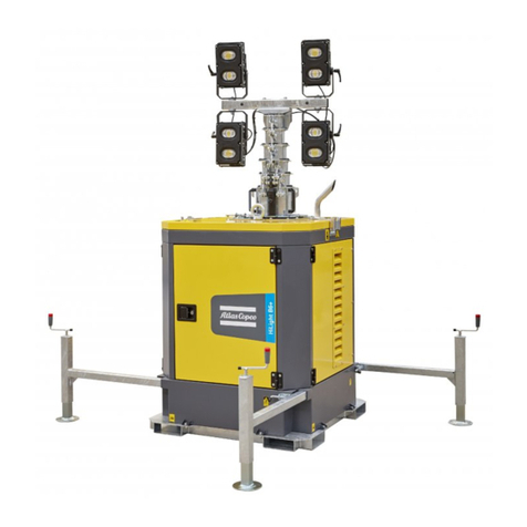
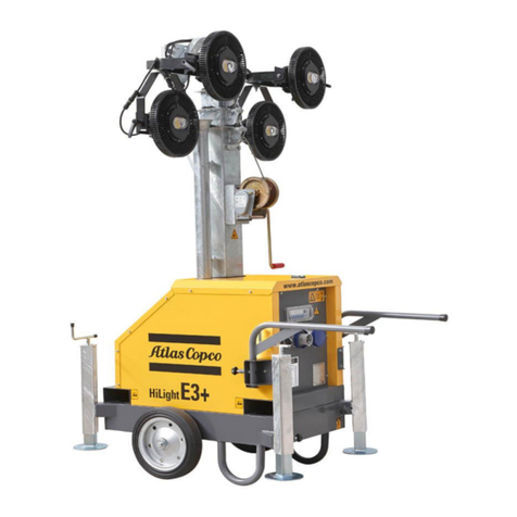
The HiLight V3+, HiLight V2+ and HiLight P2+ are portable light-towers. They have LED (Light Emitting Diode) lamps that can illuminate an average area of 2000m2.
HiLight V3+ and HiLight V2+
The HiLight V3+ and HiLight V2+ consist of the following parts:
HiLight V3+ HiLight V2+
H
HB
FB
H
HB
FB
B Beam
EEngine
FFrame
FT Fuel Tank
FB Foot Brake
HB Hand Brake
LLamp
MMast
SH Steering Handle
U Undercarriage
WWinch

- 10 -
Engine
The engine is coupled to a generator, which energizes
the LED lamps. The engine operates on petrol.
LED lamp
The HiLight V3+ lamp configuration has 4 bulbs of
120 W. The bulbs have an average life of 50,000
operational hours.
The HiLight V2+ has a 320W balloon LED lamp. It is
a non-inflatable balloon LED lamp. The lamp
illuminates an area in all directions (360° area).
HiLight V3+
HiLight V2+
Safety devices
The circuit breakers are safety devices that protect the
unit from over voltage.
Frame
The frame is a support for the mast, the generator, the
engine and the towing equipment.
Lifting Beam
The lifting hook is accessible at the top of the unit.
Data plate
The data plate in on the Base frame of the light tower.
HiLight P2+
The HiLight P2+ is a light-weight and flexible light
tower. Itcan be lifted and moved by the operator.
HiLight P2+
LAMP 1
LAMP 3
LAMP 2
LAMP 4
LAMP
CR Connecting rod
LLamp
LS Locking screw
MMast
SR Support ring
SL Support leg
SF Support foot
WWinch
LS
CR
SR
SL
SF

- 11 -
Power plug
The HiLight P2+ is a “Plug-and-light” light tower. It
must be energized by a local power source.
LED lamp
The HiLight P2+ has a 320W balloon LED lamp. It is
a non-inflatable balloon LED lamp. The lamp
illuminates an area in all directions (360° area).
HiLight P2+
LAMP

- 12 -
MARKINGS AND INFORMATION LABELS
Check oil level in engine
Check coolant level
Check petrol in the fueltank
Read the instruction manual
before filling oil
Dangerous outlet gases.
Danger, hot surface.
Use petrol fuel only.
Manual.
Read the instruction manual
before working on the battery.
coolant drain
Engine oil drain
Drain condensate daily from
vessel
Rotation direction.
Service point.
Lifting permitted.
Read the instruction manual
before lifting.
Start button
Key switch

- 13 -
PRODUCT DRAWINGS
GENERAL ARRANGEMENT DRAWINGS
HiLight V3+
+
+
+

- 14 -
HiLight V2+
+
+
+

- 15 -
HiLight P2+
+

- 16 -
CIRCUIT DIAGRAMS
COMPREHENSIVE WIRING SCHEMATIC DIAGRAM FOR LAMP CIRCUIT- 9829 3800 74

- 17 -
GENERATOR-CAPACITOR EXCITATION SCHEMATIC DIAGRAM
Reference Description
1Rotor
2 Stator
3 Excitation coils
4 Capacitor
5 Generator/terminal block
6 Control box lights
Wire Colours
B Black
Br Brown
Cl Clear
G Green
Gr Grey
LBlue
LL Light Blue
Or Orange
PPink
Pr Purple
RRed
Sh Shield
TTan
V Violet
W White
Y Yellow

- 18 -
TRAILER WIRING DIAGRAM- 1094 2932 00
Reference Description
a Right stop, turn, and tail lights
b Left stop, turn, and tail lights
c Side light, amber
d Side light, red
e License plate light
Wire Colours
G Green Right stop and turn lights
Y Yellow Left stop and turn lights
Br Brown License plate, tail, and side
lights
W White Ground
RRed

- 19 -
COMPREHENSIVE WIRING SCHEMATIC DIAGRAM FOR ENGINE CIRCUIT- 9829 3800 78

- 20 -
DEPLOYMENT AND OPERATION
SELECTING A LOCATION
• Make sure that the speed of the wind at the location does not exceed 50km/hr.
• Put the light tower at the same level or at a higher level than the location to
be illuminated. This gives the best light coverage.
• Make sure that the location is clean and level with the ground. This will
decrease risk of injury to personnel, and risk of the light tower moving or
falling.
•Make sure that the location is easy to access.
• The light tower mast can be raised to 24.5ft (7.5m). Make sure that the area
above the light tower is clear.
LIFTING
Lifting HiLight V3+ and HiLight V2+
• The lifting eye (LE) for the unit is above the engine.
• Use lifting and loading equipment, e.g. slings, hooks, chains, ramps, etc. of
the correct rating. The gross vehicle weight rating of the light tower is given
on its identification tag.
Lifting HiLight P2+
• Remove the Locking screw (LS) and bring the locking ring (SR) to the lowest
position. Do not re-fit the locking screw (LS).
• The Support legs (SL) are hinged to the connecting rod (CR) and the base of
the mast (M). The connecting rod (CR) in hinged to the locking ring (SR).
Fold the support legs (SL) up such that they touch the light tower mast (M).
Before using the HiLight V2+ or HiLight V3+ or HiLight P2+,
read the instruction manual carefully. Obey all instructions given
in the manual.
This manual suits for next models
2
Table of contents
Other Atlas Copco Lighting Equipment manuals

Atlas Copco
Atlas Copco HiLight H5+ Hd ESF User manual

Atlas Copco
Atlas Copco HiLight B6+ Kd ESF Operating instructions

Atlas Copco
Atlas Copco HiLight E2+ESF User manual

Atlas Copco
Atlas Copco Stacklight ESL-04 User manual

Atlas Copco
Atlas Copco QLT H40 User manual

Atlas Copco
Atlas Copco HiLight H6+ Kd ESF User manual
Popular Lighting Equipment manuals by other brands

Tamlite
Tamlite STADIA XL Installation & operating instructions

LIGMAN
LIGMAN ALD-30282 installation manual

goccia
goccia I-LUX 5501 quick start guide

Gemmy
Gemmy AIRBLOW INFLATABLE 221215 quick start guide

Zodiac Pool Systems
Zodiac Pool Systems Nature2 Pro A Plus Installation and operating manual

Sealite
Sealite AL-01 Installation & service manual