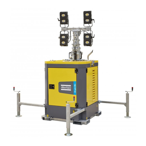
Atlas Copco HiLight E2+ESF User manual

User and maintenance manual for light towers
Gebruikers- en onderhoudshandboek voor verlichtingstorens
Manuel de l'utilisateur et de maintenance pour tours d’éclairage
Benutzer- und Wartungshandbuch für Beleuchtungstürme
Manual de uso y mantenimiento para torres de iluminación
Användar- och underhållshandbok för ljustorn
Bruger- og vedligeholdelsesvejledning til lystårne
Käyttö- ja huolto-ohjekirja valotornit
Apšvietimo bokštųnaudojimo ir priežiūros instrukcija
English - Nederlands - Français - Deutsch - Español - Svenska - Dansk - Suomi
-
Lietuviųk.
HiLight E2 & E3+ ESF
00_00_HiLight E2–E3+_9L.book Page 1 Friday, October 12, 2018 11:34 AM
Instruction Manual

- 7 -
Contents
1 Safety precautions.........................9
1.1 Introduction........................................9
1.2 General safety precautions .............10
1.3 Safety during transport and
installation........................................11
1.4 Safety during use and
operation ..........................................12
1.5 Safety during maintenance
and repair..........................................13
1.6 Tool applications safety ..................14
2 Main parts ......................................15
2.1 General description .........................15
2.2 Markings ...........................................16
2.3 Mechanical features.........................17
2.3.1 Bodywork..........................................17
2.3.2 Control panel ....................................17
2.3.3 Data plate and serial number..........17
2.3.4 Mast and floodlights ........................17
2.4 Electrical features ............................17
2.4.1 Control and indicator panel
for HiLight E2/E3+ MOD 01-02-
06-07-10-11-12 ..................................17
2.4.2 Control and indicator panel
for HiLight E2/E3+ MOD 03-04-
05-08-09-13-14 ..................................18
2.5 Available models..............................19
3 Installation and
connection......................................20
3.1 Lifting ................................................20
3.2 Positioning and transport ...............20
3.2.1 Positioning for operation.................20
3.2.2 Positioning for transport..................22
3.2.3 On-site transport ..............................23
3.2.4 Transportation and
positioning of the light tower
onto vehicles.....................................24
3.3 Installation........................................24
4 Operating instructions................26
4.1 Before starting..................................26
4.2 Operating the light tower ...............26
4.2.1 Positioning the floodlights ..............26
4.2.2 Extending/lowering the mast ..........27
4.2.3 Switching on/off the
floodlights.........................................28
5 Periodic maintenance..................29
5.1 Maintenance schedule.....................29
5.1.1 Precautions .......................................30
5.1.2 Use of maintenance schedule .........30
5.1.3 Ordering spare parts ........................30
5.1.4 Replacing the lamps.........................30
6 Checks and trouble
shooting ..........................................31
7 Options available for
HiLight E2 and E3+
units..................................................31
7.1 Overview of the mechanical
options ..............................................31
7.2 Overview of the electrical
options ..............................................31
7.3 Description of the electrical
options ..............................................31
7.3.1 Photocell ...........................................31
Congratulations on the purchase of your HiLight on-site light tower. It is a solid, safe and reliable machine, built according to the latest technology. Follow the
instructions in this booklet and we guarantee you years of trouble free operation. Please read the following instructions carefully before starting to use your machine.
While every effort has been made to ensure that the information in this manual is correct, Atlas Copco does not assume responsibility for possible errors. Atlas Copco
reserves the right to make changes without prior notice.
00_00_HiLight E2–E3+_9L.book Page 7 Friday, October 12, 2018 11:34 AM

- 8 -
8 Storage of the light tower.........33
8.1 Storage .............................................33
8.2 Preparing for operation after
storage ..............................................33
9 Disposal...........................................34
9.1 General..............................................34
9.2 Disposal of materials .......................34
10 Technical specifications .............35
10.1 Technical data of the HiLight
E2 light tower...................................35
10.2 Technical data of the HiLight
E3+ light tower.................................37
10.3 Critical bolt connections .................39
10.4 Dimension drawing (based on
MOD 4 configuration) ......................40
10.5 Conversion list of SI units into
British units ......................................42
10.6 Data plate .........................................42
00_00_HiLight E2–E3+_9L.book Page 8 Friday, October 12, 2018 11:34 AM

- 9 -
1 Safety precautions
To be read attentively and acted accordingly before towing, lifting, operating, performing maintenance or repairing the light tower.
1.1 Introduction
The policy of Atlas Copco is to provide the users of their
equipment with safe, reliable and efficient products.
Factors taken into account are among others:
- the intended and predictable future use of the
products, and the environments in which they are
expected to operate,
- applicable rules, codes and regulations,
- the expected useful product life, assuming proper
service and maintenance,
- providing the manual with up-to-date information.
Before handling any product, take time to read the
relevant instruction manual. Besides giving detailed
operating instructions, it also gives specific information
about safety, preventive maintenance, etc.
Keep the manual always at the unit location, easy
accessible to the operating personnel.
See also the safety precautions, which are separately sent
along or are mentioned on the equipment or parts of the
unit.
These safety precautions are general and some
statements will therefore not always apply to a particular
unit.
Only people that have the right skills should be allowed
to operate, adjust, perform maintenance or repair on
Atlas Copco equipment. It is the responsibility of
management to appoint operators with the appropriate
training and skill for each category of job.
Skill level 1: Operator
An operator is trained in all aspects of operating the unit
with the push-buttons, and is trained to know the safety
aspects.
Skill level 2: Mechanical technician
A mechanical technician is trained to operate the unit the
same as the operator. In addition, the mechanical
technician is also trained to perform maintenance and
repair, as described in the instruction manual, and is
allowed to change settings of the control and safety
system. A mechanical technician does not work on live
electrical components.
Skill level 3: Electrical technician
An electrical technician is trained and has the same
qualifications as both the operator and the mechanical
technician. In addition, the electrical technician may
carry out electrical repairs within the various enclosures
of the unit. This includes work on live electrical
components.
Skill level 4: Specialist from the manufacturer
This is a skilled specialist sent by the manufacturer or its
agent to perform complex repairs or modifications to the
equipment.
In general it is recommended that not more than two
people operate the unit, more operators could lead to
unsafe operating conditions. Take necessary steps to
keep unauthorized persons away from the unit and
eliminate all possible sources of danger at the unit.
When handling, operating, overhauling and/or
performing maintenance or repair on Atlas Copco
equipment, the mechanics are expected to use safe
engineering practices and to observe all relevant local
safety requirements and ordinances. The following list is
a reminder of special safety directives and precautions
mainly applicable to Atlas Copco equipment.
Neglecting the safety precautions may endanger people
as well as environment and machinery:
- endanger people due to electrical, mechanical or
chemical influences,
- endanger the environment due to leakage of oil,
solvents or other substances,
- endanger the machinery due to function failures.
All responsibility for any damage or injury resulting
from neglecting these precautions or by non-observance
of ordinary caution and due care required in handling,
operating, maintenance or repair, also if not expressly
mentioned in this instruction manual, is disclaimed by
Atlas Copco.
00_00_HiLight E2–E3+_9L.book Page 9 Friday, October 12, 2018 11:34 AM

- 10 -
The manufacturer does not accept any liability for any
damage arising from the use of non-original parts and for
modifications, additions or conversions made without
the manufacturer’s approval in writing.
If any statement in this manual does not comply with
local legislation, the stricter of the two shall be applied.
Statements in these safety precautions should not be
interpreted as suggestions, recommendations or
inducements that it should be used in violation of any
applicable laws or regulations.
1.2 General safety precautions
1. The owner is responsible for maintaining the unit
in a safe operating condition. Unit parts and
accessories must be replaced if missing or
unsuitable for safe operation.
2. The supervisor, or the responsible person, shall at
all times make sure that all instructions regarding
machinery and equipment operation and
maintenance are strictly followed and that the
machines with all accessories and safety devices,
as well as the consuming devices, are in good
repair, free of abnormal wear or abuse, and are not
tampered with.
3. Whenever there is an indication or any suspicion
that an internal part of a machine is overheated,
the machine shall be stopped but no inspection
covers shall be opened before sufficient cooling
time has elapsed; this to avoid the risk of
spontaneous ignition of oil vapour when air is
admitted.
4. The machinery and equipment shall be kept clean,
i.e. as free as possible from oil, dust or other
deposits.
5. All regulating and safety devices shall be
maintained with due care to ensure that they
function properly. They may not be put out of
action.
6. Safety devices shall be tested as described in the
maintenance schedule of the instruction manual to
determine that they are in good operating
condition.
7. Mind the markings and information labels on the
unit.
8. In the event the safety labels are damaged or
destroyed, they must be replaced to ensure
operator safety.
9. Keep the work area neat. Lack of order will
increase the risk of accidents.
10. When working on the unit, wear safety clothing.
Depending on the kind of activities these are:
safety glasses, ear protection, safety helmet
(including visor), safety gloves, protective
clothing, safety shoes. Do not wear the hair long
and loose (protect long hair with a hairnet), or
wear loose clothing or jewellery.
11. Take precautions against fire. Keep a fire-
extinguisher in the vicinity.
12. On-site light towers (with earthing pin):
Earth the light tower as well as the load properly.
13. The power source for the light towers HiLight E3+
and HiLight E2 must be protected with an Earth
Leackage Relay to avoid direct and indirect
contacts.
00_00_HiLight E2–E3+_9L.book Page 10 Friday, October 12, 2018 11:34 AM

- 11 -
1.3 Safety during transport and
installation
To lift a unit, all loose or pivoting parts, e.g. doors and
tow bar, shall first be securely fastened.
Do not attach cables, chains or ropes directly to the
lifting eye; apply a crane hook or lifting shackle meeting
local safety regulations. Never allow sharp bends in
lifting cables, chains or ropes.
Helicopter lifting is not allowed.
Lifting acceleration and deceleration shall be kept within
safe limits.
1. If a unit is to be backed up by a towing vehicle,
disengage the overrun brake mechanism (if it is
not an automatic mechanism).
2. In case of transporting a non-trailer unit on a
truck, fasten it to the truck by attaching straps via
fork lift holes, via the holes in the frame at the
front and back or via the lifting beam. To prevent
damage, never put straps on the roof surface of the
unit.
3. To lift heavy parts, a hoist of ample capacity,
tested and approved according to local safety
regulations, shall be used.
4. Lifting hooks, eyes, shackles, etc., shall never be
bent and shall only have stress in line with their
design load axis. The capacity of a lifting device
diminishes when the lifting force is applied at an
angle to its load axis.
5. For maximum safety and efficiency of the lifting
apparatus all lifting members shall be applied as
near to perpendicular as possible. If required, a
lifting beam shall be applied between hoist and
load.
6. Never leave a load hanging on a hoist.
7. A hoist has to be installed in such a way that the
object will be lifted perpendicular. If that is not
possible, the necessary precautions must be taken
to prevent load-swinging, e.g. by using two hoists,
each at approximately the same angle not
exceeding 30° from the vertical.
8. Locate the unit at least 1 meter away from walls.
9. Light towers shall be stalled on an even, solid
floor, in a clean location with sufficient
ventilation. If the floor is not level or can vary in
inclination, consult Atlas Copco.
10. The electrical connections shall correspond to
local codes. The machines shall be earthed and
protected against short circuits by fuses or circuit
breakers.
11. Never connect the light tower outlets to an
installation which is also connected to a public
mains.
12. Before connecting a load, switch off the
corresponding circuit breaker, and check whether
frequency, voltage, current and power factor
comply with the ratings of the light tower.
13. Before transportation of the unit, switch off all the
circuit breakers.
00_00_HiLight E2–E3+_9L.book Page 11 Friday, October 12, 2018 11:34 AM

- 12 -
1.4 Safety during use and
operation
1. Periodically carry out maintenance works
according to the maintenance schedule.
2. Stationary housing guards are provided on all
rotating or reciprocating parts not otherwise
protected and which may be hazardous to
personnel. Machinery shall never be put into
operation, when such guards have been removed,
before the guards are securely reinstalled.
3. When the sound pressure level, at any point where
personnel normally has to attend, is:
- below 70 dB(A): no action needs to be taken,
- above 70 dB(A): noise-protective devices should
be provided for people continuously being
present in the room,
- below 85 dB(A): no action needs to be taken for
occasional visitors staying a limited time only,
- above 85 dB(A): room to be classified as a noise-
hazardous area and an obvious warning shall be
placed permanently at each entrance to alert
people entering the room, for even relatively
short times, about the need to wear ear
protectors,
- above 95 dB(A): the warning(s) at the
entrance(s) shall be completed with the
recommendation that also occasional visitors
shall wear ear protectors,
- above 105 dB(A): special ear protectors that are
adequate for this noise level and the spectral
composition of the noise shall be provided and a
special warning to that effect shall be placed at
each entrance.
4. Never operate the unit in surroundings where
there is a possibility of taking in flammable or
toxic fumes.
5. If the working process produces fumes, dust or
vibration hazards, etc., take the necessary steps to
eliminate the risk of personnel injury.
6. When using compressed air or inert gas to clean
down equipment, do so with caution and use the
appropriate protection, at least safety glasses, for
the operator as well as for any bystander. Do not
apply compressed air or inert gas to your skin or
direct an air or gas stream at people. Never use it
to clean dirt from your clothes.
7. When washing parts in or with a cleaning solvent,
provide the required ventilation and use
appropriate protection such as a breathing filter,
safety glasses, rubber apron and gloves, etc.
8. Safety shoes should be compulsory in any
workshop and if there is a risk, however small, of
falling objects, wearing of a safety helmet should
be included.
9. If there is a risk of inhaling hazardous gases,
fumes or dust, the respiratory organs must be
protected and depending on the nature of the
hazard, so must the eyes and skin.
10. Remember that where there is visible dust, the
finer, invisible particles will almost certainly be
present too; but the fact that no dust can be seen is
not a reliable indication that dangerous, invisible
dust is not present in the air.
11. Never operate the light tower in excess of its limits
as indicated in the technical specifications and
avoid long no-load sequences.
12. Never operate the light tower in a humid
atmosphere. Excessive moisture causes
worsening of the light tower insulation.
13. Do not open electrical cabinets, cubicles or other
equipment while voltage is supplied. If such
cannot be avoided, e.g. for measurements, tests or
adjustments, have the action carried out by a
qualified electrician only, with appropriate tools,
and ascertain that the required bodily protection
against electrical hazards is applied.
14. Never touch the power terminals during operation
of the machine.
15. Whenever an abnormal condition arises, e.g.
excessive vibration, noise, odour, etc., switch the
circuit breakers to OFF. Correct the faulty
condition before restarting.
16. Check the electric cables regularly. Damaged
cables and insufficient tightening of connections
may cause electric shocks. Whenever damaged
wires or dangerous conditions are observed,
switch the circuit breakers to OFF and stop the
unit. Replace the damaged wires or correct the
dangerous condition before restarting. Make sure
that all electric connections are securely
tightened.
00_00_HiLight E2–E3+_9L.book Page 12 Friday, October 12, 2018 11:34 AM
- 13 -
17. Avoid overloading the light tower. The light tower
is provided with circuit breakers for overload
protection. When a breaker has tripped, reduce the
concerned load before restarting.
18. Never remove the cover of the output terminals
during operation. Before connecting or
disconnecting wires, switch off the load and the
circuit breakers, stop the machine and make sure
that the machine cannot be started inadvertently or
there is any residual voltage on the power circuit.
19. When operating the light tower in Remote or Auto
mode, observe all relevant local legislation.
20. When deploying the light tower mast, keep in
mind following safety precautions:
- Do not deploy the mast unless the machine is
standing on an even surface and the stabilizers
have been fully adjusted.
- Do not deploy the mast in the vicinity of
overhead power cables: DANGER OF
ELECTROCUTION.
- Do not raise the mast with the lights in transport
position.
- Make sure that nobody is standing too close to
the light tower when the mast is being deployed.
- Do not deploy the mast if the wind is stronger
than 80 Km/h, if the light tower is in operation
position (lights not in line with the wheels).
1.5 Safety during maintenance
and repair
Maintenance, overhaul and repair work shall only be
carried out by adequately trained personnel; if required,
under supervision of someone qualified for the job.
1. Use only the correct tools for maintenance and
repair work, and only tools which are in good
condition.
2. Parts shall only be replaced by genuine Atlas
Copco replacement parts.
3. All maintenance work, other than routine
attention, shall only be undertaken when the unit
is stopped. Steps shall be taken to prevent
inadvertent starting. In addition, a warning sign
bearing a legend such as “work in progress; do not
start” shall be attached to the starting equipment.
On electrically driven units the main switch shall
be locked in open position and the fuses shall be
taken out. A warning sign bearing a legend such as
“work in progress; do not supply voltage” shall be
attached to the fuse box or main switch.
4. Make sure that no tools, loose parts or rags are left
in or on the machine.
5. Never use flammable solvents for cleaning (fire-
risk).
6. Take safety precautions against toxic vapours of
cleaning liquids.
7. Never use machine parts as a climbing aid.
8. Observe scrupulous cleanliness during
maintenance and repair. Keep away dirt, cover the
parts and exposed openings with a clean cloth,
paper or tape.
9. Use only lubricating oils and greases
recommended or approved by Atlas Copco or the
machine manufacturer. Ascertain that the selected
lubricants comply with all applicable safety
regulations, especially with regard to explosion or
fire-risk and the possibility of decomposition or
generation of hazardous gases.
10. When performing any operation involving heat,
flames or sparks on a machine, the surrounding
components shall first be screened with non-
flammable material.
11. Never use a light source with open flame for
inspecting the interior of a machine.
12. When repair has been completed, the machine
shall be barred over at least one revolution for
reciprocating machines, several revolutions for
rotary ones to ensure that there is no mechanical
interference within the machine or driver.
13. Maintenance and repair work should be recorded
in an operator’s logbook for all machinery.
Frequency and nature of repairs can reveal unsafe
conditions.
00_00_HiLight E2–E3+_9L.book Page 13 Friday, October 12, 2018 11:34 AM

- 14 -
14. When hot parts have to be handled, e.g. shrink
fitting, special heat-resistant gloves shall be used
and, if required, other body protection shall be
applied.
15. Make sure that oil, solvents and other substances
likely to pollute the environment are properly
disposed of.
16. Before clearing the light tower for use after
maintenance or overhaul, submit it to a test run,
check that the AC power performance is correct
and that the control and shutdown devices
function correctly.
1.6 Tool applications safety
Apply the proper tool for each job. With the knowledge
of correct tool use and knowing the limitations of tools,
along with some common sense, many accidents can be
prevented.
Special service tools are available for specific jobs and
should be used when recommended. The use of these
tools will save time and prevent damage to parts.
00_00_HiLight E2–E3+_9L.book Page 14 Friday, October 12, 2018 11:34 AM

- 15 -
2 Main parts
2.1 General description
The HiLight E2 and E3+ light towers provide 4 floodlights with different installed power depending on the configuration of the unit. They are built for running at sites
where electricity is available from mains or generator. There are 14 HiLight E2 and E3+ models available (MOD 01–14), of which each offering a slightly different
configuration.
DP Data plate
FL Floodlights
FS Forklift slots
H Handles (for transport on site)
LE Lifting eye
LH Levelling handle, to adjust the height of the
supporting foot
LPS Locking pin stabilizer
MMast
P Photocell (option)
ST Stabilizer and supporting foot
U Undercarriage
WWinch
DP
FL
FS
H
LE
LH
LPS
M
P
ST
W
U
00_00_HiLight E2–E3+_9L.book Page 15 Friday, October 12, 2018 11:34 AM

- 16 -
2.2 Markings
Markings provide instructions and information. They
also warn of hazards. For convenience and safety,
keep all markings in legible condition, replacing them
when damaged or missing. Replacement markings are
available from the factory.
A brief description of all markings provided on the
light tower is given hereafter. The precise location of
all markings can be found in the parts manual of this
light tower.
Indicates that an electric voltage,
dangerous to life, is present. Never
touch the electric terminals during
operation.
Indicates that the mast should not be
extended near electric wires.
Indicates the locking pin of the
stabilizers.
Indicates the forklift slots.
Indicates the lifting point of the light
tower.
Indicates that the unit may
start automatically and
that the instruction book
has to be consulted prior
to use.
Indicates the earthing connections on
the light tower.
Indicates the danger of touching
rotating parts of the unit.
Indicates the different
service packs, liquids and
critical parts. These parts
can be ordered to the
factory.
HiLight E3+
HiLight E2
Cubicle
Description Order Nr
CIRCUIT BREAKER 2P 32A 1636007756
CIRCUIT BREAKER 1P 6A 1636007754
PLUG CEE 230V 32A 2P+PE 1636007757
SOCKET CEE 230V 32A 2P+PE 1636007758
CIRCUIT BREAKER 2P 10A 1636007781
PLUG 230V 10A 2P+PE CABLE 1636007773
PLUG 110V 32A 2P+PE 1636009199
SOCKET 110V 32A 2P+PE 1636009198
PHOTOCELL SWICHT 1636007770
TIMER RELAY 1636009203
Frame & Mounts
Description Order Nr
WHEEL 1636007736
HANDLES 1636007763
PVC HANDLE 1636007765
Light Tower
Description Order Nr
ADJUSTMENT PLATE 36X30 1636007883
ADJUSTMENT PLATE 50X30 1636001777
ADJUSTMENT PLATE 60X30 1636001914
ROPE 6 MM 1636007846
ROPE 5 MM 1636007744
WINCH 1636007745
FLOODLIGHT - MH 1636007750
BULB 250W 1636007751
BULB 400W 1636007752
BALLAST GEAR 400W 1636007778
BALLAST GEAR 250W 1636007885
FLOODLIGHT - LED 1636009017
LENS 1636302659
LED 1636302660
LED DRIVER 1636302658
ELECTRICAL CABLE 1636007747
RUBBER PROFILE 1636007740
1636008335 www.atlascopco.com
00_00_HiLight E2–E3+_9L.book Page 16 Friday, October 12, 2018 11:34 AM

- 17 -
2.3 Mechanical features
The mechanical features described in this chapter are
standard provided on this light tower. For all optional
mechanical features, see chapter “Overview of the
mechanical options” on page 31.
2.3.1 Bodywork
The HiLight E2 and E3+ can be lifted by using the
lifting eye integrated in the mast. Galvanized forklift
pockets are provided in the frame, to allow lifting of
the unit from both sides.
2.3.2 Control panel
The control panel grouping fuses, automatic switches,
sockets, etc., is accessible by removing the panel at
the front.
2.3.3 Data plate and serial number
The light tower is furnished with a data plate showing
the product code and serial number (see chapter “Data
plate” on page 42). It is located on the panel at the
front.
2.3.4 Mast and floodlights
The 100% galvanized light tower mast consists of 6
mast sections and can be extended up to 6.9 metres. It
is manually operated.
The light tower provides several configurations of
floodlights and different installed power. Each lamp
can be separately positioned and inclined.
2.4 Electrical features
The electrical features described in this chapter are
standard provided on this light tower. For all optional
electrical features, see chapter “Overview of the
electrical options” on page 31.
2.4.1 Control and indicator panel for
HiLight E2/E3+ MOD 01-02-06-
07-10-11-12
Overview of the control panel
To operate the light tower a control panel is installed.
P7........Photocell (optional)
P8........Timer (optional)
Q1 .......General circuit breaker
Interrupts the power supply when a short-
circuit occurs at the load side, or when the
overcurrent protection is activated. It allows
to isolate the machine.
Q2-5....Circuit breakers for lamps
The control panel provides 4 circuit breakers
for the lamps (one for each lamp).
S20......REMOTE/ON/OFF switch (optional)
The S20 switch only applies in models with
Timer and Photocell option installed.
Following positions can be selected:
MAN.: ON, for manual switch on
O: OFF, to disconnect
AUTO.: REMOTE START, for Auto
Photocell and weekly timer start
option. Connection in series of
both devices.
TIM.: REMOTE START, for weekly
timer start option.
PHOTO.: REMOTE START, for Auto
Photocell start option.
X1 .......Inlet plug for connection to the mains
(Check models table for more details)
X2 .......Outlet socket (Check models table for
more details)
S20 X1 X2
P7
P8
Q1
Q2-5
00_00_HiLight E2–E3+_9L.book Page 17 Friday, October 12, 2018 11:34 AM

- 18 -
2.4.2 Control and indicator panel for
HiLight E2/E3+ MOD 03-04-05-
08-09-13-14
Overview of the control panel
To operate the light tower a control panel is installed.
P7........ Photocell (optional)
P8........ Timer (optional)
Q1.......General circuit breaker
Interrupts the power supply when a short-
circuit occurs at the load side, or when the
overcurrent protection is activated. It allows
to isolate the machine.
Q2-5....Circuit breakers for lamps
The control panel provides 4 circuit breakers
for the lamps (one for each lamp).
S20 .....REMOTE/ON/OFF switch (optional)
The S20 switch only applies in models with
Timer and Photocell option installed.
Following positions can be selected:
MAN.: ON, for manual switch on
O: OFF, to disconnect
AUTO.: REMOTE START, for Auto
Photocell and weekly timer start
option. Connection in series of
both devices.
TIM.: REMOTE START, for weekly
timer start option.
PHOTO.: REMOTE START, for Auto
Photocell start option.
X1 .......Inlet plug for connection to the mains
(Check models table for more details)
S20
P7
P8
Q1
Q2-5
X1
00_00_HiLight E2–E3+_9L.book Page 18 Friday, October 12, 2018 11:34 AM

- 19 -
2.5 Available models
List of abbreviations:
– TMR = Timer/Photocell option
– SKT = IN socket only
– 250 = 250W light output
– 110 = 110VAC power input
Model Name Floodlight Socket IN Socket OUT Timer and
Photocell Power input
MOD01 HiLight E2 4x Halide 400W CEE 32A, 2PH+PE, IP67 CEE 32A, 2PH+PE, IP67 NO 230V
MOD02 HiLight E2 TMR 4x Halide 400W CEE 32A, 2PH+PE, IP67 CEE 32A, 2PH+PE, IP67 YES 230V
MOD03 HiLight E2 SKT 4x Halide 400W Cable + SHUKO plug, 10A, 2PH+PE NO NO 230V
MOD04 HiLight E2 SKT TMR 4x Halide 400W Cable + SHUKO plug, 10A, 2PH+PE NO YES 230V
MOD05 HiLight E2 250 SKT TMR 4x Halide 250W Cable + SHUKO plug, 10A, 2PH+PE NO YES 230V
MOD06 HiLight E3+ 4x LED 165W CEE 32A, 2PH+PE, IP67 CEE 32A, 2PH+PE, IP67 NO 230V
MOD07 HiLight E3+ TMR 4x LED 165W CEE 32A, 2PH+PE, IP67 CEE 32A, 2PH+PE, IP67 YES 230V
MOD08 HiLight E3+ SKT 4x LED 165W Cable + SHUKO plug, 10A, 2PH+PE NO NO 230V
MOD09 HiLight E3+ SKT TMR 4x LED 165W Cable + SHUKO plug, 10A, 2PH+PE NO YES 230V
MOD010 HiLight E3+ 110 4x LED 165W CEE 32A, 110V, 2PH+PE, IP67 CEE 32A, 110V, 2PH+PE, IP67 NO 110V
MOD011 HiLight E3+ TMR 110 4x LED 165W CEE 32A, 110V, 2PH+PE, IP67 CEE 32A, 110V, 2PH+PE, IP67 YES 110V
MOD012 HiLight E3+ 120 4x LED 165W NEMA 20A, 2PH+PE, IP44 NEMA 20A, 2PH+PE, IP44 NO 120V
MOD013 HiLight E3+ 120 SKT 4x LED 165W NEMA 20A, 2PH+PE, IP44 NO NO 120V
MOD014 HiLight E3+ 120 SKT D 4x LED 165W Cable + NEMA plug, 15A, 2PH+PE NO NO 120V
00_00_HiLight E2–E3+_9L.book Page 19 Friday, October 12, 2018 11:34 AM

- 20 -
3 Installation and
connection
3.1 Lifting
The lifting eye (1), to lift the light tower by means of
a hoist, is integrated in the mast and easily accessible
from the outside.
While lifting, the light tower will be tilted towards the
mast to avoid damage to the floodlights.
To be able to lift the light tower by means of a forklift,
forklift slots (2) are provided in the frame. 3.2 Positioning and transport
3.2.1 Positioning for operation
Follow the steps below to position the light tower:
1. Place the light tower on a horizontal, even and
solid floor.
2. Make sure that the mast is down.
3. To extend the stabilizers; release the locking pin
of each stabilizer (1) by lifting it up and pull the
supporting foot (2) at the maximum extension of
the stabilizer (3).
Lifting acceleration and deceleration
must be kept within safe limits (max.
2 g).
Helicopter lifting is not allowed.
1
To lift the HiLight E2 and E3+ by
using the lifting eye, the flood lights
should be in operation position. To
lift the light tower by means of a fork
lift, the flood lights can be both in
operation or transport position. See
also chapter “Positioning and
transport”.
2
2
The operator is expected to apply all
relevant safety precautions,
including those mentioned on page
10 to page 14 of this booklet.
1
2
2
2
2
3
3
3
3
00_00_HiLight E2–E3+_9L.book Page 20 Friday, October 12, 2018 11:34 AM

- 21 -
4. Once the stabilizers (3) have been extended,
release the locking pin (1) to lock them in
position.
5. Turn the handle (4) at the top of the supporting
feet anticlockwise to lower them and put the light
tower in a level position.
6. Rotate the floodlight support 90º (operation
position) by loosening the 4 screws on top (6).
When the support is correctly positioned, tighten
the 4 screws again.
For more detailed installation instructions, see also
chapter “Installation” on page 24.
Adjust the height of the supporting
feet gradually in order to ensure the
stability of the unit.
4
Check the levels (5) on top of the
light tower to ensure that the unit is
in a level position.
5
6
00_00_HiLight E2–E3+_9L.book Page 21 Friday, October 12, 2018 11:34 AM

- 22 -
3.2.2 Positioning for transport
1. Make sure the mast is lowered (1).
2. Use the handle at the top of each foot (2) to retract
the 4 feet (3).
3. Retract the stabilizers (4) and ensure their locking
pins (5) following the reverse order of the
procedure described in “Positioning for
operation” on page 20.
4. Loosen the 4 screws of the floodlight support (6)
and rotate the support 90° (transport position).
Tighten the 4 screws again.
1
Adjust the height of the supporting
feet gradually in order to ensure the
stability of the unit.
5
3
3
3
44
4
4
2
2
2
2
3
1
6
00_00_HiLight E2–E3+_9L.book Page 22 Friday, October 12, 2018 11:34 AM
- 23 -
5. Once all the above actions have been completed,
the light tower is ready for transport:
3.2.3 On-site transport
The HiLight E2 and E3+ provide an undercarriage
with wheels (1) and folding handles (2) to allow easy
transport on site.
The handles can be unfolded by loosening the locking
pins (3).
Make sure that the light tower is in
transport position before carrying
out any kind of transport.
1
2
3
00_00_HiLight E2–E3+_9L.book Page 23 Friday, October 12, 2018 11:34 AM
- 24 -
3.2.4 Transportation and positioning
of the light tower onto vehicles
Due to its compact and optimized design, the
HiLight E2 and E3+ offer a great transport efficiency.
The light tower can be easily lifted and moved to
difficult areas thanks to its central lifting eye and
forklift pockets in its frame. All that is needed is a
forklift truck or a mechanical arm.
The forklift pockets and the lifting eye can also be
used to place the light tower onto trucks for road
transportation. For safe transport of the light towers
on trucks or similar vehicles:
1. Ensure that the machine is stable and secure.
2. Check that the light tower is placed perfectly
horizontally (check the levels on top of the unit).
3. To ensure stability, use the fork lift slots (1) and
lifting eye (2) to fix the light tower to the transport
vehicle.
4. Use straps or other means of anchoring, provided
that these do not affect the machine's safe
transportation and integrity.
5. It is recommended that the machine is covered by
a tarpaulin to protect it against bad weather
conditions if it is transported on an open truck.
3.3 Installation
– Place the light tower on a horizontal, even and
solid floor. Check the levels on top of the light
tower to ensure its level position.
– Leave enough space for operation, inspection and
maintenance (at least 1 meter at each side).
– Check that the inner earthing system is in
compliance with the local legislation.
– Use a cable of suitable section to connect the PE
terminal to an earth plate that can ensure an earth
resistance suited to the characteristics of the light
tower.
– Check that the cable end of the earth pin is
connected to the earth terminal.
– HiLight E2 and E3+ with IN/OUT sockets can be
connected in a row. The following cabling criteria
based on section and length are recommended:
• Maximum number of HiLight E2 with halide
floodlights in series: 4 units
• Maximum number of HiLight E3+ with LED
floodlights in series: 10 units
• For sections or distances out of the
recommendation please contact your Atlas
Copco technical service.
1
1
2
The light tower is wired for a TN-
system to IEC 364-3, i.e. one point in
the power source directly earthed -
in this case the neutral. The exposed
conductive parts of the electric
installation must be directly
connected to the functional earth.
00_00_HiLight E2–E3+_9L.book Page 24 Friday, October 12, 2018 11:34 AM

- 25 -
Installation recommendations for HiLight E2:
Power (1x HiLight E2) 1600 W
Cross section 6 mm³
Length (L1) 47.61 m
Power (2x HiLight E2) 3200 W
Cross section 6 mm³
Length (L2) 23.81 m
Power (3x HiLight E2) 4800 W
Wiring section 6 mm³
Length (L3) 15.87 m
Power (4x HiLight E2) 6400 W
Wiring section 6 mm³
Length (L4) 11.90 m
HiLight E2
01
L1
HiLight E2
01
HiLight E2
02
L2
HiLight E2
01
HiLight E2
02
HiLight E2
03
L3
HiLight E2
01
HiLight E2
02
HiLight E2
03
HiLight E2
04
L4
Supply
Supply
Supply
Supply
00_00_HiLight E2–E3+_9L.book Page 25 Friday, October 12, 2018 11:34 AM
This manual suits for next models
1
Table of contents
Other Atlas Copco Lighting Equipment manuals

Atlas Copco
Atlas Copco HiLight B6+ Kd ESF Operating instructions

Atlas Copco
Atlas Copco HiLight H6+ Kd ESF User manual

Atlas Copco
Atlas Copco HiLight H5+ Hd ESF User manual

Atlas Copco
Atlas Copco QLT H40 User manual

Atlas Copco
Atlas Copco Stacklight ESL-04 User manual

Atlas Copco
Atlas Copco HiLight V2+ User manual