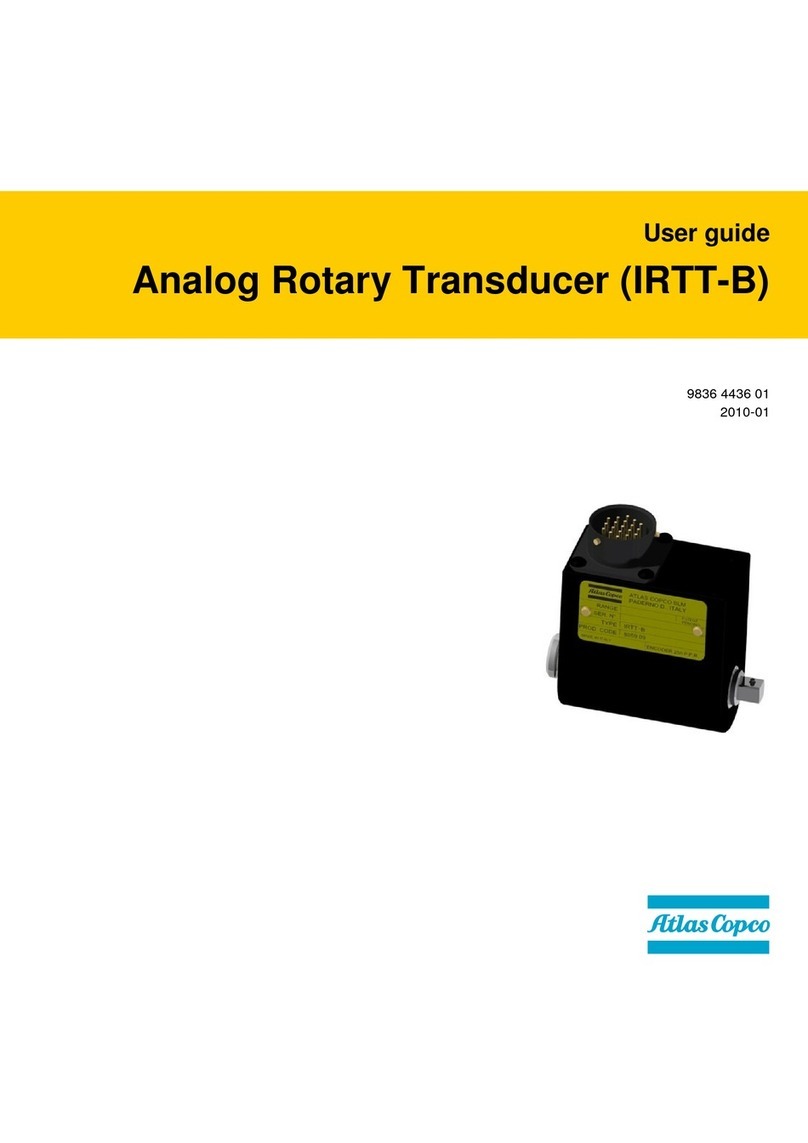
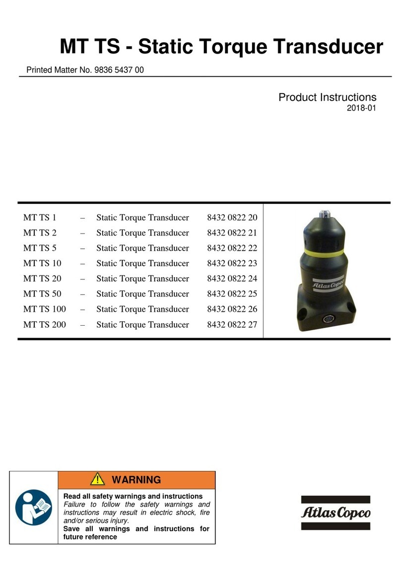
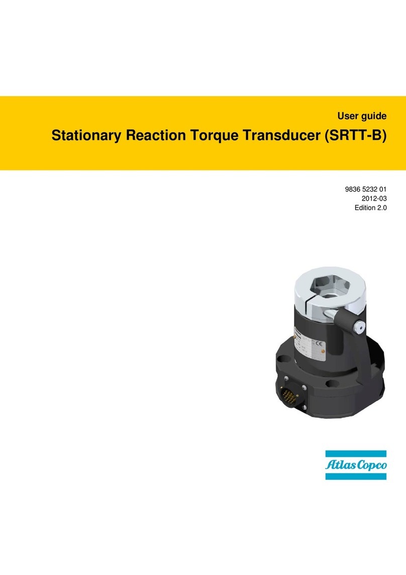
Atlas Copco IRTT-B User manual

User guide
Analog Rotary Transducer (IRTT-B)
Atlas Copco Tools and Assembly Systems
9836 4436 01
2015-01
Edition 2.8


IRTT-B User Guide
9836 4436 01 Edition 2.8 3 (8)
Safety Instructions
CAREFULLY READ THIS MANUAL PRIOR TO USING
THE PRODUCT AND SCRUPULOUSLY COMPLY WITH
THE FOLLOWING SAFETY INSTRUCTIONS.
When using electric products, basic precautions should always be
taken, including the following:
•Read all instructions before using the product.
•Do not expose the system to excessive moisture (dripping or
splashing), and do not use it near water (near a washbowl, or in
a wet basement) or other liquids.
•The product should not be subjected to continuous or excessive
shock or vibration.
•For minimum electrical interference, use the product far away
from possible sources of electrical noise (arc welding
equipment etc).
•There are no user serviceable parts inside the product. Hence,
under no circumstances should you open or resume to repair
the product. Doing so will invalidate all warranties. Refer all
service needs to your local Atlas Copco service personnel.
WARNING
Never overload more than 25% of the rated maximum
transducer capacity. This will cause the yielding of the
transducer!
To maintain the accuracy, ensure that the transducer is
regularly calibrated.
WARNING
The IRTT-B is not suitable for impact type tools
WARNING
The tool under test must be fully inserted in the
transducer as shown in the next figure:
WARNING
Use adapters suitable for the torque applied during the
test. If more than one adapter is used, consider the
maximum torque of the smallest adapter used in the
chain.
EC Declaration of conformity
Individual machinery and safety components:
We Atlas Copco BLM – Paderno Dugnano - ITALY declare under
our sole responsibility that the product to which this declaration
relates, is in conformity with the requirements of the 2011/65/CE
and EN 60950.
Information on Waste of Electrical and Electronic Equipment:
This product and its information meets the requirements of the
WEEE Directive (2002/96/EC) and successive modifications. See
the last chapter of this manual for details.
The products and their components and/or batteries that must be
treated as WEEE when at end of life are marked with a crossed
trashcan according to WEEE (2002/96/EC). See figure below:
In the European Union, this symbol indicates that products must
not be disposed of as unsorted municipal waste but must be dealt
with separately, in accordance with the WEEE Directive
(2002/96/EC).
At the end of its life, this product must be disposed of according to
local regulations.
Contact your Atlas Copco customer center to get a copy of the
WEEE manual (dismantling manual).
Collecting properly the wasted parts for consequent shipment to
recycling process, to the treatment and to the environmental
compatible dismiss contributes to avoid possible negative effects
on the environment, on health and helps the re-use and/or recycling
of the materials composing the equipment.
The abusive product dismissing by the user implicates
administrative sanctions according to the present regulation.
Name of issuer Position Signature
Massimo Usuelli Product Quality Manager
OK
Not OK
Tool not properly
inserted in the
transducer!

IRTT-B User Guide
4 (8) 9836 4436 01 Edition 2.8
GENERAL
The IRTT-B transducer provides torque measurement on a rotary
transducer, with optional angle reading.
The torque measurement is performed with a precise extensometer
bridge with special brushes to transfer the signal from the rotating
shaft to the housing; these brushes have been developed to be very
reliable and should not have the need of any maintenance through
out its life.
The angle reading is performed with a rotating magnetic sensor.
A built in memory stores identification and calibration data for
automatic reading from the measurement instrument.
TECHNICAL
•Torque measurement range: 1 ÷ 10000 Nm
•Torque static accuracy
± 0.5% of the torque applied (from 20% to 100% of the
transducer capacity)
± 1% of the torque applied (from 10% to 20% of the
transducer capacity)
•Overload capacity: 125% of rated maximum transducer
capacity
•Temperature stability of torque measurement:
0.1% of capacity/10°C
•Bridge resistance: 350 ohm
•Operation humidity: 10-75% non condensing
•Operating temperature: 5 to 40°C
The transducer comes with Atlas Copco BLM calibration
certificate.
CONNECTOR PIN OUT
TRANSDUCER BUILT IN MEMORY
The built in memory consist in a eeprom, which stores the
following data:
•Identification
•Serial Number
•Calibration (Nm)
•Full scale value (% of cal. Value)
•Sensitivity (2mV/V)
•Pulses / rev (the value written here is the number of
rising edges of the cw lead signal)
•Date of latest calibration
•Next calibration date
•Source of Calibration
TORQUE ONLY MODELS
Model Capacity (Nm) Drive Ordering No.
5-I06
5
¼” hex
8059 0942 05
5-06
5
¼” square
8059 0942 07
20-I06
20
¼” hex
8059 0942 10
20-06
20
¼” square
8059 0942 15
25-10
25
3/8” square
8059 0942 20
75-10
75
3/8” square
8059 0942 25
180-13
180
1/2” square
8059 0942 30
500-20
500
¾” square
8059 0942 35
750-25
750
1” square
8059 0942 40
1400-25 1400 1” square 8059 0942 45
3000-38
3000
1 ½” square
8059 0942 52
5000-38
5000
1 ½” square
8059 0942 56
TORQUE AND ANGLE MODELS
Model Capacity
(Nm)
Pulses per
revolution
(*)
Drive Ordering No.
1A-I06
1
256/1024
¼” hex
8059 0943 96
2A-I06
2
256/1024
¼” hex
8059 0943 01
5A-I06 5 256/1024
¼” hex 8059 0943 06
5A-06
5
256/1024
¼” square
8059 0943 08
20A-I06
20
256/1024
¼” hex
8059 0943 11
20A-06
20
256/1024
¼” square
8059 0943 16
25A-10
25
256/1024
3/8” square
8059 0943 21
75A-10
75
256/1024
3/8” square
8059 0943 26
180A-13
180
256/1024
1/2” square
8059 0943 31
500A-20
500
256/1024
¾” square
8059 0943 36
750A-25
750
256/1024
1” square
8059 0943 41
1400A-25
1400
256/1024
1” square
8059 0943 46
3000A-38
3000
384/1536
1 ½” square
8059 0943 52
5000A-38
5000
384/1536
1 ½” square
8059 0943 56
10000A-38
10000
512/2048
1 ½” square
8059 0943 60
(*): The number of pulses depends from the measuring instrument
connected to the IRTT-B. If the instrument connected to the IRTT-
B reads, for instance, only the rising edge of only the “cw lead”
signal, the number of pulses is the value written in the built in
memory of the IRTT-B (first value specified in the table above). If
the instrument reads both the rising and falling edges of both the
encoder signals (“cw lead” and “cw trail”) the number of pulses
gets multiplied by four (second value shown in the table above).
The angle resolution is given by the following formula:
Angle resolution = 360° / number of pulses
For a 20 Nm IRTT-B connected, for instance, to a STanalyser
(which reads 1024 pulses per revolution) the angle resolution
provided by the IRTT-B is ± 360°/1024 = ± 0.35°..
Pin Function
A
Excitation +
B
Excitation –
C
Signal +
D Signal –
E
–
F
Angle encoder cw trail (for versions with angle)
G
Eeprom Clock
H
Angle encoder cw lead (for versions with angle)
J
Eeprom data
K-L-
M-N
–
P
Ground (angle and eeprom)
R
+ 5V for angle reading (for versions with angle)
S
–
T
+ 8/12V eeprom power supply
U-V –

IRTT-B User Guide
9836 4436 01 Edition 2.8 5 (8)
OPERATIONS
Select the correct transducer having a torque capacity not less than
the maximum torque capacity of the tool used. Secure the tool
output spindle to the transducer input socket (hexagon shaft). Fit
the correct socket to the transducer output square drive (or bit in
bit-holder) and make sure it is secured.
Connect the transducer to the measuring instrument with the proper
cable. If you use an ACTA instrument the calibration data will be
loaded automatically and no manual entering of the value is
required.
If you use another measuring instrument the transducer shunt
calibration value and the angle pulses must be entered manually.
The shunt calibration value is marked on the transducer, the bridge
impedance is 350 Ohm and a 43,575 Ohm resistor is necessary.
Make sure to align the tool/transducer, to avoid any influence from
side forces which may affect the measurement.
If a tool is tested with a reaction bar the effective radial position of
the reaction bar point should not be less than a certain value (see
the next table and figure); not observing this requirement and
exceeding the maximum torque rating may cause a permanent
damage to the transducer.
DIMENSIONS (SAME FOR TORQUE AND TORQUE/ANGLE MODELS):
Weight (grams)
Model
Drive
A
B
C
D
E
F
G
H
J
with angle
without angle
1A-I06
hex
115,8
31
71,9
39,2
56
20,6
25,5
15,5
59
230
-
2A-I06
hex
115,8
31
71,9
39,2
56
20,6
25,5
15,5
59
230
-
5A-I06
hex
115,8
31
71,9
39,2
56
20,6
25,5
15,5
59
235
215
5A-06
square
71,5
31
71,9
9,5
56
6
7,3
15,5
59
220
-
20A-I06
hex
115,8
31
71,9
39,2
56
20,6
25,5
15,5
59
240
220
20A-06
square
71,5
31
71,9
9,5
56
6
7,3
15,5
59
240
225
25A-10
square
76,1
31
71,9
12,1
56
8
11
15,5
59
260
245
75A-10
square
76,1
31
71,9
12,1
56
8
11
15,5
59
260
245
180A-13
square
87
42
82,9
17
58
12
15,2
21
70
460
410
500A-20
square
106
52
92,9
25
66
15
23
26
80
950
890
750A-25
square
125
65
104,9
30
73
22
28
32,5
92
1370
1320
1400A-25
square
125
65
104,9
30
73
22
28
32,5
92
1420
1380
3000A-38
square
165
106
148,5
41,8
88
35,2
39,2
53
136
4550
4500
5000A-38
square
165
106
148,5
41,8
88
35,2
39,2
53
136
4420
4370
10000A-38
square
165
106
155,9
41,8
95
28,2
39,2
53
143
5500
-
WARNING
When using the IRTT-B with a 90°bent reaction bar there is a risk of large side forces, which may damage the transducer, the min. radial
position is measurement R according to the following figure. The ideal solution is to use a straight reaction bar in 90°angle to the IRTT-B.
Square Drive
Hexagon Drive

IRTT-B User Guide
6 (8) 9836 4436 01 Edition 2.8
Hex. and
square
drive size
Torque
rating
Nm
Maximum RPM Min. radial
Position (*)
R
mm
Maximum RPM
for Angle Reading
Models
Continuous Intermittent
1/4" hex.
1
5000
5000
50
2500
1/4" hex.
2
5000
11000
50
2500
1/4" hex.
5
5000
11000
50
2500
1/4" sq.
5
5000
11000
100
2500
1/4" hex.
20
5000
11000
100
2500
1/4" sq.
20
5000
11000
100
2500
3/8" sq. 25 2500 10000 50 2500
3/8" sq.
75
2500
10000
150
2500
1/2" sq.
180
2500
7600
180
2500
3/4" sq. 500 2000 5000 240 2000
1" sq.
750
1000
4400
190
1000
1" sq.
1400
1000
4400
350
1000
1 ½" sq.
3000
1000
4400
600
1000
1 ½" sq
5000
1000
4400
600
1000
1 ½” sq.
10000
1000
4400
600
1000
(*) Minimum radial position of reaction bar at max. torque, see figure on the right.
SCHEDULED MAINTENANCE
An annual calibration is required. At the time of the calibration, verify that the bearings are working well (the shaft must rotate smoothly).
TROUBLESHOOTING GUIDE
Here is a quick troubleshooting guide for the IRTT-B Transducer.
If a problem appears, before taking any action (replacing parts or contacting the customer support) be sure that the transducer is being used in the
proper way and connected to a proper and working measurement unit; improper operations can cause defects or incorrect readings even if the
transducer is good.
Problem Cause Solution
Shaft stiff to turn.
Bearing defect due to:
a) Torsional or flexural vibration
b) High axial or radial loads
c) Worn bearings
d) Bent shaft
Send unit for repair/replacement.
IRTT-B angle model not reading the
angle.
Wrong instrument settings.
Encoder not aligned.
Check that the instrument connected to the IRTT-B is
set for reading the angle and
the encoder pulses
properly specified.
Send unit for repair.
IRTT-B overloaded over the 125% of its
capacity.
Too high torque applied.
Replace the IRTT-B.


9836 4436 01
2015-01
Edition 2.8
www.atlascopco.com
Table of contents
Other Atlas Copco Transducer manuals