HBK T210 User manual

T210
ENGLISH DEUTSCH FRANÇAIS ITALIANO
Mounting Instructions
Montageanleitung
Notice de montage
Istruzioni per il montaggio

Hottinger Brüel & Kjaer GmbH
Im Tiefen See 45
D-64293 Darmstadt
Tel. +49 6151 803-0
Fax +49 6151 803-9100
www.hbkworld.com
Mat.: 7-0103.0004
DVS: A05819 01 YCI 01
08.2022
EHottinger Brüel & Kjaer GmbH
Subject to modifications.
All product descriptions are for general information
only. They are not to be understood as a guarantee of
quality or durability.
Änderungen vorbehalten.
Alle Angaben beschreiben unsere Produkte in allge
meiner Form. Sie stellen keine Beschaffenheits- oder
Haltbarkeitsgarantie dar.
Sous réserve de modifications.
Les caractéristiques indiquées ne décrivent nos
produits que sous une forme générale. Elles
n'impliquent aucune garantie de qualité ou de
durabilité.
Con riserva di modifica.
Tutti i dati descrivono i nostri prodotti in forma
generica e non implicano alcuna garanzia di qualità o
di durata dei prodotti stessi.
留变更的权利。
所有信息是对我品的般性描述。在性能或者
耐性方它并提证。

T210
ENGLISH DEUTSCH FRANÇAIS ITALIANO
Mounting Instructions

T210
TABLE OF CONTENTS
2
TABLE OF CONTENTS
1 Safety Instructions 3................................................
2 Markings used 5....................................................
2.1 Markings used in this document 5.....................................
2.2 Symbols on the device 5.............................................
3 Application 7.......................................................
4 Mounting 8........................................................
4.1 Mounting position 8.................................................
4.2 Mounting options 8.................................................
4.3 Couplings 9........................................................
4.3.1 Mounting position with couplings 9....................................
5 Electrical connection 10..............................................
5.1 General information 10...............................................
5.2 Connector plug 10...................................................
5.3 Extending the cable 12................................................
5.4 Shielding design 13..................................................
5.5 Status LED 13.......................................................
6 Load-carrying capacity 14............................................
6.1 Measuring dynamic torque 14..........................................
6.2 Rotational speed 15..................................................
7 Torque and direction of rotation display 17..............................
8 Maintenance 18.....................................................
9 Dimensions 19......................................................
10 Specifications 22....................................................
11 Scope of supply 26...................................................
12 Accessories 27......................................................

3
T210
SAFETY INSTRUCTIONS
1 SAFETY INSTRUCTIONS
Intended use
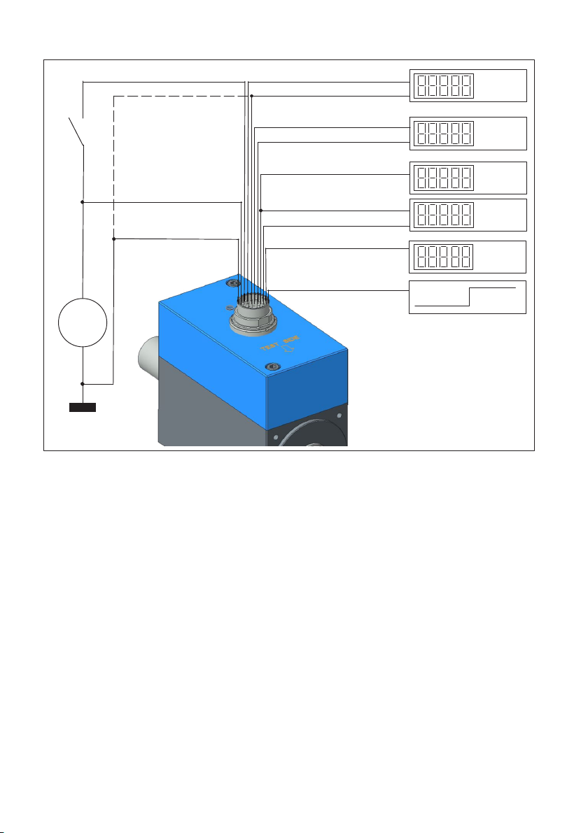
The T210torque transducer is used exclusively for torque and rotation speed measure
ment tasks, and directly associated control and regulatory tasks. Use for any purpose
other than the above is deemed improper use.
In the interests of safety, the transducer should only be operated as described in the
Operating Manual. During use, compliance with the legal and safety requirements for the
relevant application is also essential. The same applies to the use of accessories.
The transducer is not a safety element within the meaning of appropriate use. Proper and
safe operation of this transducer requires proper transportation, correct storage, assem
bly and mounting, and careful operation.
General dangers of failing to follow the safety instructions
The transducer corresponds to the state of the art and is failsafe. The transducer can
give rise to remaining dangers if it is inappropriately installed and operated by untrained
personnel.
Everyone involved with mounting, starting up, maintaining, or repairing the transducer
must have read and understood the Operating Manual and in particular the technical
safety instructions.
Residual dangers
The scope of supply and performance of the transducer covers only a small area of
torque measurement technology. In addition, system planners, installers and operators
should plan, implement and respond to the safety engineering considerations of torque
measurement technology in such a way as to minimize remaining dangers. Existing regu
lations must be complied with at all times. Reference must be made to remaining dan
gers connected with torque measurement technology.
Conversions and modifications
The design or safety engineering of the transducer must not be modified without our ex
press permission. Any modification shall exclude all liability on our part for any resulting
damage.
Qualified personnel
The transducer must only be installed and used by qualified personnel, strictly in accor
dance with the specifications and with safety requirements and regulations. During use,
compliance with the legal and safety requirements for the relevant application is also
essential. The same applies to the use of accessories.

T210
SAFETY INSTRUCTIONS
4
Qualified personnel means persons entrusted with siting, mounting, starting up and oper
ating the product who possess the appropriate qualifications for their function.
Accident prevention
According to the prevailing accident prevention regulations, once the torque transducers
have been mounted, a covering agent or cladding has to be fitted as follows:
SThe covering agent or cladding must not be free to rotate.
SThe covering agent or cladding should prevent squeezing or shearing and provide
protection against parts that might come loose.
SCovering agents and cladding must be positioned at a suitable distance or be so ar
ranged that there is no access to any moving parts within.
SCovering agents and cladding must still be attached even if the moving parts of the
torque transducer are installed outside peoples' movement and working range.
The only permitted exceptions to the above requirements are if the various parts and as
semblies of the machine are already fully protected by the design of the machine or by
existing safety precautions.

5
T210
MARKINGS USED
2 MARKINGS USED
2.1 Markings used in this document
Important instructions for your safety are highlighted. Following these instructions is es
sential in order to prevent accidents and damage to property.
Icon Meaning
CAUTION This marking warns of a potentially dangerous situa
tion in which failure to comply with safety require
ments could result in slight or moderate physical in
jury.
Notice This marking draws your attention to a situation in
which failure to comply with safety requirements
could lead to property damage.
Information This marking draws your attention to information
about the product or about handling the product.
Emphasis
See …
Italics are used to emphasize and highlight text and
identify references to sections of the manual, dia
grams, or external documents and files.
uThis symbol indicates an action step.
2.2 Symbols on the device
CE mark
The manufacturer declares on his own responsibility that the
product conforms to the essential requirements of the applicable
harmonization legislation of the Union, and that the relevant
conformity assessment procedures have been fulfilled.
UKCA marking
The manufacturer declares on his own responsibility that the
product conforms to the essential requirements of the applica
ble United Kingdom legislation, and that the relevant conformity
assessment procedures have been fulfilled.
Statutory end-of-life disposal indicator
Products must be properly disposed of in accordance with na
tional and local environmental protection and material recovery
regulations. The products are not suitable for disposal with
household waste.

T210
MARKINGS USED
6
Product literature
To avoid risks, all precautions, warnings, and operating instruc
tions contained in the product literature, especially in the instruc
tions for use, must be carefully read, fully understood and fol
lowed before installing, commissioning, and/or using the
product, and before performing any maintenance on the product.
Failure to comply may result in risks due to improper use of the
product.
Marking in accordance with the requirements of SJ/T 11364-2014 and SJ/T
11363-2006 (“China RoHS-2”)
Marking for products containing hazardous substances in quan
tities above the maximum concentrations.
Assembly
Hazardous substance / 有害物质
Lead
(Pb)
Merc
ury
汞
(Hg)
Cadmi
um
(Cd)
Hexavalent
chromium
六
(Cr (VI))
Poly
brominated
biphenyls
多溴联苯
(PBB)
Polybrominated
diphenyl ethers
多溴苯
(PBDE)
Measuring body/
shaft
O O O O O O
Housing O O O O O O
Electronic com
ponents/PCB
O O O O O O
Small parts (e.g.
screws, pins,
receptacles)
X O O O O O
This table was compiled in accordance with the requirements of SJ/T 11364.
本表格照SJ/T 11364规定的规定编制。
O: Signifies that the amount of hazardous substance in question within the homoge
neous substances of the assembly is less than the limit value according to
GB/T 26572.
该有毒有害物质在该部件所有均质材料中的含量均在
GB/T 26572规定的。
X: Signifies that the amount of at least one of the hazardous substances within the ho
mogeneous substances of the assembly is above the limit value according to GB/
T 26572.
该有毒有害物质至少在该部件的某一均质材料中的含量超出
GB/T 26572规定。

7
T210
APPLICATION
3 APPLICATION
The T210torque transducer measures static and dynamic torques and rotational speeds
or angles of rotation on rotating or stationary machine parts with any direction of rota
tion. It is designed for low to medium torques, such as those measured in performance or
function testing rigs for household appliances or office machines.
Use is only permitted in closed rooms and cables must not be installed outdoors.

T210
MOUNTING
8
4 MOUNTING
4.1 Mounting position
The torque transducer can be mounted in any position (see also chapter 4.3.1).
4.2 Mounting options
CAUTION
The permissible load limits specified in the technical data (see chapter 10) must be
strictly observed.
Ó
Ó
Ó
ÔÔÔÔÔÔÔ
ÔÔÔÔÔÔÔ
Ô
Ô
ÓÓ
F
Foot mounting be
tween two full cou
plings
Face mounting (mea
suring side), right full
clutch, left belt opera
tion
1) HBM accessories: Bellows couplings. Two of the available couplings are required
2) HBM accessories: Bellows couplings. One of the available couplings is required
Fig. 4.1 Mounting options with couplings

9
T210
MOUNTING
4.3 Couplings
HBK offers bellows couplings for installation of the torque transducer. The following
points must be observed when installing:
1. Degrease the hub hole in each coupling half and the shaft ends with solvent (e.g. ace
tone).
2. Push the hub onto the shaft.
3. Adjust the air gap to the transducer, which should be min. 1mm from the transducer
housing, or push the coupling onto the shaft until it reaches the limit stop.
4. Using the full clamping length, align the coupling and shafts.
5. Tighten the clamping bolts of the clamp with a torque wrench (see Specifications for
the required torque).
Notice
Do not tighten the clamping bolts of the couplings until the shafts have been installed in
the coupling hubs!
The bellows coupling must not be stretched beyond the permissible compliance.
Input and output shafts must be free of grease and burrs.
Make the shaft diameters with j6 tolerance to obtain the preferred H7/j6 fit.
When selecting the coupling, the specifications of the transducer – and in particular the
maximum permissible mechanical stresses – must be taken into account in addition to the
specifications of the coupling.
4.3.1 Mounting position with couplings
The T210torque transducer can be operated with bellows couplings in any mounting po
sition (horizontally, vertically or at an angle). Please ensure that additional masses are
adequately supported during vertical and inclined operation.
The specifications and the mounting instructions for the couplings can be found in the
data sheet of the bellows couplings.
CAUTION
The permissible axial and lateral forces and the bending moment limits of the torque trans
ducer must not be exceeded when mounting couplings!
Brace the coupling by the clamp when tightening the clamping bolts.

T210
ELECTRICAL CONNECTION
10
5 ELECTRICAL CONNECTION
5.1 General information
For the electrical connection between the torque transducer and measuring amplifier we
recommend using shielded, low-capacitance measuring cables.
With extension cables, make sure that there is a proper connection with minimum contact
resistance and good insulation. All plug connections or swivel nuts must be tightened
firmly.
Do not route the measurement cables parallel to power lines and control circuits. If this
cannot be avoided (in cable pits, for example), maintain a minimum distance of 50 cm
and also draw the measuring cable into a steel tube.
Avoid transformers, motors, contactors, thyristor controls and similar stray-field sources.
5.2 Connector plug
The transducer is equipped with a permanently mounted housing connector.
It can be connected to the corresponding measurement electronics via the transducer
connection cable (available as an accessory). Please refer to the following table for the
pin assignment of the transducer connection cables.

11
T210
ELECTRICAL CONNECTION
Pin Assignment Wire
color
Trigger
control sig
nal (with
out VK20A)
Switch
(NO)
ATorque measurement signal (fre
quency output; 5 V)1) 2) bk
BRotational speed/angle of rotation
measurement signal A; 5 V
rd
CTorque measurement signal ±10 V br
DTorque measurement signal 0 V wh
EGround (supply+rotational speed/an
gle of rotation)
ye
FSupply voltage 10 V … 30 V vt
GRotational speed/angle of rotation
measurement signal B; 5 V; lagging by
90°
gn
HRotational speed reference signal Z;
5 V
pk
JMeasurement signal - ready for mea
surement
gr
KControl signal triggering gy/pk
LTorque measurement signal (fre
quency output; 5V)1), 2) bl/rd
MNot in use bl
1) Complementary signals RS-422. Problems with signal quality can be mitigated by a termination resistor
(R=120 Ohm) between the wires (bl) and (bl/rd).
2) RS-422: Pin A corresponds to A, pin L corresponds to B

T210
ELECTRICAL CONNECTION
12
low high
degr.
Angle of track B (pin G)
Angle of track A (pin B)
rpm
Rotational speed output
(pin B)
Nm
Frequency output (pin L)
Frequency output (pin A)
Nm
Torque ground (pin D)
Torque (pin C)
U=
Supply ground (pin E)
Supply (pin F)
Control (pin K)
The supply ground and
moment ground can
be combined at source
if required.
rpm
Reference signal Z (pin H)
Measurement signal -
ready for measurement
Fig. 5.1 Connection diagram T210
The transducer generates an internally electrically isolated measurement signal. The
grounds must not be bridged directly on the transducer, otherwise measurement errors
may occur depending on the supply and analysis device. If necessary they can be bridged
on the supply and analysis device. The "control signal" is used to test the transducer. It is
connected to the torque outputs at 50% of the nominal signal. The modulation level is
4.5 V up to the supply voltage. The reference voltage is the supply ground.
The transducer has a ready for measurement signal. If the output is returning a HIGH
level, normally the measurement electronics are working. With a LOW level there is an
error.
5.3 Extending the cable
Extension cables must be shielded and of low capacitance.
With cable extensions it is important to ensure that a good connection is provided, with
minimum contact resistance and good insulation. So all connections should be soldered,
or at least made with secure, stable clamp terminals or screwed plug connectors.

13
T210
ELECTRICAL CONNECTION
Measuring cables should not be laid parallel to power cables and control circuits (that is,
not in shared cable ducts). If this is not possible, protect the measurement cable with a
rigid steel conduit, for example, and keep it as far away from other cables as possible.
Avoid stray fields from transformers, motors and contact switches.
Notice
At the maximum rotational speed of 30,000 rpm the cable length is limited to maximum
10 m.
5.4 Shielding design
The cable shield is connected in accordance with the Greenline concept. This encloses
the measurement system in a Faraday cage. It is important that the shield is laid flat on
the housing ground at both ends of the cable. Any electromagnetic interference active
here does not affect the measurement signal.
In the event of interference due to potential differences (compensating currents), discon
nect supply voltage zero from the housing ground at the measuring amplifier and lay a
potential equalization line between the transducer housing and the measuring amplifier
housing (copper cable, 10 mm2cable cross-section).
5.5 Status LED
The transducer has a status LED. The various states are shown in table Tab. 5.1.
LED Description Analog output
signals
Output
status
Flashing blue Boot-up
Measurement shaft is started.
-14 V and 0 Hz LOW
Lit green Ready for operation
Measurement shaft ready for
measurement.
Measurement
signal
HIGH
Flashing red Warning
Non-critical state. Technical spec
ifications are no longer guaran
teed.
Measurement
signal
LOW
Lit red Error
Critical state. Stop operation.
Error signal LOW
Tab. 5.1 Various LED states

T210
LOAD-CARRYING CAPACITY
14
6 LOAD-CARRYING CAPACITY
The T210can be used to measure static and dynamic torques.
Nominal (rated) torque can be exceeded statically up to the torque limit. If the nominal
torque is exceeded, additional irregular loading is not permissible. This includes axial
force and lateral forces and bending moments. The limit values can be found in chapter
10 "Specifications", page 22.
6.1 Measuring dynamic torque
When measuring dynamic torques, please note:
SThe calibration performed for static torques is also valid for dynamic torque measure
ments.
Notice
The frequency of the dynamically acting torques must be lower than the natural fre
quency of the mechanical measuring arrangement.
SThe natural frequency f0of the mechanical measuring arrangement depends on the
moments of inertia J1and J2of the two connected rotating masses and the torsional
stiffness of the transducer.
The equation below can be used to determine the natural frequency f0of the mechanical
measuring arrangement.
f0= natural frequency in Hz
J1, J2= moment of inertia in kg·m2
cT= torsional stiffness in N·m/rad
f0+1
2p<cT<ǒ1
J1)1
J2Ǔ
Ǹ
SThe oscillation width (peak-to-peak) may be max. 80% of the nominal (rated) torque of
the torque transducer, even under alternating load. The oscillation width must fall
within the loading range specified by -MNand +MN.

15
T210
LOAD-CARRYING CAPACITY
0
45
35
Torque in MNin %
+MN100
-MN100
80% MNoscil
lation width
Upper torque limit
Lower torque limit
Fig. 6.1 Permissible dynamic loading
6.2 Rotational speed
A slotted disk is installed on the loaded member. This is scanned by an encoder in the
housing. The T210returns two 90° offset square wave signals with 512 pulses per revolu
tion at the output. Detection of the direction of rotation is possible with this angle. In
clockwise rotation, channel B (pin G) lags channel A (pin B) by 90°.
Channel A
(pin B, red)
Channel B
(pin G,
green)
U (5 V)
U (5 V)
t
t
Fig. 6.2 Detection of rotational speed and direction of rotation

T210
LOAD-CARRYING CAPACITY
16
The rotational speed reference signal Z is additionally outputted on pin H. It is also a 5 V
square wave signal. At 1 pulse per revolution, it is suitable for measuring high rotational
speeds, as this places lower demands on the evaluation unit.
Information
The T210torque transducers are suitable for a nominal (rated) rotational speed of max.
30,000 rpm depending on the nominal (rated) measuring range.
Tip
To ensure an optimum distribution of grease in the bearing, turning the measurement shaft
once before the start of the measurement with the maximum expected rotational speed is
recommended.

17
T210
TORQUE AND DIRECTION OF ROTATION DISPLAY
7 TORQUE AND DIRECTION OF ROTATION DISPLAY
Torque
If a clockwise torque is introduced, an output signal from 0...+10 V or 10…15 kHz is
present.
Direction of rotation
The sign of the display indicates the direction of rotation. On HBM amplifiers, the output
voltage and reading is positive when the measurement shaft is rotated clockwise facing
the measuring side.
Fig. 7.1 Direction of rotation for positive reading

T210
MAINTENANCE
18
8 MAINTENANCE
The T210torque transducer is largely maintenance-free. We recommend having the low-
friction special bearings replaced at the factory after approximately 20,000 operating
hours. It is also a good idea to have a calibration performed at this point at the latest.
Table of contents
Languages:
Other HBK Transducer manuals
Popular Transducer manuals by other brands

S+S Regeltechnik
S+S Regeltechnik AERASGARD RCO2-W operating instructions

Simrad
Simrad 50-7 - INSTALLATION REV A installation manual

Omega
Omega PX540 Series Operator's manual

Raymarine
Raymarine Transducers user guide

turck
turck IM33-14Ex-CDRi manual

Simrad
Simrad ES200-7C - INSTALLATION REV B installation manual