GHM-Martens MU125 User manual

Operating manual
Temperature measuring
transducer
MU125
Save for later reference.
www.ghm-messtechnik.de
Company / brands of GHM
English

GHM Messtechnik GmbH
–
Stan ort Martens
iebitzhörn 18 ● 22885 Barsbüttel ● Germany
Phone +49-40-670 73-0 ● Fax -288
www.ghm-messtechnik.de ● [email protected]
2
Table of contents Page
1. Inten e use (areas of application) ................................................................. 3
1.1 Safety signs and symbols ........................................................................ 3
1.2 Safety instructions .................................................................................... 4
1.3 Product liability and warranty ................................................................... 4
1.4 Standards and directives .......................................................................... 4
2. Pro uct escription .......................................................................................... 5
2.1. Scope of delivery ...................................................................................... 5
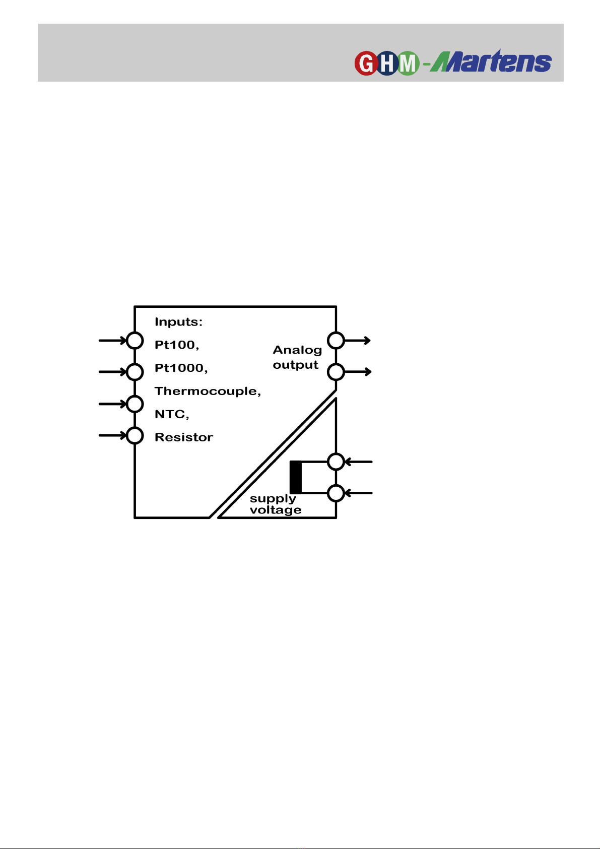
2.2. Functional principle .................................................................................. 6
2.3. Connection diagram ................................................................................. 6
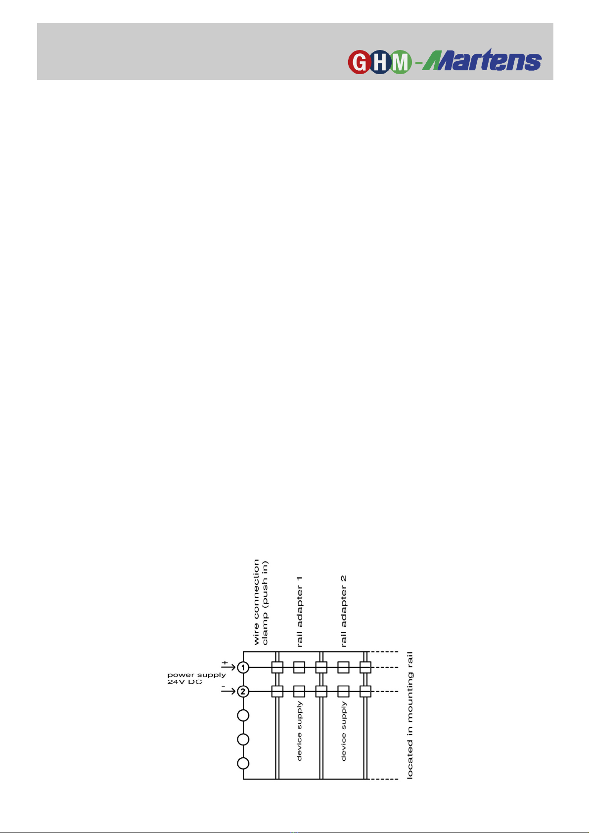
2.4. PowerRail ................................................................................................. 7
2.5. Type plate ................................................................................................ 8
3. Assembly an installation ................................................................................ 9
3.1. Mechanical assembly ............................................................................... 9
3.2. Electrical installation ................................................................................. 9
4. Functional escription.................................................................................... 10
4.1 Controls .................................................................................................. 10
4.2 Service mode ......................................................................................... 12
4.21 Check of factory settings ............................................................. 12
4.22 Output characteristic curve specification ..................................... 13
4.23 Current simulation ....................................................................... 15
5. Commissioning, maintenance an service .................................................. 16
5.1 Commissioning ....................................................................................... 16
5.2 Maintenance ........................................................................................... 16
5.3 Service ................................................................................................... 16
6. Technical ata ................................................................................................. 17
6.1 Mechanical design / dimensions ............................................................ 19
7. Or er co e ....................................................................................................... 20
8. Device transport an storage ........................................................................ 20
9. Return to manufacturer .................................................................................. 21
10. Disposal ................................................................................................ 21
11 Imprint .............................................................................................................. 21
12. Certificate of Conformity ..................................................................... 22

GHM Messtechnik GmbH
–
Stan ort Martens
iebitzhörn 18 ● 22885 Barsbüttel ● Germany
Phone +49-40-670 73-0 ● Fax -288
www.ghm-messtechnik.de ● [email protected]
3
Danger
1. Inten e use (areas of application)
Refer to the chapter 'Product description' for detailed specifications for
the area of application.
The operational safety of the device is only assured when used as
intended in accordance with the specifications in the operating manual.
Intervention beyond the actions described in the operating manual may only be
carried out by personnel authorised by the manufacturer for safety and warranty
reasons. Conversions or modifications made on one's own authority are expressly
prohibited.
Application-specific dangers can emanate from this device when used
improperly or not as intended.
The device is not suitable for use in explosion-prone areas.
General safety instructions, use
This operating manual must be kept in a location such that qualified personnel can
refer to it at all times.
Any processes described in this operating manual may only be carried out by
trained, qualified personnel who are authorised by the owner and wearing
protective clothing. All rights reserved.
1.1 Safety signs an symbols
Warning notices are identified in this document as described under Table 1:
Warning! This symbol warns of imminent danger which can result
in death, severe bodily injury, or severe property damage in case
of non-observance.
Attention! This symbol warns of potential dangers or harmful
situations which can cause damage to the device or to the
environment in case of non-observance.
Note! This symbol indicates processes which can have a direct
influence on operation or can trigger an unforeseen reaction in
case of non-observance.

GHM Messtechnik GmbH
–
Stan ort Martens
iebitzhörn 18 ● 22885 Barsbüttel ● Germany
Phone +49-40-670 73-0 ● Fax -288
www.ghm-messtechnik.de ● [email protected]
4
1.2 Safety instructions
Read the product description before commissioning the device. Ensure that there
are no limitations for use of the product for the relevant applications.
The owner is responsible for ensuring the fault-free operation of the
device. The owner is obligated to ensure compliance and to observe
the required work and safety measures of the current applicable
regulations for the entire duration of use.
1.3 Pro uct liability an warranty
Exclusion of liability:
The contents of the operating manual have been checked to ensure conformity with
the described device. However, deviations cannot be entirely ruled out. Therefore,
we cannot assume any guarantee for complete conformity. The specifications in
this document are checked regularly and any necessary corrections are
incorporated into subsequent versions. This document is subject to technical
changes. In addition, all claims are based on the valid 'Standard Terms for the
Supply of Products and Services of the Electrical Industry'.
GHM Messtechnik cannot inspect or repair any devices without the
required form having been filled in completely (see chapter "Return").
1.4 Stan ar s an irectives
Low-voltage Directive 2014/35/EU
Testing standard 60664-1: 2007
EMC Directive 2014/30/EU
Testing standard EN 61326-1: 2013
RoHS Directive 2011/65/EU
Testing standard EN50581: 2012
(Issue years for testing standards belong to german versions)
DANGER

GHM Messtechnik GmbH
–
Stan ort Martens
iebitzhörn 18 ● 22885 Barsbüttel ● Germany
Phone +49-40-670 73-0 ● Fax -288
www.ghm-messtechnik.de ● [email protected]
5
2. Pro uct escription
Temperature measuring transducers of the series MU125 convert a temperature
measurement value or resistance measurement value from various sensors to a
current signal of 4..20mA.
The universal configurability of the measuring inputs reduces the stock requirement for
various applications.
The measuring inputs and the analog output are galvanically isolated.
The housing width of only 12.5mm enables space-saving installation in the switch
cabinet.
2.1. Scope of elivery
• MU125
• This operating manual
• Additional documents, if applicable

GHM Messtechnik GmbH
–
Stan ort Martens
iebitzhörn 18 ● 22885 Barsbüttel ● Germany
Phone +49-40-670 73-0 ● Fax -288
www.ghm-messtechnik.de ● [email protected]
6
2.2. Functional principle
An analog output value with 4..20 mA is actuated depending on the selected
measuring range.
The temperature measuring ranges are linearised.
The device configuration is carried out with DIP switches.
The device can be supplied in a wide range between 20..125V DC or 20..253V AC.
A low cost version with 24V DC power supply is available.
Another version allows a 24V power supply via a mounting rail bus (Power Rail)
.
2.3. Connection iagram
The input signal should be connected via separate two-wire or three-
wire conductors.
Earthed conductors can cause faults at an analog actual value output
that is not galvanically isolated.

GHM Messtechnik GmbH
–
Stan ort Martens
iebitzhörn 18 ● 22885 Barsbüttel ● Germany
Phone +49-40-670 73-0 ● Fax -288
www.ghm-messtechnik.de ● [email protected]
7
2.4. PowerRail
The supply of multiple devices can be combined and simplified via a bus system
in the carrier rail (TS35).
A corresponding version is available for the entire LP series of GHM carrier rail
devices in a housing with 12.5 mm width.
A bus adapter compatible with series connection is clamped on the carrier rail
before installation of the device to be supplied with power.
An adapter is required for each device. The bus power supply is provided via a
plug-type terminal strip.
The power supply terminals 11 and 12 on the upper device side are omitted in
device version MU125LP designed for this purpose.

GHM Messtechnik GmbH
–
Stan ort Martens
iebitzhörn 18 ● 22885 Barsbüttel ● Germany
Phone +49-40-670 73-0 ● Fax -288
www.ghm-messtechnik.de ● [email protected]
8
2.5. Type plate
The type plate provides the most important identification data
● Type and article designation
● Technical data
● Serial number / bar code
Fig. 3: Type plate

GHM Messtechnik GmbH
–
Stan ort Martens
iebitzhörn 18 ● 22885 Barsbüttel ● Germany
Phone +49-40-670 73-0 ● Fax -288
www.ghm-messtechnik.de ● [email protected]
9
3. Assembly an installation
3.1. Mechanical assembly
Carrier rail mounting TS35, DIN EN 60715
The gapless installation of multiple devices is only possible with a horizontally
installed carrier rail.
3.2. Electrical installation
The device may only be installed by an electrician. Compliance with
the national and international regulations for installation of electrical
and electronic systems applicable in the respective country of use is
mandatory.
Voltage supply in accordance with DIN EN60664-1, SELV, PELV.
Observe the connection diagram for installation of inputs and outputs.
The supply voltage connection is made at connections 11 and 12 of the plug-type
terminal strip.
Terminals 41, 42, 51 and 52 are provided for sensor connection
Terminals 61 and 62 are provided for analog true value output
DANGER
Fig. 4

GHM Messtechnik GmbH
–
Stan ort Martens
iebitzhörn 18 ● 22885 Barsbüttel ● Germany
Phone +49-40-670 73-0 ● Fax -288
www.ghm-messtechnik.de ● [email protected]
10
4. Functional escription
4.1 Controls
Operation LED states
Green continuous light: Normal operation.
Red slow blinking (one-second frequency): Errors at the measuring inputs
In service mode
Red continuous light: The trim potentiometer is positioned at the factory
setting.
(red light differs from normal operation)
Red rapid blinking: Position of the trim potentiometer is positioned
above the calibrated factory setting.
Turn anti-clockwise to reach the factory setting.
Green rapid blinking: Position of the trim potentiometer is positioned
below the calibrated factory setting.
Turn clockwise to reach the factory setting.

GHM Messtechnik GmbH
–
Stan ort Martens
iebitzhörn 18 ● 22885 Barsbüttel ● Germany
Phone +49-40-670 73-0 ● Fax -288
www.ghm-messtechnik.de ● [email protected]
11
The measuring range is selected with the DIP switches:
Pt100, Pt1000, thermocouple (type J, type , type S) , NTC and linear
resistance.
The black fields symbolise the position of the DIP switch
Sensor break an sensor short circuit
Monitoring for sensor breaks and short circuits also takes place in the measuring
ranges for Pt100 and Pt1000 sensors.
In this case, the relays become inactive and the scale light blinks red.
The analog output drops to approx. 0mA.
Trim potentiometer
The 12-turn trim potentiometer can
re uce the en value by 50%
and
change the zero point (start value) by +/- 40% base on the
factory measuring range
(= factory en value - factory start value)

GHM Messtechnik GmbH
–
Stan ort Martens
iebitzhörn 18 ● 22885 Barsbüttel ● Germany
Phone +49-40-670 73-0 ● Fax -288
www.ghm-messtechnik.de ● [email protected]
12
There is also a service mode for the trim potentiometer offering the following
possibilities:
a) A check of whether potentiometers are positioned at the calibrated factory settings
b) The pre-adjustment of a new output characteristic curve with connection of a
current measuring device. (A temperature calibrator is not necessary)
c) Specification of a constant value at the current output, e.g. in order to test the
reaction of connection devices.
The trim potentiometers can be use in both normal operation an service
mo e.
4.2 Service mo e
A corresponding service mode can be selected for each of the two trim
potentiometers via the DIP switches.
4.21 Check of factory settings
- If the selected potentiometer is positioned at the calibrated factory setting,
the operation LED illuminates red (continuously).
- If the potentiometer is above the calibrated factory setting, the operation LED
blinks red.
- If the potentiometer is below the calibrated factory setting, the operation LED blinks
green.
(Since the end value can only be reduced, the green blinking is omitted)

GHM Messtechnik GmbH
–
Stan ort Martens
iebitzhörn 18 ● 22885 Barsbüttel ● Germany
Phone +49-40-670 73-0 ● Fax -288
www.ghm-messtechnik.de ● [email protected]
13
4.22 Output characteristic curve specification
Settings for a deviating measuring range can be made without using a
temperature calibrator
For this purpose, the respective trim potentiometer is couple irectly to the
analog output and generates a current proportional to the setting.
Value range
The current output can basically generate a current in the range of 4..20mA. The
current range is thus 16mA. (20mA minus 4mA)
As a result, the following classifications arise for a current change:
A change of the
input signal by
100% 50% 40% 30% 20% 10% 1%
results in an
output voltage
change of
16mA 8mA 6.4mA 4.8mA 3.2mA 1.6mA 0.16mA
The position of the assigned trim potentiometer simulates the input signal in the 2
service modes.
Re uction of the measuring range en value
The measuring range end value can be reduced by up to 50% below the factory
end value. This process is simulated in service mode with an output current
controlled by the trim potentiometer.
Without reduction of the factory end value, which corresponds to the end position
of the trim potentiometer, a constant current of 20mA is provided at the output in
service mode. The operation LED then illuminates red (continuous light).
The - trim potentiometer must be turned clockwise *) for a reduction of the
measuring range end value. The operation LED then blinks red.
According to the table above, for reducing the end value by
- 20% the output current must be reduced by 3,2mA down to 16,8mA
- 50% the output current must be reduced by 8mA down to 12mA
*) The clockwise rotation is based on the behaviour in normal measuring operation: The output current based on the actual value
increases with clockwise rotation,but this results in a smaller measuring range.

GHM Messtechnik GmbH
–
Stan ort Martens
iebitzhörn 18 ● 22885 Barsbüttel ● Germany
Phone +49-40-670 73-0 ● Fax -288
www.ghm-messtechnik.de ● [email protected]
14
Change of the measuring range start value
The start value can be changed by +/-40% based on the factory measuring range
(= factor end value - factor start value).
In order to show the potential change of the start value on the output current
range, a virtual zero point of 12mA *) is assumed.
This output current is generated in service mode if the trim
potentiometer is positioned at the calibrated factory setting.
The trim potentiometer is then in the centre position. The operation LED
illuminates red (continuous light).
*) If the factory zero point were based on 4mA, the output current for the simulation of a reduction by 40% would have to be negative,
which is not technically possible
According to the value range table on the preceding page, for a change of the
start value by
-40% the output current must be reduced by turning anticlockwise 6.4mA down to
5.6mA (12mA - 6.4mA = 5.6mA)
-10% the output current must be reduced by turning anticlockwise 1.6mA down to
10.4mA (12mA - 1.6mA = 10.4mA)
+10% the output current must be increased by turning clockwise 1.6mA up to
13.6mA (12mA + 1.6mA = 13.6mA)
+40% the output current must be increased by turning clockwise 6.4mA up to
18.4mA (12mA + 6.4mA = 18.4mA)
The operation LED blinks green with a reduction and red with an increase.
Note:
The device can only detect a minimum measurement temperature of -50°C in
most measuring ranges (refer to "Technical data" for more information).
Therefore, a reduction of the start value by -40% only makes sense in the factory
measuring ranges of 0..50°C, 0..100°C and -20..40°C. However, since the device
can not recognise the measuring range to be applied later after leaving the
service mode, a reduction by -40% can always be adjusted in this mode.
In reality the device would switch off the output if the measuring temperature is too
low (approx. 0mA).
Examples
1) A measuring range of 0..500°C should be changed to 0..400°C.
For this purpose, the factory end value must be reduced by 20%
(1 - 400°C / 500°C = 0.20 = 20%).
The value range table on the previous page shows that in service mode a
reduction of the output current by 3,2mA must take place.
Therefore, an output current of 16.8mA must be adjusted (20mA – 3.2mA =
16.8mA) in service mode by the trim potentiometer.
In service mode for the trim potentiometer the factory setting of 12mA
should be left.

GHM Messtechnik GmbH
–
Stan ort Martens
iebitzhörn 18 ● 22885 Barsbüttel ● Germany
Phone +49-40-670 73-0 ● Fax -288
www.ghm-messtechnik.de ● [email protected]
15
2) A measuring range of 0..100°C should be changed to -25..60°C.
For this purpose, the measuring range end value must be reduced by 40%.
(1 - 60°C / 100°C = 0.4 = 40%)
Based on the value range table on page 13, the output current must be
reduced (in service mode) by 6.4mA for a reduction of the end value by 40%.
Therefore, an output current of 13.6mA must be adjusted (20mA – 6.4mA =
13.6mA) with the trim potentiometer.
To calculate the adjustment for the measuring range start value, the factory
measuring range is determined first (factory end value - factory start value):
100°C – 0°C = 100°C.
(negative start values must be added because of the double sign)
The measuring range start value should then be reduced by 25°C based on the
measuring range, which then also necessitates a reduction of the output current
by 25% in service mode.
This value is multiplied by the greatest possible current change of 16mA: 16mA
* 25% = 4mA
Therefore, an output current of 8mA must be adjusted in service mode for the
trim potentiometer.
(virtual zero point at 12mA minus 4mA reduction = 8mA)
Accuracy
A reduction of the end value or an increase of the start value always reduces the
measuring accuracy.
The (in)accuracy values specified in the "Technical data" thus increase by the
factor:
factory end value – factory start value (divided by)
(adjusted end value) – (adjusted start value)
(negative start values must be added because of the double sign)
4.23 Current simulation
The change of the output current proportional to the trim potentiometer setting in
service mode can also be used to simulate an action which should appear in
normal mode.
An output current in the range of 5.6mA to 18.4mA can be simulated with the
potentiometer.
The potentiometer can simulate an output current in the range of 10mA to
20mA.
After the simulation, the potentiometers must then be turned back to the original
position, i.e. the factory setting.

GHM Messtechnik GmbH
–
Stan ort Martens
iebitzhörn 18 ● 22885 Barsbüttel ● Germany
Phone +49-40-670 73-0 ● Fax -288
www.ghm-messtechnik.de ● [email protected]
16
5. Commissioning, maintenance an service
5.1 Commissioning
1. Ensure that the connections have been made as indicated in the connection
diagram and the supply voltage is correct.
2. Ensure that the terminals are firmly screwed in.
3. After switching on the power supply, check to ensure the operation.
5.2 Maintenance
Housing:
No cleaning or maintenance is required when operated as intended.
5.3 Service
Service of the device is only possible in the factory.

GHM Messtechnik GmbH
–
Stan ort Martens
iebitzhörn 18 ● 22885 Barsbüttel ● Germany
Phone +49-40-670 73-0 ● Fax -288
www.ghm-messtechnik.de ● [email protected]
17
6. Technical ata
Wi e-range power supply
Supply voltage : 20..125VDC and
20..250VAC (47..63Hz), max.1.5W
24V power supply
Supply voltage : 24V DC +/-15%, max. 1.5W
Combine ata
Rated voltage- : 253V AC (in accordance with EN 60664-1; Degree of
contamination 2, Overvoltage category II)
Test voltage : 3kV AC between supply voltage // input = output
Working temperature
: -10..60°C
Storage temperature
: -20..80°C
Air humidity : 10..90% (no condensation)
EMC : in accordance with EN 61326-1
Measurement inputs
Pt100 : linearised,
Measuring current approx. 1.6mA
Pt1000 : linearised,
Measuring current approx. 130µA
In the event of a sensor break or short circuit, the analog
output drops to 0mA. The operation LED blinks red
Thermocouple : linearised with comparison position compensation
(optionally without internal compensation)
NTC : linearised for B25/85=3977 or 3528
Max. load 200µW (averaged)
Linear resistance : MR. 0..2kΩ: approx. 1.4mA
MRs. 0..5kΩ, 0..10kΩ: approx. 300µA
Zero point setting : +/-40% of the factory measuring range (= end value – start
value) via 12-turn trim potentiometer
End value reduction : -50% based on the factory end value
via 12-turn trim potentiometer
Potentiometer : Limitation of the aforementioned adjustment ranges
setting limits
Pt100 -50..500°C (..600°C)
Pt1000 -50..250°C (..300°C)
FeCuNi -100..500°C (..800°C)
NiCrNi -150..1250°C
PtRhPt 0..1500°C (..1600°C)
NTC (10kΩ) -20..100°C (..150°C)
NTC ( 2kΩ) -40..100°C (-50°C..150°C)
R linear 0..10kΩ
(values in parentheses apply for optional, customer-specific
special measuring ranges that are configured at the factory)

GHM Messtechnik GmbH
–
Stan ort Martens
iebitzhörn 18 ● 22885 Barsbüttel ● Germany
Phone +49-40-670 73-0 ● Fax -288
www.ghm-messtechnik.de ● [email protected]
18
Analogue output : 4..20mA, max. burden 400Ω,
No galvanic isolation from the input signal
(max. burden error of 0.2% at 400Ohm)
*) Measurement deviation depending on the environmental temperature
in the switch cabinet (-10..+60°C)
Measuring
range
Basic
accuracy
Temperature
deviation *)
Pt100 -50.. 50°C 0.4% 0.01%/
0.. 50°C 0.6% 0.02%/
0..100°C 0.4% 0.02%/
0..150°C 0.4% 0.01%/
0..200°C 0.3% 0.01%/
0..250°C 0.3% 0.01%/
0..300°C 0.2% 0.005%/
0..500°C 0.2% 0.005%/
Pt1000 -50.. 50°C 0.4% 0.01%/
-30.. 70°C 0.4% 0.01%/
-20.. 40°C 0.4% 0.01%/
0.. 50°C 0.6% 0.02%/
0..100°C 0.4% 0.02%/
0..150°C 0.4% 0.01%/
0..200°C 0.3% 0.01%/
0..250°C 0.3% 0.005%/
FeCuNi 0..250°C 1.0% 0.04%/
0..500°C 0.5% 0.03%/
NiCrNi -50..250°C 0.7% 0.05%/
0..500°C 0.5% 0.04%/
0..750°C 0.4% 0.03%/
0..1000°C
0.3% 0.02%/
0..1250°C
0.3% 0.02%/
PtRhPt 0..1500°C
1.0% 0.04%/
NTC
R25=10kΩ
B
25/85
=3977
0..100°C 1.0% 0.01%/
NTC
R25=10kΩ
B
25/85
=3977
-20..50°C 1.5% 0.01%/
NTC
R25=2kΩ
B25/85=3528
0..100°C 1.0% 0.01%/
Resistance
linear
0.. 2kΩ 0.3% 0.005%/
0.. 5kΩ 0.5% 0.01%/
0..10kΩ 0.3% 0.005%/

GHM Messtechnik GmbH
–
Stan ort Martens
iebitzhörn 18 ● 22885 Barsbüttel ● Germany
Phone +49-40-670 73-0 ● Fax -288
www.ghm-messtechnik.de ● [email protected]
19
Casing
Dimensions (WxDxH) : 12.5 x 114 x 108 mm
Material : PA6.6, light grey, Flammability class V0 (UL94)
Weight : 120 g
Protection rating : IP20
Screw terminals : 0.2..2.5 mm², AWG 24 - 14, removable, coded
Push-in terminals : 0.5..1.5 mm², AWG 25 - 16, double connection
(spring-type terminals) (12A between the connections),
removable, coded
Power Rail : 8A over the entire bus system
(power supply via removable terminals
0.2..2.5 mm², AWG 24..14)
6.1 Mechanical esign / imensions

GHM Messtechnik GmbH
–
Stan ort Martens
iebitzhörn 18 ● 22885 Barsbüttel ● Germany
Phone +49-40-670 73-0 ● Fax -288
www.ghm-messtechnik.de ● [email protected]
20
7. Or er co e
1. Device version
125L Supply voltage 24V DC +/- 15%
125LP Supply voltage:24V DC +/- 15% with
carrier rail bus connection *)
125M Wide-range power supply
20..125VDC / 20..253V AC
4. Options
00 No options
01 Push-in terminals (plug-in)
*) Delivery incl. suitable bus adapter, see also chapter "PowerRail"
8. Device transport an storage
Gentle and tension-free packaging of the housing must be ensured for transport
(no machine wrapping of the package).
The device must be stored in the environmental conditions specified in the
technical data.
1.
2.
MU
-
Table of contents