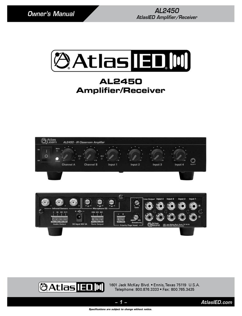
Atlas IED AA120G User manual

– 1 – AtlasIED.com
Specifications are subject to change without notice.
Owner’s Manual AA120G & AA240G
Commercial Mixer Amplifier
1601 Jack McKay Blvd. • Ennis,Texas 75119 U.S.A.
Telephone: 800.876.3333 • Fax: 800.765.3435
AA120G & AA240G
Commercial Mixer Amplifier

AtlasIED.com – 2 –
Specifications are subject to change without notice.
Owner’s Manual
AA120G & AA240G
Commercial Mixer Amplifier
1601 Jack McKay Blvd. • Ennis,Texas 75119 U.S.A.
Telephone: 800.876.3333 • Fax: 800.765.3435
Table of Contents
Important Safety Instructions.................................................................................................................. 3
Introduction ............................................................................................................................................ 8
Key Features........................................................................................................................................... 8
Applications ............................................................................................................................................ 8
Front Panel Description ........................................................................................................................... 9
Rear Panel Description ...........................................................................................................................10
Installation ............................................................................................................................................. 13
Rack Mounting ...................................................................................................................................... 14
Input Wire and Connections.................................................................................................................. 14
Output Wire and Connections............................................................................................................... 15
Operation............................................................................................................................................... 15
Measuring a Speaker System’s Impedance ......................................................................................... 16
Measuring 25V / 70.7V Distributed Speaker Systems .......................................................................... 16
Specifications .........................................................................................................................................17
Warranty ................................................................................................................................................ 20

– 3 – AtlasIED.com
Specifications are subject to change without notice.
Owner’s Manual AA120G & AA240G
Commercial Mixer Amplifier
1601 Jack McKay Blvd. • Ennis,Texas 75119 U.S.A.
Telephone: 800.876.3333 • Fax: 800.765.3435
Important Safety Instructions
1. Read these instructions.
2. Keep these instructions.
3. Pay close attention to all warnings.
4. Follow all instructions.
5. Do not use this device near liquids.
6. Clean only with a dry cloth.
7. Do not block any ventilation openings. Install in accordance with the manufacturer’s instructions.
8. Do not install near any heat sources such as radiators, heat registers, stoves, or other device (including amplifiers)
that produce heat.
9. Do not defeat the safety purpose of the polarized or grounding-type plug. A polarized plug has two blades with one wider than the
other. A grounding type plug has two blades and a third grounding prong. The wide blade or the third prong are provided for your
safety. If the provided plug does not fit into your outlet, consult an electrician for replacement of the obsolete outlet.
10. Protect the power cord from being walked on or pinched particularly at plugs, convenience receptacles, and the point where they
exit from the device.
11. Only use attachments/accessories specified by the manufacturer.
12. Use only with the cart, stand, tripod, bracket, or table specified by the manufacturer, or sold with the device. When a cart is used,
use caution when moving the cart/device combination to avoid injury from tip-over.
13. Unplug this device during lightning storms or when unused for long periods of time.
14. Refer all servicing to qualified service personnel. Servicing is required when the device has been damaged in any way, such as
power-supply cord or plug is damaged, liquid has been spilled, or objects have fallen into the device, the device has been exposed
to rain or moisture, does not operate normally, or has been dropped.
15. WARNING: To reduce the risk of fire or electric shock, do not expose this apparatus to rain or moisture.
16. The apparatus shall not be exposed to dripping or splashing and no objects filled with liquids, such as vases, shall be placed on apparatus.
1 7. The mains plug is used as a disconnect device. The mains plug of the apparatus should not be obstructed OR should be easily accessed
during intended use. To completely disconnect the power input, the mains plug of apparatus shall be disconnected from the mains.
18. This product shall be connected to a mains socket outlet with a protective earthing connection.
The lightning flash with arrowhead symbol within an
equilateral triangle, is intended to alert the user to the
presence of uninsulated “dangerous voltage “ within the
product’s enclosure that may be of sufficient magnitude
to constitute a risk of electric shock to persons.
The exclamation point within an equilateral triangle is
intended to alert the user to the presence of important
operating and maintenance (servicing) instructions in the
literature accompanying the product.

AtlasIED.com – 4 –
Specifications are subject to change without notice.
Owner’s Manual
AA120G & AA240G
Commercial Mixer Amplifier
1601 Jack McKay Blvd. • Ennis,Texas 75119 U.S.A.
Telephone: 800.876.3333 • Fax: 800.765.3435
WARNING - When The Device Is In Use
• WARNING: For the terminals marked with symbol of may be of sufficient magnitude to constitute a risk of electric shock. The
external wiring connected to the terminals requires installation by an instructed person or the use of ready-made leads or cords.
• WARNING: The apparatus shall not be exposed to dripping or splashing and that objects filled with liquids, such as vases, shall not be
placed on apparatus.
• WARNING: The mains plug is used as disconnect device, the disconnect device shall remain readily operable.
• To prevent electric shock, do not remove the product cover as there are high voltage components inside. Refer all servicing to
AtlasIED.
• Should any of the following irregularities occur during use, immediately switch off the power, disconnect the power cord from the
AC outlet and contact AtlasIED. Do not to attempt to continue operation with the product as this may cause fire or electric shock:
• Smoke or strange smell coming from the unit.
• If the product falls or the case is damaged.
• If water or any metallic objects falls into the product.
• If the power supply cord is damaged in any way.
• If the unit is malfunctioning.
• Do not insert or drop metallic objects or flammable materials into the ventilation holes of the product's cover, as this may result in
electric shock or fire.
• Do not place any containers with liquid or metallic objects on the top of the product. If any liquid spills into the unit, fire or electric
shock may result.
• Never operate this product or touch the power supply cord during an electrical storm, electric shock may result.
• Never exceed the power rating on the product when connecting equipment. Fire and/or property damage may result.
• Operate the product only with the voltage specified on the unit. Fire and/or electric shock may result if a higher voltage is used.
• Do not modify, kink, or cut the power cord. Do not place the power cord in close proximity to heaters and do not place heavy objects
on the power cord, including the product itself, doing so may result in fire or electrical shock.
• Ensure that the safety ground terminal is connected to a proper ground. Never connect the ground to a gas pipe as a catastrophic
disaster may result.
• Be sure the installation of the product is stable, avoid slanted surfaces as the product may fall and cause injury or property damage.
CAUTION - When Installing The Product
• Plugging in or unplugging the power cord with wet hands may result in electric shock.
• Never move the unit with the power cord plugged into the wall, as damage to the power cord may result.
• When unplugging the cord from the wall, grasp the plug, NOT the cord.
• Never install this product in humid or dusty locations, nor in direct sunlight, near sources of heat, or in areas where sooty smoke or
steam are present. Fire and electric shock may result.
• Keep all sides of the unit at least 31/2" away from objects that may obstruct air flow to prevent the unit's internal temperature rise.
CAUTION - When The Product Is In Use
• Never place heavy objects on the product, causing it to fall and/or break, resulting in personal injury and property damage. In
addition, the product itself may fall and cause injury and property damage.
• Contact AtlasIED for instructions on cleaning the inside of the unit. Large accumulations of dust inside the unit may result in heat
buildup and fire.
• Ensure that the power supply plug is securely plugged into the wall outlet. Never allow dust to accumulate on the power plug or
inside the wall outlet.
• When cleaning the unit or the unit is not to be operated for an extended period, unplug the power cord from the wall.

– 5 – AtlasIED.com
Specifications are subject to change without notice.
Owner’s Manual AA120G & AA240G
Commercial Mixer Amplifier
1601 Jack McKay Blvd. • Ennis,Texas 75119 U.S.A.
Telephone: 800.876.3333 • Fax: 800.765.3435
Instructions importantes de sécurité
1. Lisez ces instructions.
2. Conservez ces instructions.
3. Prêtez une attention particulière à tous les avertissements.
4. Observez toutes les instructions.
5. N’utilisez pas cet appareil à proximité de liquides.
6. Nettoyez uniquement avec un chiffon sec.
7. N’obstruez pas les ouvertures d’aération. Installez l’appareil conformément aux instructions du fabricant.
8. Installez l’appareil à l’écart de sources de chaleur, telles que radiateurs, bouches de chaleur, fours ou autres appareils (notamment
des amplificateurs) qui produisent de la chaleur.
9. Ne cherchez pas à modifier le dispositif de sécurité de la prise polarisée ou de mise à la masse. Une prise polarisée comporte deux
plots, l’un étant plus large que l’autre. Une prise avec mise à la masse se compose de deux plots et d’un troisième de mise à la
masse. La broche la plus large ou la troisième broche a été prévue pour la sécurité de l’utilisateur. Si la prise fournie ne s’insère pas
dans la prise murale, faites appel à un électricien pour qu’il remplace cette dernière qui est obsolète.
10. Protégez le cordon d’alimentation afin d’éviter qu’il soit piétiné ou pincé, en particulier au niveau des prises murales, plaques
multiprises et à la sortie de l’appareil.
11. N’utilisez que des périphériques et des accessoires spécifiés par le fabricant.
12. Ne l’utilisez que sur un chariot, support, trépied, console ou sur la table spécifiée par le fabricant ou vendue avec le produit. Avec un
chariot, déplacez l’ensemble appareil/chariot avec précaution pour éviter un accident provoqué par le basculement de l’appareil.
13. Débranchez l’appareil pendant les orages électriques ou s’il n’est pas utilisé pendant une longue durée.
14. Toutes les réparations doivent être réalisées par un personnel qualifié. L’appareil doit subir une maintenance s’il a été endommagé,
qu’il s’agisse de la détérioration du cordon d’alimentation ou de la prise secteur, du renversement de liquides ou d’objets tombés
dans l’appareil, d’une exposition à la pluie ou à l’eau, d’un fonctionnement anormal ou d’une chute.
15. AVERTISSEMENT : Afin de réduire le risque d’incendie et d’électrocution, n’exposez pas cet appareil à la pluie ou à l’humidité.
16. L’appareil ne doit pas être exposé à des éclaboussures ou à des gouttes d’eau et aucun objet rempli de liquide, tel qu’un vase, ne
doit être posé sur l’appareil.
17. La prise secteur est utilisée comme dispositif de déconnexion. La fiche secteur de l’appareil ne doit pas être obstruée ou doit être
facilement accessible pendant l’utilisation prévue. Pour débrancher complètement l’entrée de courant, la fiche secteur de l’appareil
doit être débranchée du secteur.
18. Ce produit doit être connecté à une prise de courant secteur disposant d’une protection de mise à la masse.
Le symbole d’un éclair à l’intérieur d’un triangle équilatéral
est destiné à alerter l’utilisateur de la présence d’une
tension dangereuse non isolée à l’intérieur du produit
dont la puissance est suffisante pour présenter un risque
d’électrocution.
Le point d’exclamation à l’intérieur d’un triangle
équilatéral est destiné à alerter l’utilisateur de la présence
d’instructions importantes sur le fonctionnement et sur
la maintenance dans la documentation accompagnant
l’appareil.
PRUDENCE
PRUDENCE
AVERTISSEMENT
AFIN D’ÉVITER UN INCENDIE OU UNE ÉLECTROCUTION,
CET APPAREIL NE DOIT PAS ÊTRE EXPOSÉ À L’HUMIDITÉ OU À L’EAU.

AtlasIED.com – 6 –
Specifications are subject to change without notice.
Owner’s Manual
AA120G & AA240G
Commercial Mixer Amplifier
1601 Jack McKay Blvd. • Ennis,Texas 75119 U.S.A.
Telephone: 800.876.3333 • Fax: 800.765.3435
AVERTISSEMENT - Lorsque l’appareil est en utilisation
• AVERTISSEMENT : Pour les bornes marquées avec le symbole d’une magnitude pouvant être suffisante pour constituer un risque
de choc électrique. Le câblage externe connecté aux bornes nécessite une installation par un personnel dûment formé, ou
l’utilisation de câbles ou de cordons prêts à l’emploi.
• AVERTISSEMENT : L’appareil ne doit pas être exposé à des gouttes ou des éclaboussures et les objets remplis de liquides, comme
les vases, ne doivent pas être posés dessus.
• AVERTISSEMENT : La prise secteur est utilisée comme dispositif de déconnexion ; ce dispositif de déconnexion doit demeurer
immédiatement utilisable.
• Pour éviter une électrocution, ne démontez pas le couvercle du produit, en effet des composants à haute tension se trouvent à
l’intérieur. Toutes les maintenances doivent être réalisées par AtlasIED.
• Si l’une des irrégularités suivantes se produit pendant l’utilisation, coupez immédiatement l’alimentation électrique, débranchez le
cordon d’alimentation de la prise secteur et contactez AtlasIED. N’essayez pas de poursuivre l’utilisation de ce produit, en effet il
pourrait en résulter un incendie ou une électrocution :
• Fumée ou odeur étrange provenant de l’appareil.
• Si le produit tombe ou si l’enceinte est endommagée.
• Si de l’eau ou des objets métalliques tombent dans le produit.
• Si le cordon d’alimentation est endommagé, quelle qu’en soit la manière.
• Si l’appareil ne fonctionne pas correctement.
• N’insérez ni ne déposez d’objets métalliques ou de matériaux inflammables dans les orifices de ventilation de l’enceinte du produit,
ce qui pourrait être à l’origine d’une électrocution ou d’un incendie.
• Ne placez aucun récipient contenant des liquides ou des objets métalliques sur le produit. Si des liquides se répandent dans
l’appareil, un incendie ou une électrocution pourrait se produire.
• N’utilisez jamais ce produit ni n’entrez en contact avec le cordon d’alimentation pendant un orage, vous pourriez être électrocuté.
• Ne dépassez jamais la puissance nominale du produit lors de la connexion de l’appareil. Un incendie et/ou des dommages matériels
pourraient en résulter.
• Ne faites fonctionner le produit qu’avec la tension spécifiée sur l’appareil. Un incendie et/ou une électrocution peuvent se produire si
une tension plus élevée est utilisée.
• Le cordon d’alimentation ne doit être ni modifié, entortillé ou coupé. Ne placez pas le cordon d’alimentation à proximité de
radiateurs et ne déposez aucun objet lourd sur le cordon d’alimentation, notamment le produit lui-même, ce qui pourrait provoquer
un incendie ou une électrocution.
• Assurez-vous que la borne de masse de sécurité est connectée à une masse appropriée. Ne connectez jamais la masse à un tuyau
de gaz, un désastre catastrophique pourrait s’ensuivre.
• Assurez-vous que l’installation du produit est stable, évitez les surfaces inclinées pouvant entraîner la chute du produit et provoquer
un accident ou des dommages matériels.
PRUDENCE - Lors de l’installation du produit
• Le branchement ou le débranchement du cordon d’alimentation avec des mains mouillées peut être à l’origine d’une électrocution.
• Ne déplacez jamais l’appareil avec le cordon d’alimentation branché dans la prise murale, en effet ceci pourrait endommager le
cordon d’alimentation.
• Lorsque vous débranchez le cordon de la prise murale, saisissez la prise et NON le cordon.
• N’installez jamais ce produit dans des endroits humides ou poussiéreux, ni en plein soleil ou près de sources de chaleur, ou dans
des emplacements avec de la fumée et de la suie ou encore avec de la vapeur. Un incendie et une électrocution peuvent se
produire.
• Les quatre côtés de l’appareil doivent bénéficier d’un espace minimum de 9 cm (3,5 po) avec des objets pouvant obstruer le débit
d’air et favoriser l’élévation de la température à l’intérieur de l’appareil.
– 7 – AtlasIED.com
Specifications are subject to change without notice.
Owner’s Manual AA120G & AA240G
Commercial Mixer Amplifier
1601 Jack McKay Blvd. • Ennis,Texas 75119 U.S.A.
Telephone: 800.876.3333 • Fax: 800.765.3435
PRUDENCE - Lorsque le produit est en utilisation
• Ne placez jamais d’objets lourds sur le produit, pouvant induire une chute et/ou une rupture, entraînant un accident et des
dommages matériels. En outre, le produit lui-même peut tomber et provoquer un accident et des dommages matériels.
• Contactez AtlasIED pour des instructions sur le nettoyage de l’intérieur de l’appareil. D’importantes accumulations de poussières à
l’intérieur de l’appareil peuvent entraîner une accumulation de chaleur et un incendie.
• Assurez-vous que la prise d’alimentation est bien branchée dans la prise murale. Ne laissez jamais la poussière s’accumuler sur la
prise d’alimentation ou sous la plaque murale.
• Lorsque vous nettoyez l’appareil ou que celui-ci ne doit pas être utilisé sur une durée prolongée, débranchez le cordon d’alimentation
du mur.

AtlasIED.com – 8 –
Specifications are subject to change without notice.
Owner’s Manual
AA120G & AA240G
Commercial Mixer Amplifier
1601 Jack McKay Blvd. • Ennis,Texas 75119 U.S.A.
Telephone: 800.876.3333 • Fax: 800.765.3435
Introduction
Congratulations and thank you for purchasing the AtlasIED AA120G / AA240G mixer amplifier. Engineered for reliability, the AtlasIED
AA120G / AA240G will provide years of service and flexibility in background music and paging applications.
Key Features
• Zone 1 Output 120W (AA120G), 240W (AA240G), 4Ω, 25V, 70V, 100V
• Zone 2 Output 1W@ 8Ωor 1.5V@ 600Ω
• Inputs 1-4 mic / balanced line switchable
• Input 5 & 6 RCA summed, Input 4 3.5mm summed and parallel with Input 4
• Input signal indicator, Master peak and signal indicator
• Bass and treble control
• Input 1 has VOX send
• Inputs 2-6 have switch selectable mute receive via VOX or contact closure
• Remote level control selectable Input 6 or Master
• Pre-output balanced
• Amp In insert for external processing
• Switch selectable Bridge In/Out bus allows amplifier combining
• Hi cut filter for paging horns
• Zone 2 Output, 1W & Line
• Global Switch Mode AC Power Supply for use in any 120V to 240V country
Applications
The AtlasIED AA120G / AA240G are the perfect choice for distributed business paging and background music (BGM) systems, small to
medium speech privacy systems, and in applications where music on hold (MOH) plus paging is required.

– 9 – AtlasIED.com
Specifications are subject to change without notice.
Owner’s Manual AA120G & AA240G
Commercial Mixer Amplifier
1601 Jack McKay Blvd. • Ennis,Texas 75119 U.S.A.
Telephone: 800.876.3333 • Fax: 800.765.3435
Front Panel
1. Input Signal Presence/Clip Indicators
Green LED, one above each channel’s volume control, illuminates when input signal exceeds –40 dBu, and flashes brightly at threshold
of audible distortion.
2. Master Level Control
The Master Level control will raise or lower all the input channels together. A good starting point for setting gain structure is to set
the Master Level control at the 12:00 position, and then adjust the individual channels one at a time.
3. Output Signal Indicator
Green LED above master level control illuminates when any input signal exceeds –40 dBu.
4. Output Peak Indicator
Red LED above master output volume control will illuminate when the amp is -3dB below a clipping condition. This is caused by
excessively high input levels or when a Gain control is turned up too high. An occasional flash is OK.
5. Power Indicator
This LED illuminates Blue when the power switch is turned On.
6. Input Level Controls
The rotary control varies the amplitude of the signal fed to the amplifier input. Turn clockwise to increase and counter-clockwise to
decrease the signal level.
7. Tone Controls
Bass and Treble nondetented recessed potentiometers under master level control.
Bass ±10 dB at 100 Hz, Treble ±10 dB at 10 kHz.
8. Power Switch
This push switch (On/Off) supplies power to the mixer amplifier.
1 2
6
3 4 5
7 8

AtlasIED.com – 10 –
Specifications are subject to change without notice.
Owner’s Manual
AA120G & AA240G
Commercial Mixer Amplifier
1601 Jack McKay Blvd. • Ennis,Texas 75119 U.S.A.
Telephone: 800.876.3333 • Fax: 800.765.3435
Rear Panel
1. AC Power Inlet
Detachable IEC accepts US or Euro style power cords.
2. Amplifier Outputs
For loudspeaker connections, connect as follows or proceed to the setup section for typical wiring schemes.
• COM - Loudspeaker common or negative connection
• 8Ω- Connect to positive terminal on direct coupled loudspeakers
• 25V - Connect to positive terminal on transformer coupled loudspeakers
• 70V - Connect to positive terminal on transformer coupled loudspeakers
• 100V - Connect to positive terminal on transformer coupled loudspeakers
3. Inputs 1-4 Euro block Connectors
Balanced Microphone or Line level signals connect to the (+), (–), and (G) terminals. To select between Mic or Line input levels, refer to
the Switch A chart on the rear of the amplifier for feature assignment. If connecting an unbalanced line level input, tie (short) the (G) and
(–) terminals together for negative or ground connection and the positive or (+) signal to the (+) terminal on the amplifier input. If the
input is used in Mic mode, Phantom power for condenser type microphones is available in the DIP switch settings on the rear panel.
4. Switch A Settings
• DP SW #1 - When in the On (UP) position Input 4 is in Mic mode, OFF (DOWN) position Input 4 is in Line mode.
• DP SW #2 - When in the On (UP) position Input 3 is in Mic mode, OFF (DOWN) position Input 3 is in Line mode.
• DP SW #3 - When in the On (UP) position Input 2 is in Mic mode, OFF (DOWN) position Input 2 is in Line mode.
• DP SW #4 - When in the On (UP) position Input 1 is in Mic mode, OFF (DOWN) position Input 1 is in Line mode.
• DP SW #5 - When in the On (UP) position Input 4 Phantom power is present at the + & - terminals
• DP SW #6 - When in the On (UP) position Input 3 Phantom power is present at the + & - terminals
• DP SW #7 - When in the On (UP) position Input 2 Phantom power is present at the + & - terminals
• DP SW #8 - When in the On (UP) position Input 1 Phantom power is present at the + & - terminals
481012 1113 15 1614 5
1 2 79 63
1
Input 4
Mic
Line
2
Input 3
Mic
Line
3
Input 2
Mic
Line
4
Input 1
Mic
Line
5
Input 4
On
Off
6
Input 3
On
Off
7
Input 2
On
Off
Phantom
8
Input 1
On
Off
Switch A

– 11 – AtlasIED.com
Specifications are subject to change without notice.
Owner’s Manual AA120G & AA240G
Commercial Mixer Amplifier
1601 Jack McKay Blvd. • Ennis,Texas 75119 U.S.A.
Telephone: 800.876.3333 • Fax: 800.765.3435
Rear Panel
5. Mic Trim
This variable control allows fine tuning of the gain of Inputs 1-4. There is 20dB of variable gain available. The trim only
applies when the input is set to the “Mic” position on the DIP switch.
6. Input 1 VOX Threshold Adjustment
Input 1 signal can be used to trigger or activate a mute command. When an input is set to Mute Receive via Switch B Input Mute Rec
section, the input associated to the switch will be muted when a signal is applied to Input 1 or when the Remote mute terminals are
shorted together (See Remote Mute). The VOX Mute Sensitivity Control adjusts how sensitive the mute circuitry from Input 1 reacts.
Rotating the VOX Sensitivity clockwise (CW) will lower the sensitivity, where a higher amplitude signal from Input 1 will be required to
trigger the mute send circuits. Fully Counter Clockwise (FCCW) will raise the sensitivity of the mute circuits, where a lower amplitude
signal from Input 1 is required to trigger a mute send. VOX Sensitivity trim range is from Off (FCW), On / Low 1.25mV to High 9FCCW)
40uV. Calibration of this control in conjunction with the microphone to be used is very important to assure the proper amount of signal
from the mic is enough to trigger the mute circuits. If it is not calibrated properly, the mute may not be triggered when a weak voice vs
a strong voice uses the mic.
7. Input 4 (Dual Function)
Input 4 can accept more than one type of audio signal. This input section has a 3 position Phoenix connector for Mic or Line input
signals and a 3.5mm stereo jack that is summed. The level to the amplifier mix is controlled by Input 4 level located on the front panel.
Note: Only one type of input signal can be applied at one time.
A. Balanced Mic / Line - Balanced Microphone or Line level signals connect to the (+), (–), and (G) terminals. To select between Mic or
Line input levels, refer to the DIP switch chart on the rear of the amplifier for feature assignment. If connecting an unbalanced line level
input, tie (short) the (G) and (–) terminals together for negative or ground connection and the positive or (+) signal to the (+) terminal
on the amplifier input. If the input is used in Mic mode, Phantom power for condenser type microphones is available in the DIP switch
settings on the rear panel.
B. Input 4 Stereo Summed - Input 4 consists of stereo 3.5mm summing inputs, suitable for connection to the output of iPod®, CD/DVD
players, etc.
8. Switch B Functions
• DP SW #1 - Input 6, this the input sensitivity selection between 100mV and 300mV. When selected to 100mV it will take less signal
from the audio source to achieve max output.
• DP SW #2 - VCA switch assigns what is Inputs are going to remotely controlled when a 10k ohm potentiometer is connect across
the two VCA (Voltage Control Amplifier) ports. There are two selections a for remote level control, Input 6 (music) or the overall amp
Master Level.
• DP SW #3 - Low Cut switch when assigned to On (UP) activates a Low Cut Filter reducing signal from 300Hz 6dB per octave and
below. Note: The Bass control on the front panel is active. This is ideal to use with paging horns.
• DP SW #4 - Input 6 Mute Receive, When the DPA SW is placed in the On (UP) position the input can be muted via the Remote
Mute port or via a VOX trigger.
• DP SW #5 - Input 5 Mute Receive, When the DPA SW is placed in the On (UP) position the input can be muted via the Remote
Mute port or via a VOX trigger.
• DP SW #6 - Input 4 Mute Receive, When the DPA SW is placed in the On (UP) position the input can be muted via the Remote
Mute port or via a VOX trigger.
• DP SW #7 - Input 3 Mute Receive, When the DPA SW is placed in the On (UP) position the input can be muted via the Remote
Mute port or via a VOX trigger.
• DP SW #8 - Input 2 Mute Receive, When the DPA SW is placed in the On (UP) position the input can be muted via the Remote
Mute port or via a VOX trigger.
1
Input 6
Sens
100mV
300mV
2
VCA
Input 6
Master
3
Low Cut
On
Off
4
Input 6
On
Off
5
Input 5
On
Off
6
Input 4
Mute Rec
On
Off
7
Input 3
On
Off
8
Input 2
On
Off
Switch B

AtlasIED.com – 12 –
Specifications are subject to change without notice.
Owner’s Manual
AA120G & AA240G
Commercial Mixer Amplifier
1601 Jack McKay Blvd. • Ennis,Texas 75119 U.S.A.
Telephone: 800.876.3333 • Fax: 800.765.3435
Rear Panel
9. Inputs 5 & 6
Inputs 5 & 6 consist of a pair of stereo summing, line level inputs. Connect unbalanced audio outputs here such as CD
players or audio from DVD players. Input 5 has a fix Input Sensitivity of 300mV. Input 6 has a selectable sensitivity via a
Dip Switch #1 on Switch B.
10. Remote Mute
Shorting the Remote Mute terminals will mute the inputs that are assigned in Switch B to receive the mute command. When an input
is set to Mute Receive via the corresponding DIP switch, the input associated to the switch will be muted when Mute terminals are
shorted together. This connection is usually done via remote switch on a microphone. Note: Input 1 cannot be muted.
11. Remote Level Control
Remote location of the level control can be accomplished via the VCA control port and a 10K potentiometer. You can control the overall
level (Master) or just Input 6 (Music). It is very common to only adjust the music level in a system. Paging levels rarely need to change.
This selection is made on Switch “B”, via DP SW #2 VCA. Connect the two leads from the optional remote volume control to these
terminals. We recommend using a AtlasIED AAVC-10K or a WPD-VC10K part. If not any 10KΩpot will work.
Remote Level set up - set the system’s maximum levels using the amplifier level controls and then use the remote VCA potentiometer
as an attenuator from the maximum levels set. See the VCA setup illustration for instructions on wiring the potentiometer. Note: The
remote level control is POST (after) the Master and Input 6 Level Controls. VCA wiring will depend on the wiring of the potentiometer.
You may need to reverse the wires on the VCA port to achieve the level control rotation direction.
12. Zone 2 Output
Zone 2 Outputs are used to feed a secondary zone such as lobby, restrooms, bar or outside area’s. There are two types of outputs
needed to meet the design requirements. A 600Ωline out is provided to feed a telephone Music ON Hold application or to feed a
second amplifier that can power multiple speakers. The second option is an amplified output to power a signal speaker. Each input has
a selection switch to assign it to the Zone 2 Output. When selected the input will feed both the 1W amplified output and the 600Ωline
output. Note: When an input is routed to the Zone 2 Output via Switch C, it is PRE (before) the input channel level, Master level and the
remote level. It is important to set your source gains to achieve the desired Zone 2 level and the main system level of Zone 1.
• Zone 2 Output – 600Ω
The 600Ω1.5V max (Zone 2 Out) output is typically connected to a PBX MUSIC ON HOLD port, also known as MOH. Can also be
connected to a second amplifier input.
• Zone 2 Output – 1 Watt 8Ω
The 8Ω1W Zone 2 output can drive an external 8Ωspeaker.
• Zone 2 Level Control
Potentiometer adjusts level for both Zone 2 outputs.
1
Input 6
On
Off
2
Input 5
On
Off
3
Input 4
On
Off
4
Input 3
On
Off
5
Input 2
On
Off
6
Input 1
On
Off
To VCA Terminals
Switch C

– 13 – AtlasIED.com
Specifications are subject to change without notice.
Owner’s Manual AA120G & AA240G
Commercial Mixer Amplifier
1601 Jack McKay Blvd. • Ennis,Texas 75119 U.S.A.
Telephone: 800.876.3333 • Fax: 800.765.3435
Rear Panel
13. Pre-Out
The Pre-Out is a 3-Pin Balanced Euroblock connector. Line level output is Pre-Master Level. The input level potentiometers control the
amount of output signal at the Pre-Out ports. Use this output to connect signal to a secondary amplifier. Note: When the Remote
Level when set to Input 6, the Pre-Out level will also be adjusted for Input 6. The Pre Out will not be affected when the Remote Level
Control is set to Master.
14. Amp In
The Amp Input port can be used to insert an external signal processor such as EQ, limiter. When using the Amp In feature, the Amp
Direct In switch needs to be in the “On” position.
15. Bridge In/Out
Certain installations have the need to combine one or more powered mixers buss’s together. These mixers may be in different rooms
of an install but have the need to share a page or music content throughout the installation. These terminals provide a way to send
and receive balanced line level signals from the internal mix bus of a AA120G or AA240G. The “BRIDGE IN/OUT” feature is PRE Tone
Controls and Low Cut Filter the Bridge In/Out feature allows you to send and receive a balanced signal. This is important for allowing
longer distances between the mixers. Note: This function should ONLY be used with other Atlas Sound mixers that have this feature.
The Send and Receive signals are combined through the same terminals.
16. Bridge Select Port
The “Bridge Select (Sel)” terminals are the access point to activate the “Bridge In/Out” feature. To activate the feature connect the two
points together via an external contact closure. These two points must be connected to send or receive any signal. By connecting the
Bridge In/Out terminals of two AA240s, a simple room combining system can be accomplished. If using a remote switch and closing
it, the “Bridge Select (Sel)” will combine the amps as one, opening the switch will separate the two amps. Note: If combining 3 or 4
mixers together the output level will have to be adjusted before and after Bridge Sel terminals are connected (shorted) together. We
suggest utilizing the Remote Level control when using this feature.
Installation
CAUTION: Ensure the mixer amplifier is disconnected from the power source, with power switch in the “Off” position and all level
controls turned completely counterclockwise before beginning installation.
Use a standard 19" (483mm) equipment rack with an optional rack-mount kit. See below for dimensions.
You may also stack mixer amplifiers without using a cabinet or you may place a single mixer amplifier on a surface with 12" of air space
around the unit for convection cooling.
NOTE: When transporting in a rack, mixer amplifiers should be supported at the front and back.
When using an equipment rack, do not mount units directly on top of each other. Allow 2 rack units (3.5") between units for convection
cooling. The side walls of the rack should be a minimum of 2" (51mm) away from the mixer amplifier sides and the back of the rack
should be a minimum of 4" (102mm) from the mixer amplifier back panel.
Amp 1 (AA120G or AA240G) Amp 2 (AA120G or AA240G)

AtlasIED.com – 14 –
Specifications are subject to change without notice.
Owner’s Manual
AA120G & AA240G
Commercial Mixer Amplifier
1601 Jack McKay Blvd. • Ennis,Texas 75119 U.S.A.
Telephone: 800.876.3333 • Fax: 800.765.3435
Rack Mounting (Optional)
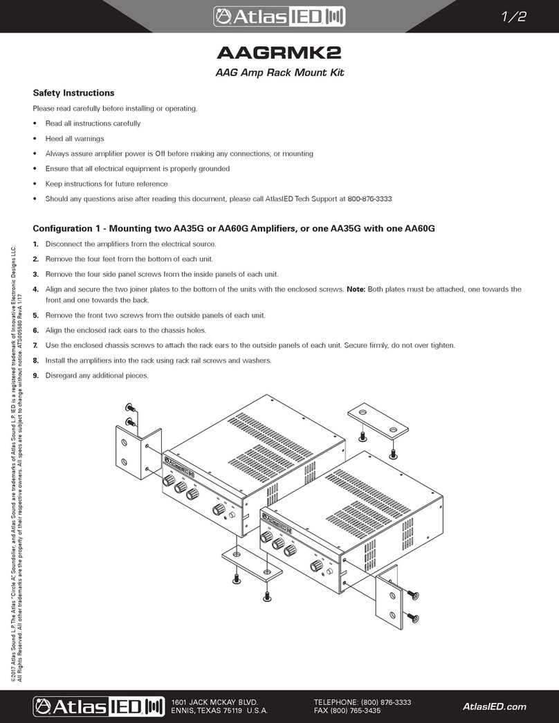
The AA120G & AA240G features an optional 19" rack mount kit. This kit is the AAGRMK1. Note: The AAGRMK1 kit only works with AAG
Series mixer amplifiers, and will not work with AA Series or AAPHD Series mixer amplifiers. The AARMK2-0 kit will not work with AAG
Series mixer amplifiers.
Choose Input Wire and Connectors
AtlasIED recommends using balanced line (two-conductor plus shield), 22-24 gauge cables and connectors. Unbalanced line may also
be used but may result in noise over long cable runs.
The AA120G and AA240G have two types of input connectors, Euroblock and RCA.
• Mic / Line Connector - Euroblock 3.5mm pitch spacing
• RCA Input Connector - For stereo music signals, unbalanced, summed together, two connectors per input. Input 4 uses 3.5mm
stereo.
Figure 2.4
Dual RCA Input Connector
Figure 2.3
Mic/Line Connector
To Mic or
Line-Level Source
To Stereo
Line-Level Source

– 15 – AtlasIED.com
Specifications are subject to change without notice.
Owner’s Manual AA120G & AA240G
Commercial Mixer Amplifier
1601 Jack McKay Blvd. • Ennis,Texas 75119 U.S.A.
Telephone: 800.876.3333 • Fax: 800.765.3435
Choose Output Wire and Connectors
Amplifier Output Connections: Slip the cable lugs under the output screw terminals and tighten. Slide the supplied non-touch cover
over the output connections from top to bottom to cover them. AtlasIED recommends using high-quality, two-conductor, heavy gauge
speaker wire and connectors. Crimp-on spade lugs may be used for the output connectors. To prevent the possibility of short-circuits,
wrap or otherwise insulate exposed loudspeaker cable connectors. Cover the output connections with the supplied clear non-touch
cover by sliding the cover on.
Note: Custom wiring should only be performed by qualified personnel. Class 2 wiring is required.
Caution: Never use shielded cable for speaker wiring.
Outputs
Maintain proper polarity (+/–) on amplifier output connectors. Connect the Amplifier Output screw terminals to the loudspeaker loads.
Use terminals marked COM and 70V or 100V for constant voltage loudspeaker loads. Use terminals marked COM and 4Ωfor either a
4Ωor 8Ωspeaker load. Note: The amplifier power output is 50% of the 4Ωpower output. Connect the COM terminal to loudspeaker
negative (–) lead; connect one of the other terminals to loudspeaker positive (+) lead. Cover the output connections with the supplied
clear non-touch cover by sliding the cover on.
Operation
Powering Up
1. Turn Off any equipment connected to the Preamp Output connector.
2. Plug the amplifier’s power cord into a 3-wire grounded AC outlet.
3. Turn down the input volume controls.
4. Turn down the master volume control.
5. Turn on the Power switch. The Power indicator should glow.
6. Turn the input volume controls in use about 3/4up.
7. Turn up the master volume control(s) until the desired loudness or power level is achieved.
8. Touch up the input levels as needed for music and voice.
9. Turn on any equipment connected to the Preamp Output connector.
10. Disconnect the power cord before making any wiring or installation changes.
Amplifier Output
Connections

AtlasIED.com – 16 –
Specifications are subject to change without notice.
Owner’s Manual
AA120G & AA240G
Commercial Mixer Amplifier
1601 Jack McKay Blvd. • Ennis,Texas 75119 U.S.A.
Telephone: 800.876.3333 • Fax: 800.765.3435
Measuring a Speaker System’s Impedance
Note: It is important to only use an Audio Impedance Meter and not a conventional volt/Ωmeter. A true audio frequency impedance
meter is essential for reliable installation of background music and paging systems in residences, offices buildings, and public areas.
Avoid costly service calls and amplifier damage by verifying actual speaker system impedance prior to operation. Unlike conventional
volt/Ωmeters, which measure DC resistance, an Audio Impedance Meter unit utilizes an internal frequency oscillator to measure
true impedance. It may also be utilized with 25V/70.7V and 100V speaker line transformers, L-pads and matching impedance volume
controls. There are several Audio Impedance meters on the market, if you need to buy one we suggest going to MCM Electronics or
search the internet for Audio Impedance Meter.
Measuring 25V/70.7V Distributed Speaker Systems
Large distributed systems typically utilize 25.2V or 70.7V transformers (50V and 100V in Europe), to greatly ease the connection of
multiple speakers and facilitate long cable runs. These speakers are connected in parallel, as shown below, with total wattage ratings
added to calculate the overall rating of the system. Connecting this meter to a speaker arrangement such as this will provide the overall
impedance of the system. Using the following formula, you can calculate the wattage. Simply put, when connected to a distributed
system, take the voltage of the system (normally 70.7V or 25.2V), squared, divided by the impedance displayed on the meter. Your
answer will be the total system wattage. This total wattage must not exceed the wattage output rating of the amplifier or damage
may occur. In this example the measurement for a 70.7V design with speakers of 10W, 30W and 60W, the system impedance would
measure close to 50Ω. Formula 70.7V x 70.7V = 4998, 4998 / 100W = 49.9Ω. If this speaker system load is connected to at least a
120W amp @ 70.7V, the system will operate properly. Note: It is always recommended to use a larger amp than needed with output
power headroom of at least 25%.
Max Load Chart
Speaker Tap AA120G AA240G
4Ω4Ω4Ω
25V 5.25Ω2.6Ω
70.7V 41Ω20Ω
100V 83Ω41Ω

– 17 – AtlasIED.com
Specifications are subject to change without notice.
Owner’s Manual AA120G & AA240G
Commercial Mixer Amplifier
1601 Jack McKay Blvd. • Ennis,Texas 75119 U.S.A.
Telephone: 800.876.3333 • Fax: 800.765.3435
System AA120G AA240G
Type Professional Mixer Amplifier
Electrical AA120G AA240G
Power into 4Ωor 25V/70V/100V Output
(1kHz with 0.5% THD)
120W 240W
Frequency Response (at 1 Watt from 4ΩTap) 50Hz - 15kHz ±3 dB
Front Panel AA120G AA240G
Power Switch Push Type
Indicators Input Signal, Master Level Signal, Peak, Power
Level Controls Master, Inputs 1 - 6
Tone Controls Bass ±10dB @ 100Hz
Treble ±10dB @ 10kHz
Rear Panel AA120G AA240G
Inputs Ports Mic / Line Balanced Qty 4, 3 Position PHX Type. 3.5mm Pitch
Auxiliary Unbalanced Qty 2, RCA
Auxiliary Unbalanced Qty 1, 3.5mm (In Parallel with Input 4)
Input 1 - 4 Trim Rotary Pot, Functions in Mic Mode Only
Amp In Unbalanced, 400mV to Achieve Full Output, 5 Position Phoenix (Shared with Pre Out)
Pre Out Balanced, 1.5V Max Output, Pre Master Level, 5 Position Phoenix (Shared with Amp In)
VOX Sensitivity Pot Range Off, Low (1.25mV) Variable to High (40uV)
Remote Mute Remote Control Contact Closure, 2 Position Phoenix, 3.5mm Pitch
Zone 2 Output Level Potentiometer, Pre-Master Level & Pre-Remote Master Level
Zone 2 Output 1W @ 8Ω2 Position Phoenix, 3.5mm Pitch
Zone 2 Output 600Ω1.5V Max, 2 Position Phoenix, 3.5mm Pitch
Zone 2 Switch C 6 Position Dip Switch, Inputs 1-6 Zone 2 Assignment
Remote Level VCA (Voltage Control Amplifier) Remote Control via 10K Pot, 2 Position Phoenix, 3.5mm Pitch
Remote Level Input Assignments Master Level or Input 6 selection via Switch B Settings
Bridge In/Out Input & Output Port Balanced 3 Position Phoenix, 3.5mm Pitch
Bridge In/Out Sel (Select) Port 2 Position Phoenix, 3.5mm Pitch, Shorted for Bridge ON
Bridge In/Out Distance <200ft
Input Configure Switch A Functions 8 Position Dip Switch
DP SW 1,2,3,4 Inputs 1-4 Mic or Line Select
DP SW 5,6,7,8 Inputs 1-4 Phantom Power On or Off
Input Configure Switch B Functions 8 Position Dip Switch
DP SW 1, Input 6 Input Sensitivity Select 100mV or 300mV
DP SW 2, Remote Level Control Select Input 6 or Master
DP SW 3,4,5,6 Inputs 2-6 Mute Receive Select
Input Configure Switch C Functions 6 Position Dip Switch
DP SW 1,2,3,4,5,6 Input 1-6 6 Zone 2 Assign Select

AtlasIED.com – 18 –
Specifications are subject to change without notice.
Owner’s Manual
AA120G & AA240G
Commercial Mixer Amplifier
1601 Jack McKay Blvd. • Ennis,Texas 75119 U.S.A.
Telephone: 800.876.3333 • Fax: 800.765.3435
Technical AA120G AA240G
Signal to Noise Ratio (Ref. to Rated Power,
Master Volume at Minimum)
Mic: > 55 dB
Line: > 55 dB
Telephone: > 55 dB
AUX Input 4, 5, 6: > 75 dB
THD + N < 0.5% at Rated Power at 1kHz
Input Sensitivity
(for Full Output at Maximum Gain)
Input 1, 2, 3, 4 Mic Mode: 3mV
9Input 1, 2, 3, 4 Line Mode: 400mV
Input 4 3.5mm Summed: 400mV
Input 5, 6 RCA Unbalanced Summed: 316mV (-10dBV)
Input Impedance (Nominal) Input 1, 2, 3, 4 Mic Mode: 1.2kΩ
Input 1, 2, 3, 4 Line Mode: 1.2kΩ
Input 4 3.5mm Summed: 10kΩ
Input 5, 6 RCA Unbalanced Summed: 10kΩ
Crosstalk (Below Rated Power) –82 dB at 1kHz
Line Output Level 1V, Signal is Pre Master Level Control
Phantom Power 24VDC
Power Requirements AA120G AA240G
AC Mains 120V - 240V 50/60Hz
AC Cord IEC to NEMA 5-20P, 2M, 18 Gauge
Idle Power Consumption 0.35A, 24W, 81 BTU 0.36A, 25W, 85 BTU
Average Power Consumption 1/3Rated Output 1.56A, 280W, 955 BTU 2.9A, 348W, 1187 BTU
Max Power Consumption 2.35A, 420W, 1433 BTI 4.5A, 540W, 1842 BTI
AC Line Operating Range Universal Power Supply, 100V - 240V 50 / 60 Hz
Operating Temperature / Humidity 0° C to 40° C at 95% Relative Humidity (Non-Condensing)
Cooling Fan Cooled
Mechanical AA120G AA240G
Chassis Steel
Finish Black Paint
RoHS Compliant Ye s
Safety Listings ETL (UL 60065 Standard), CE
Dimensions and Weight AA120G AA240G
Dimensions 17" W x 3.50" H x 9.5" D (431mm x 90mm x 241mm)
17" W x 4" H x 11" D (431mm x 102mm x 279mm) (Including Feet and Knobs)
Net Weight 13.5 lbs (6.12kg) 16.5 lbs (7.5kg)
Shipping Weight 16.4 lbs (7.4 kg) 19.5 lbs (8.8 kg)

– 19 – AtlasIED.com
Specifications are subject to change without notice.
Owner’s Manual AA120G & AA240G
Commercial Mixer Amplifier
1601 Jack McKay Blvd. • Ennis,Texas 75119 U.S.A.
Telephone: 800.876.3333 • Fax: 800.765.3435
Notes:

AtlasIED.com – 20 –
Specifications are subject to change without notice.
Owner’s Manual
AA120G & AA240G
Commercial Mixer Amplifier
1601 Jack McKay Blvd. • Ennis,Texas 75119 U.S.A.
Telephone: 800.876.3333 • Fax: 800.765.3435
Limited Warranty
All products manufactured by AtlasIED are warranted to the original dealer/installer, industrial or commercial purchaser to be free from
defects in material and workmanship and to be in compliance with our published specifications, if any. This warranty shall extend from
the date of purchase for a period of three years on all AtlasIED products, including SOUNDOLIER brand, and ATLAS SOUND brand
products except as follows: one year on electronics and control systems; one year on replacement parts; and one year on Musician
Series stands and related accessories. Additionally, fuses and lamps carry no warranty. AtlasIED will solely at its discretion, replace
at no charge or repair free of charge defective parts or products when the product has been applied and used in accordance with our
published operation and installation instructions. We will not be responsible for defects caused by improper storage, misuse (including
failure to provide reasonable and necessary maintenance), accident, abnormal atmospheres, water immersion, lightning discharge,
or malfunctions when products have been modified or operated in excess of rated power, altered, serviced or installed in other than
a workman like manner. The original sales invoice should be retained as evidence of purchase under the terms of this warranty. All
warranty returns must comply with our returns policy set forth below. When products returned to AtlasIED do not qualify for repair
or replacement under our warranty, repairs may be performed at prevailing costs for material and labor unless there is included with
the returned product(s) a written request for an estimate of repair costs before any nonwarranty work is performed. In the event of
replacement or upon completion of repairs, return shipment will be made with the transportation charges collect.
EXCEPT TO THE EXTENT THAT APPLICABLE LAW PREVENTS THE LIMITATION OF CONSEQUENTIAL DAMAGES FOR PERSONAL
INJURY, ATLASIED SHALL NOT BE LIABLE IN TORT OR CONTRACT FOR ANY DIRECT, CONSEQUENTIAL OR INCIDENTAL LOSS
OR DAMAGE ARISING OUT OF THE INSTALLATION, USE OR INABILITY TO USE THE PRODUCTS. THE ABOVE WARRANTY IS IN
LIEU OF ALL OTHER WARRANTIES INCLUDING BUT NOT LIMITED TO WARRANTIES OF MERCHANTABILITY AND FITNESS FOR A
PARTICULAR PURPOSE.
AtlasIED does not assume, or does it authorize any other person to assume or extend on its behalf, any other warranty, obligation, or
liability. This warranty gives you specific legal rights and you may have other rights which vary from state to state.
Service
Should your amplifier require service, please contact the AtlasIED warranty department at
1-877-689-8055, ext. 277 or www.atlasied.com/support to obtain an RA number.
AtlasIED Tech Support can be reached at 1-800-876-3333 or www.atlasied.com/support
Visit our website at www.AtlasIED.com to see other AtlasIED products.
©2018 Atlas Sound L.P.The Atlas “Circle A”, Soundolier, and Atlas Sound are trademarks of Atlas Sound L.P. IED is a registered trademark of Innovative Electronic Designs LLC.
All Rights Reserved. All other trademarks are the property of their respective owners. All specs are subject to change without notice. ATS005756 RevB 9/18
This manual suits for next models
1
Table of contents
Other Atlas IED Amplifier manuals

Atlas IED
Atlas IED DPA404 User manual

Atlas IED
Atlas IED AAGRMK2 User manual

Atlas IED
Atlas IED ASP-MG2240 User manual

Atlas IED
Atlas IED HPA1302 User manual

Atlas IED
Atlas IED DPA-602 User manual

Atlas IED
Atlas IED AL2450 User manual

Atlas IED
Atlas IED TSD-PA252G User manual

Atlas IED
Atlas IED DPA-602 User manual

Atlas IED
Atlas IED TSD-DA28 User manual

Atlas IED
Atlas IED AZA Series User manual