manuals.online logo
Brands
  1. Home
  2. •
  3. Brands
  4. •
  5. Atlas IED
  6. •
  7. Recording Equipment
  8. •
  9. Atlas IED BlueBridge Series User manual

Atlas IED BlueBridge Series User manual

This manual suits for next models

4

Other Atlas IED Recording Equipment manuals

Atlas IED HPA-DAC8 User manual

Atlas IED

Atlas IED HPA-DAC8 User manual

Atlas IED A Series Configuration guide

Atlas IED

Atlas IED A Series Configuration guide

Atlas IED 1544ZOP User manual

Atlas IED

Atlas IED 1544ZOP User manual

Atlas IED LC372SR User manual

Atlas IED

Atlas IED LC372SR User manual

Popular Recording Equipment manuals by other brands

ThermoFisher Scientific Dionex DRS 600 Installation checklist

ThermoFisher Scientific

ThermoFisher Scientific Dionex DRS 600 Installation checklist

Shure ANIUSB-Matrix user guide

Shure

Shure ANIUSB-Matrix user guide

Nady Audio HE-1 user guide

Nady Audio

Nady Audio HE-1 user guide

AUDAC APM 01 User manual & installation guide

AUDAC

AUDAC APM 01 User manual & installation guide

Teac GF-350 owner's manual

Teac

Teac GF-350 owner's manual

Fractal Audio MFC-101 MARK III owner's manual

Fractal Audio

Fractal Audio MFC-101 MARK III owner's manual

bmcm USB-OI16 manual

bmcm

bmcm USB-OI16 manual

HHB BurnIT CDR-830 Service manual

HHB

HHB BurnIT CDR-830 Service manual

GE VersaMax IC200CPUE05 manual

GE

GE VersaMax IC200CPUE05 manual

IntesisBox MH-RC-MBS-1 user manual

IntesisBox

IntesisBox MH-RC-MBS-1 user manual

Attero Tech unD4l user manual

Attero Tech

Attero Tech unD4l user manual

Sennheiser UI 765 instruction manual

Sennheiser

Sennheiser UI 765 instruction manual

Sony RCD-W1 Operating Instructions  (primary... Service manual

Sony

Sony RCD-W1 Operating Instructions (primary... Service manual

Roland Planet-P  MKS-10 owner's manual

Roland

Roland Planet-P MKS-10 owner's manual

Roland BOSS GT-PRO Turbostart

Roland

Roland BOSS GT-PRO Turbostart

8x8 Inc Valcom V-2001A manual

8x8 Inc

8x8 Inc Valcom V-2001A manual

Waves SUB Align user guide

Waves

Waves SUB Align user guide

Mitsubishi Electric MAC-334IF-E installation manual

Mitsubishi Electric

Mitsubishi Electric MAC-334IF-E installation manual

manuals.online logo
manuals.online logoBrands
  • About & Mission
  • Contact us
  • Privacy Policy
  • Terms and Conditions

Copyright 2025 Manuals.Online. All Rights Reserved.

AtlasSound.com
1/16
BlueBridge
Quick Start Guide
1601 Jack McKay Blvd. • Ennis, TX 75119 • 800.876.3333 • AtlasSound.com
POWERINPUT 1 INPUT 2 INPUT 3 INPUT 4
IP RESET
ETHERNET
GREEN = SIGNAL RED = PEAK
G – +
INPUT 2
G – +
INPUT 1
G – +
OUTPUT 2
G – +
OUTPUT 1
INPUT 4
G – +
INPUT 3
G – +
OUTPUT 4
G – +
OUTPUT 3
G – +
5V/12V/-12V
20W TOTAL
EXTERNAL DC
POWER SUPPLY
BlueBridge
TSD-BB44
4 Channel Digital Signal Processor
ATLAS DIGITAL BLUEBRIDGE IP CONFIGURATION
MAC ADDRESS
SERIAL NUMBER
SCAN FOR TROUBLESHOOTING
BB-1616DT
BlueBridge DSP
TELEPHONE: (800) 876-3333
FAX (800) 765-3435
2/16
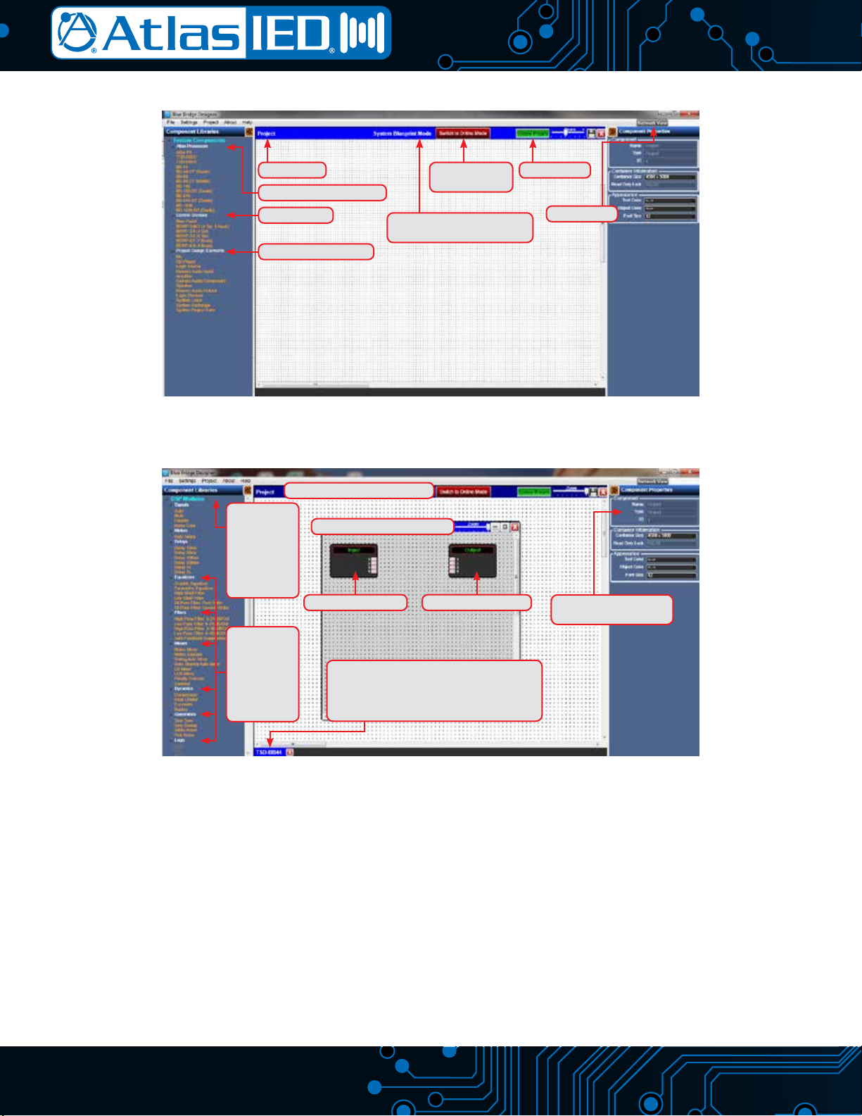
The following is a Quick Start Guide to be used with the Atlas Sound BlueBridge processors. These models are part of the BlueBridge family of
processors that are based on an open architecture platform that utilizes a drag and drop method for system designs. The intent for this Quick Start
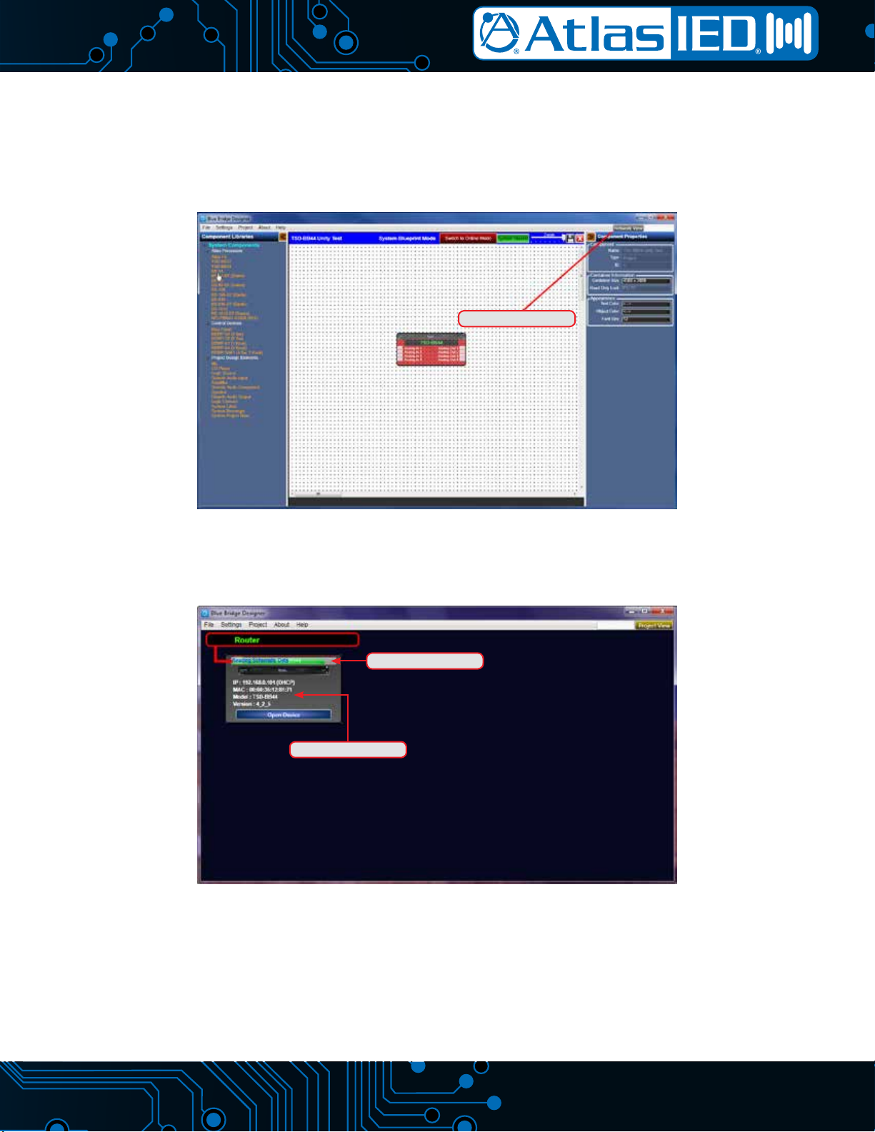
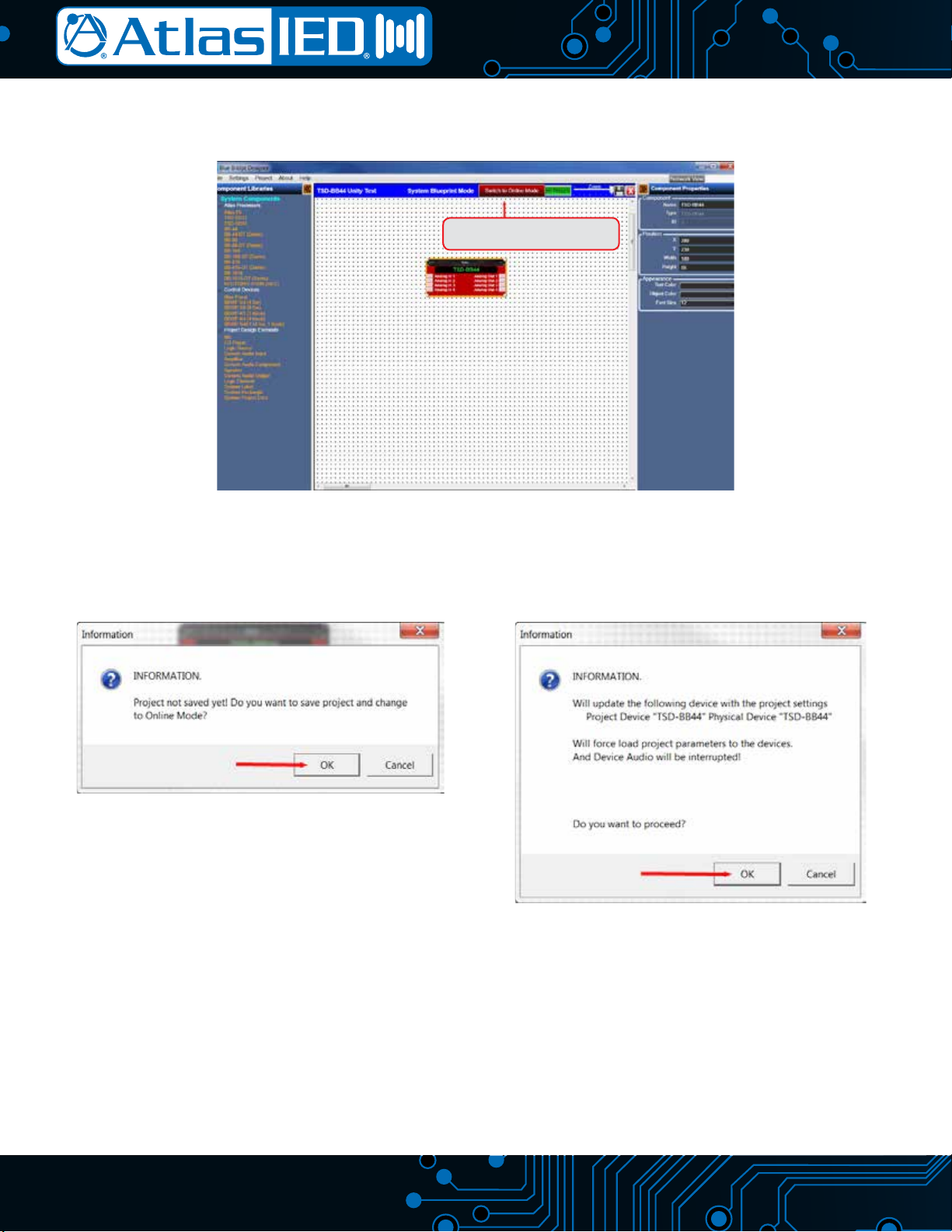
Guide is to give an overview on how to connect a BlueBridge device to a computer and access a DSP Hardware Block with the ability to pass audio
through the Atlas processor. When comparing BlueBridge to other DSP software, you will see that it is user friendly. However, these are technical
products and may take additional training to understand fully. After finishing this introduction guide, visit www.AtlasSound.com and review our
BlueBridge “How To” library of support materials.
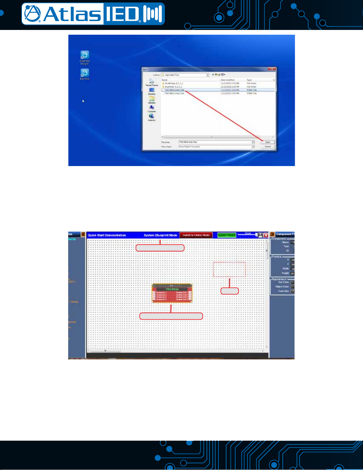
This guide focuses on the TSD-BB44 model as the example, although the same process of connectivity and design applies to all BlueBridge models.
The TSD-BB44 is configured with 4 (Inputs) x 4 (Outputs). All BlueBridge models share the same software and can be used within the same system
design.
Things To Know Before Starting
• BlueBridge models BB88, BB816, BB168, and BB1616 contain the following in each box, Atlas Sound BlueBridge processor, power cord, USB
thumb drive, Quick Start Guide. Each TSD-BB22/44 box contains: TSD-BB22 or TSD-BB44, power supply, USB thumb drive, (2) mounting
brackets, Velcro strip, and (2) cable management retainer clips.
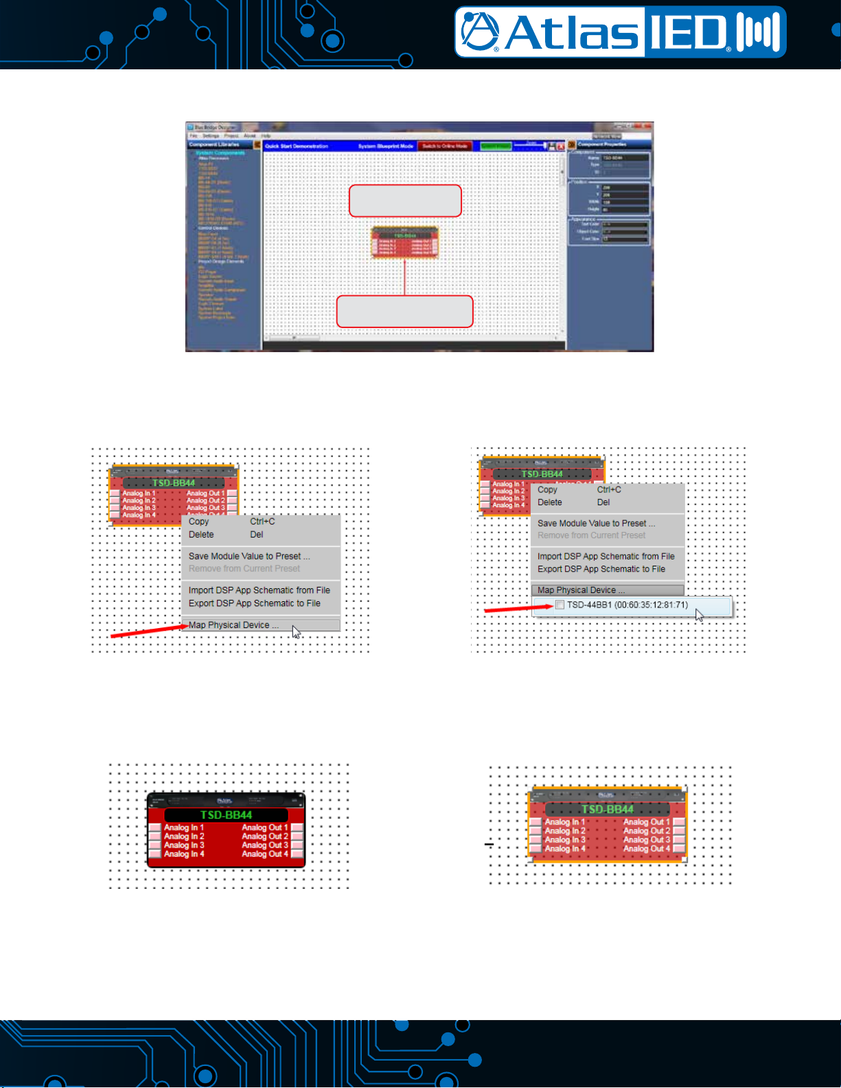
• The TSD BlueBridge models are factory preset to allow audio to pass in a unity gain configuration from Input 1 to Output 1, Input 2 to Output 2,
etc. This will be useful for system set-up or troubleshooting if needed.
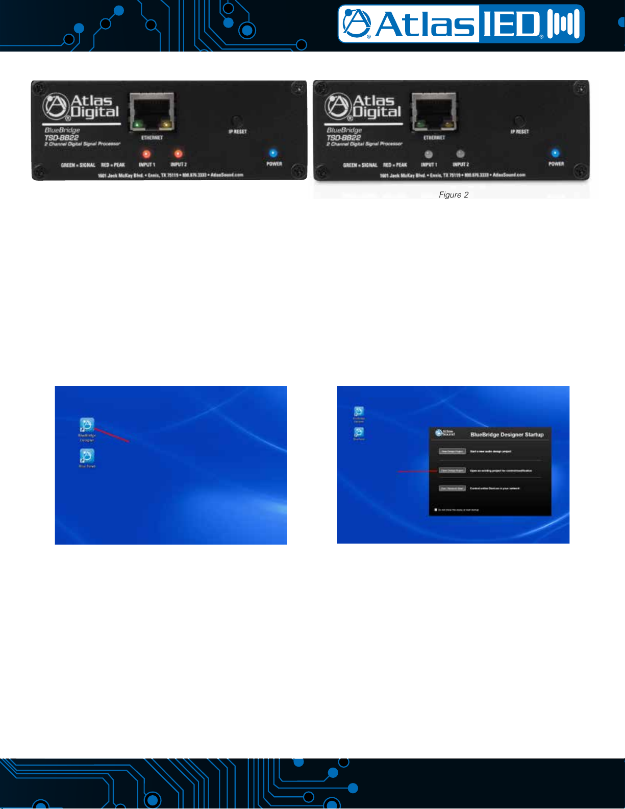
• The included USB thumb drive contains the BlueBridge software which is required to connect to the TSD/BlueBridge device. BlueBridge is
continually improving and adding features, ALWAYS check the Atlas Sound web page for the latest software and firmware updates prior to starting
a new design. If an update is needed, follow the Reference Guide for BlueBridge Firm Upgrade. This guide is also on the USB drive provided.
• BlueBridge software and firmware versions are forward/backward compatible for basic operation. However, when importing an older system
design file onto a new device, Atlas Sound recommends using the latest software and firmware versions to ensure the system design is fully
operational and bug free.
• Once the BlueBridge device is connected and communicating with the computer, review the BlueBridge reference guide section titled “How To”
in order to familiarize yourself with the unit’s functionality. The BlueBridge platform is very powerful and includes a variety of features or shortcuts
that are explained in short specific segments.
• These models can be mounted in several ways to meet design requirements. Atlas Sound suggests reviewing the “TSD Installation/Mounting
Reference Guide.”
• The following are required to work with a BlueBridge device: (1) PC with a processor 1GHz or higher, (2) Windows®8, 7, Vista, or XP, (3) 500MB
of free space, (4) 1GB graphics card, (5) 512MB of RAM, (6) Ethernet Interface.
BlueBridge Family
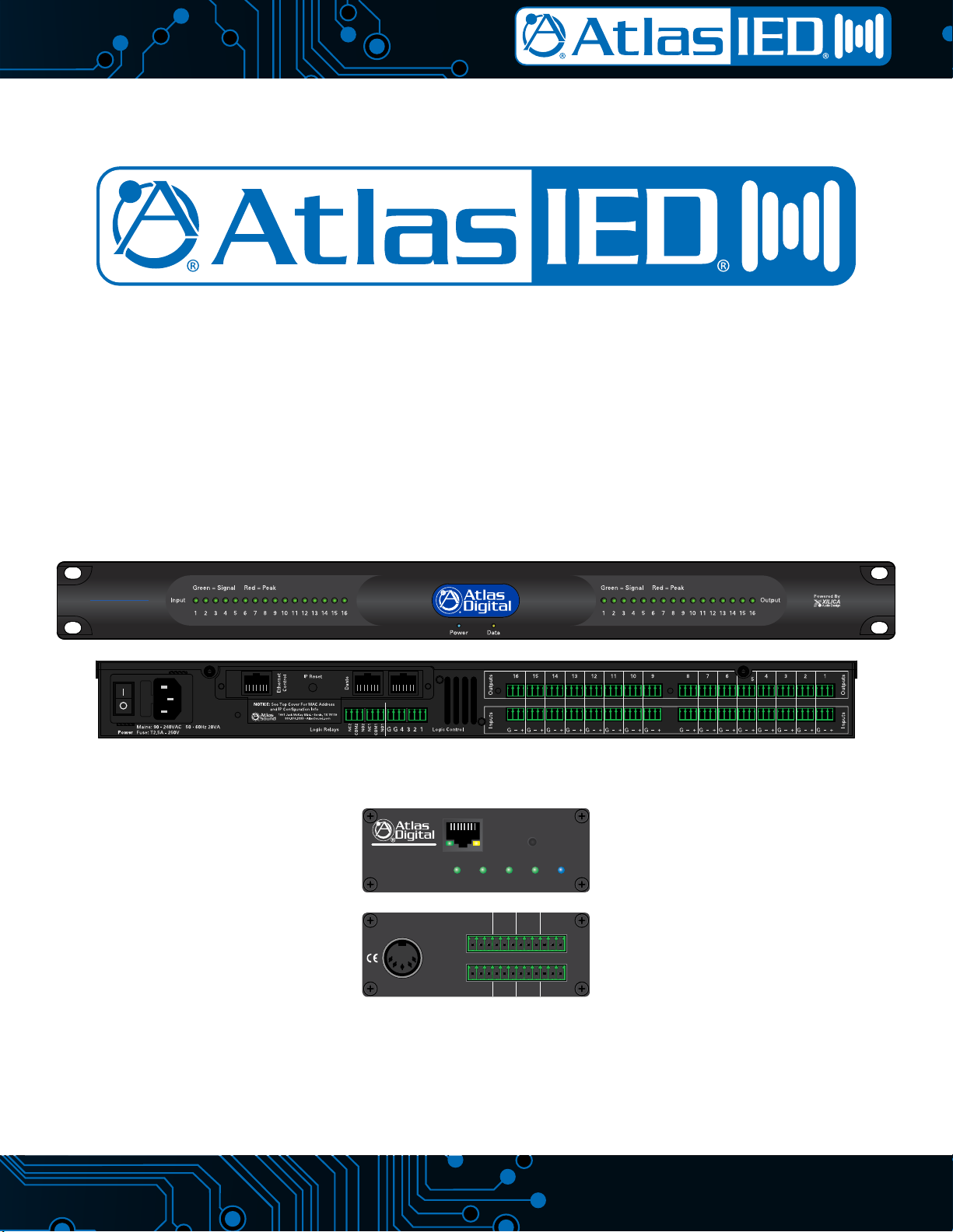
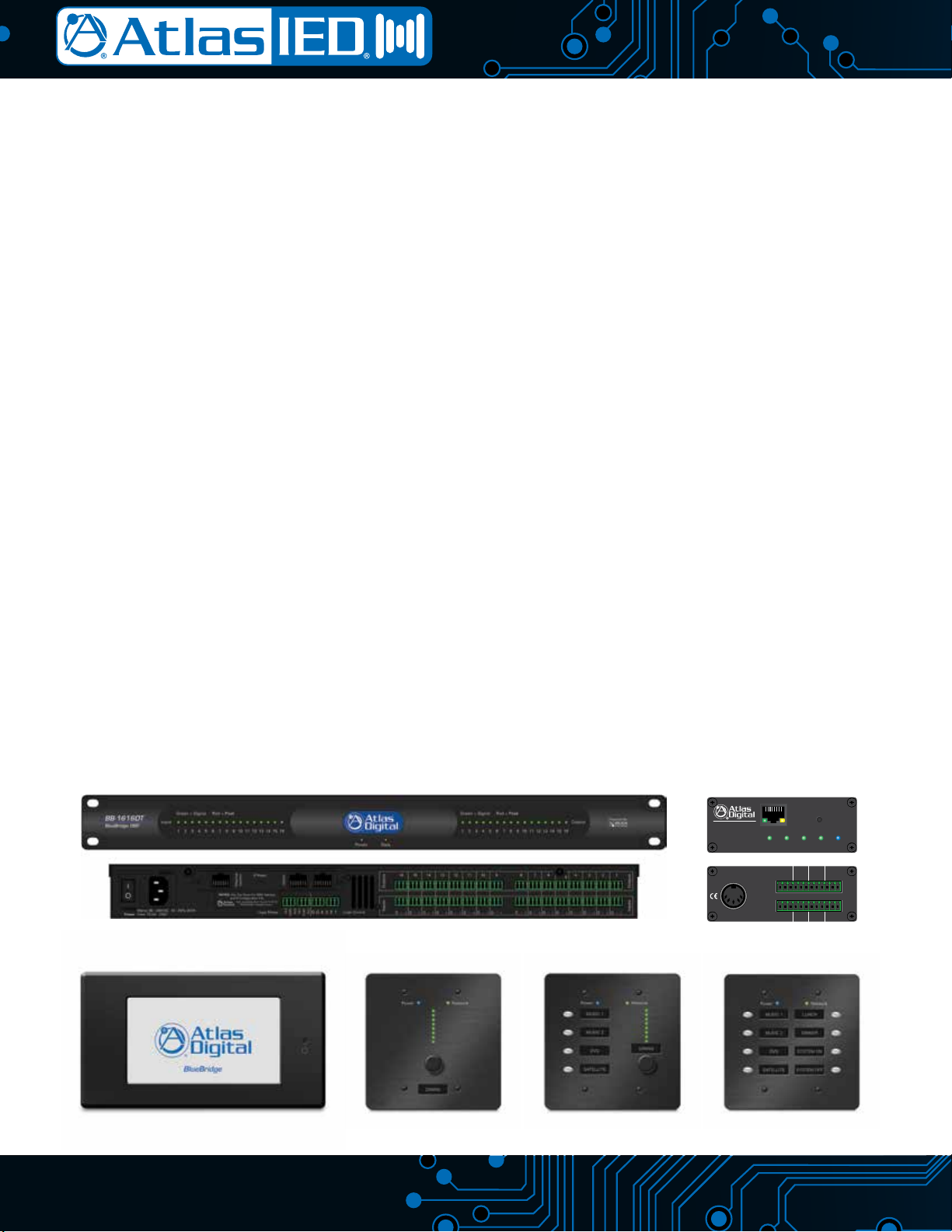
The BlueBridge DSP family consists of many components including an 8x8, 8x16, 16x8, and 16x16 unit as well as the TSD-BB22 and TSD-BB44
modules. The 1 RU models have incorporated logic ports and relay contacts. Most of those models are also offered in a DT, Dante version. There are
several other supporting accessory items available including wall controllers and touch screens.
BBWP-TOUCH7B BBWP-K1 BBWP-S4K1 BBWP-S8
1601 Jack McKay Blvd. • Ennis, TX 75119 • 800.876.3333 • AtlasSound.com
POWERINPUT 1 INPUT 2 INPUT 3 INPUT 4
IP RESET
ETHERNET
GREEN = SIGNAL RED = PEAK
G – +
INPUT 2
G – +
INPUT 1
G – +
OUTPUT 2
G – +
OUTPUT 1
INPUT 4
G – +
INPUT 3
G – +
OUTPUT 4
G – +
OUTPUT 3
G – +
5V/12V/-12V
20W TOTAL
EXTERNAL DC
POWER SUPPLY
BlueBridge
TSD-BB44
4 Channel Digital Signal Processor
ATLAS DIGITAL BLUEBRIDGE IP CONFIGURATION
MAC ADDRESS
SERIAL NUMBER
SCAN FOR TROUBLESHOOTING
TSD-BB44BB-1616DT
AtlasSound.com
3/16
BlueBridge Glossary ofTerms
BlueBridge Designer - The Software program used to create a Design Template to load into an Atlas BlueBridge DSP device.
Blue Panel - A Software program used to identify DSP hardware devices on a network and navigate custom control pages created for the devices
using the BlueBridge dsigner software.
Atlas Processor (Hardware Block) - The actual DSP hardware device to be dragged onto the System Blueprint page to base the system
design around.
System Blueprint Mode - BlueBridge Designer mode used to create a diagram of the overall audio design of a project.
Online Mode - The state when the design file is loaded into the designated hardware and ready for use. At this point the unit is “Live” and all
changes can be heard in real time.
Component Libraries - This navigation pane within BlueBridge Designer has 2 modes. In the Project Design mode it will show the available System
Components that can be used for the project. Once a DSP module has been placed in the design and opened, the Component Libraries
change to show the available DSP Modules that can be placed within the DSP Device.
Component Properties - This navigation pane within BlueBridge Designer allows the user to make changes to all of the elements in the design.
These elements can include Component Name, Position, Appearance, Number of Inputs/Outputs etc. This pane will also track the Component
Resource Usage of the DSP Device.
Design Template - A pre-configured design that can be used as template to create a new custom design. These files can save the designer a lot of
time. Go to www.AtlasSound.com in the BlueBridge section to see additional designs if they are not listed in the software. Note: Design
Templates are not to be confused with the term APPs that are used in other DSPs. An APP is a fixed designed that cannot be reconfigured.
Network View - This Button displays the “Network View” page showing all of the DSP hardware and control devices that have been found on the
Network. Note: This button is only available in Project View.
Project View - This Button displays the “Project View” page showing the current project design layout. Note: This button is only available in
Network View.
DSP Module (Processing Block) - The Icon for the DSP processing module that is used/placed inside the Atlas DSP Device (Hardware) Block.
There are many DSP modules to select from such as Meters, Delays , EQs, Filters, and Mixers to name a few.
Control Page - A window or several windows with control elements, ie: faders, buttons, meters, etc. used to create a custom user interface
experience.
Control Device - Hardware devices or Blue Panel software used to control system settings configured with control pages with the BlueBridge
Designer software.
Device Resource - Indicates the amount of DSP resources used for the selected DSP hardware or individual processing blocks. This can be found in
the Component Properties navigation pane. This can be viewed while Online or Offline for Hardware resources, and Offline for the processing
blocks. There is a resource button on the top of the window of an open hardware block when in Online Mode.
System Presets - Preset values for routings, volumes, EQ etc can be created and stored in the system design for recall when needed i.e. Scenes.
Dante - Digital Audio Transport System designed by Audinate to transport uncompressed full bandwidth audio over standard gigabit network hardware.
Digital Trim - Fine adjustment of input signal Post (after) the Analog Input stage.
Analog Trim - Fine Adjustment of the analog Mic/Line preamplifier Pre (before) the A/D converter.
Auto-Wire - The method used to wire Hardware and Processing Blocks without having to navigate a “point to point” wiring system. Wires can be
adjusted and labeled if desired after blocks are connected.
Cable Label - A way of identifying wiring for an audio system design. Can be done in the Component Properties when selecting a wire that has been
brought into a design.
Refer to Figure A and Figure B on the following Page for glossary term/feature location identification tags.
TELEPHONE: (800) 876-3333
FAX (800) 765-3435
4/16
BlueBridge Designer Software Glossary Term/Feature Location Identication Tags
Figure A shows the BlueBridge Designer main starting page. This is called System Blueprint Mode.
Figure B shows the BlueBridge Designer Software with the TSD-BB44 DSP processor block opened.
Figure B
In System Bluprint Design Mode
Atlas TSD-BB44 DSP Processor
Hardware Input Block Hardware Output Block Component Properties
(User Defined and Named)
DSP Modules
(Drag a Module
Into the DSP
Hardware
to Custom
Configure
DSP Module
Types:
Meters
Delay
Equalizers
Mixers etc.
Indicated the Open Atlas Processor In the
Functional System Design (There Can Be More
Than One Atlas Processor In a System Design,
But Only One Design File Per Processor.
Figure A
Project View System Preset
Network View
Online Mode
(AKA Live Mode)
System Blueprint Mode
(AKA Functional Wiring Diagram)
Control Devices
Project Design Elements
Atlas Processors (Hardware)
AtlasSound.com
5/16
Turning The Unit On
After connecting the power supply, the front panel input LEDs will illuminate red for approximately 60 - 120 seconds as shown in Figure 1. The interior
relays will audibly click and then the input LEDs will turn Off. The power and ethernet LEDs will remain illuminated as shown in Figure 2.
The TSD-BB22 and TSD-BB44 are factory pre-loaded with a file that connects Input 1 to Output 1, Input 2 to Output 2, etc. When using balanced input
signals, follow the wiring information on the rear panel and for unbalanced input wiring combine the (G) and (-) pins.
Loading the BlueBridge Software and Test Files
• The included USB drive contains both the BlueBridge Designer and BluePanel software packages.
• Insert the USB drive into an available USB port on your computer. Access the thumb drive through Windows®explorer and find the folders for
Designer and BluePanel. Install both of these software applications onto your computer. Note: Always check www.AtlasSound.com for the latest
release before installing.
Figure 3
Launch the BlueBridge Designer Application.
Figure 4
Select the “Open Design Project” Button and a Dialog
Box Will Open to Choose a Design File
Figure 2Figure 1
TELEPHONE: (800) 876-3333
FAX (800) 765-3435
6/16
Choose the Unity Test file for the unit being installed and select “Open” as shown in Figure 5. This design file will provide basic information for loading
a design file onto the device.
The Unity Test file will open in the BlueBridge Designer application as illustrated in Figure 6.
• An Atlas DSP Block representing the device will appear shaded on a grid background as shown in Figure 6.
• The next step will be to map the design file to the hardware found on the Network View.
Figure 5
Open Unity Design Test File for Model Being Installed
Figure 6
BlueBridge Designer Application Running Unity Test Design File in System Blueprint Mode
TSD-BB44 DSP Processor Block
System Bluprint Mode
Grid
AtlasSound.com
7/16
Connecting The Device to the Network
• Connect a Windows®computer to the network (wired or wireless).
• Connect the device to the network using a standard Cat5e ethernet cable.
• Ensure that DHCP is enabled in your computer’s network settings.
• Access the BlueBridge Designer software and choose “Network View” to locate the hardware connected to the network.
After clicking “Network View”, a page will open that shows all BlueBridge hardware units that are connected to the network as shown in Figure 7.
• In the Network View, the device can be identified by IP address, MAC address, model #, or Firmware Version as shown in Figure 8.
• The window will show the status bar and then the device will appear and indicate the upload progress as shown in Figure 8. Note: It is possible
for it to take few minutes to detect the device. If it does not detect the device, reset (cycle) the power to the device by unplugging the power
cable and waiting 30 seconds before plugging it back in. The upload progress is only shown when the device is initially plugged into A/C power.
Figure 7
Click on Network View
Figure 8
Status Bar
Unit Identification
TELEPHONE: (800) 876-3333
FAX (800) 765-3435
8/16
• Note: If you have used this software with any Atlas BlueBridge hardware devices that were previously connected, you may still see them appear
in the Network view as shown in Figure 9. These can be identified by the model number. The RED dot in the upper left corner of the device
window indicates the device is no longer detected.
• You can remove the unused hardware device by right clicking on the device you want to remove and select ”Remove Device From Console” as
shown in Figure 9.
• Once the Atlas BlueBridge hardware device is detected on the network and the status indicator is Green, return to the Project View so the device
can be “Mapped” to the design file as shown in Figure 10.
Figure 10
Project View
Unit is Detected
Figure 9
Not Detected
Detected & Connected
AtlasSound.com
9/16
• Click on the “Project View” button as shown in Figure 10. This will take you back to the Blue Print Mode window view. The detected unit will now
appear in the main window as shown in Figure 11.
• Right Click the TSD Hardware to “Map Physical Device” and follow the steps shown in Figures 12 and 13 below.
• Once the unit is “Mapped” the DSP Hardware block for the unit will no longer be shaded as shown in Figure 14.
Figure 12
Go to the drop down menu and select "Map Physical Device"
Figure 13
Click the box of the device that will be linked to this design file.
Note: There may be more than one unit listed, use the MAC
address for identification.
Figure 14
Unit is Mapped
Figure 15
Unit is NOT Mapped
Figure 11
Right Click On Hardware
Device To Map the Device
Unmapped DSP Unit
Will Appear
TELEPHONE: (800) 876-3333
FAX (800) 765-3435
10/16
Conguring the Unit Online
Note: When in Online Mode, the BlueBridge Hardware Device and the Design File are communicating and all adjustments are live and in real time.
• Click the button ”Switch to Online Mode” to go from System Blueprint Mode (Functional Wiring Diagram) to Online (Live) mode, in the menu bar
as shown in Figure 16.
• The software will generate new information windows. Click the OK button to proceed as shown in Figures 17 & 18.
Figure 17
Figure 18
Figure 16
Click To Switch From System
Blueprint Mode To Online Mode