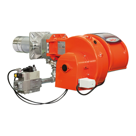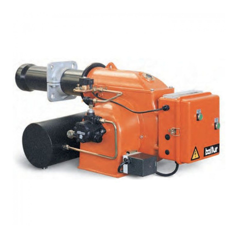
Operation and Maintenance Manual - GB
GB
www.atmos.cz GB-3
CONTENTS
1. General information 4
Introduction 4
Application 4
Technical specifications 4
2. Design 5
Description 5
3. Burner accessories 9
4. Safety, burner installation and commissioning 10
Safety and connection of the burner to the boiler 10
Basic dimensions of the opening for installation of the burner in a boiler 11
5. Type of environment and location of the boiler with the burner in the boiler room 13
6. Chimneyn 13
7. Flue gas duct of the boiler 14
8.
Fire protection within the installation and use of heat appliances
14
9. Basic connection diagram of a D30P, D31P, P31 a D45P boiler with an accumulation tank for burner
control on the basis of TS and TV sensors 16
10.
Connection of boilers
D30P, D31P, P31 a D45P
with an accumulation tank for burner control on the basis
of TS and TV sensors and control of the boiler pump on the basis of the TK sensor 17
11. Connection of boilers
D30P, D31P, P31 a D45P
with an accumulation tank with solar heating for burner
control on the basis of TS, TK and TV sensors (automatic sensor switching function), function of controlling
the solar pump based on TSV and TS tempera 18
12. Connection of boilers D30P, D31P, P31 a D45P with electronic regulation ACD01 and accumulation tank
with solar heating 19
13. Connection of boilers DCxxS, CxxS, ACxxS, KCxxS, DCxxRS with built-in burner in upper doors with
accumulation tank for regulation of the burner based on sensors TS and TV and control of boiler pump
based on TK sensor 20
14. Connection of boilers DCxxS, CxxS, ACxxS, KCxxS, DCxxRS with built-in burner in upper doors and
with ACD01 electronic regulation 21
15. Connection of the boiler and burner to the electric mains 22
16. Connection diagram of the electronic unit AC07X 23
17. Electric diagram of the burner ATMOS A45 - 6-pin connector - model 2012 AC07X - (R, R2, sensors TV,
TS, TK, TSV) 24
18. Electric wiring diagram connection of the boilers D30P, D31P, P31 a D45P with extraction fan, model
2012 with 6-pin connector and module AD02 - to control extraction fan of the boiler from burner control
unit AC07X (R) 25
19.
Electric wiring diagram connection of the boilers D30P, D31P, P31 a D45P with extraction fan, model
2012 with 6-pin connector and module AD03 - to control extraction fan of the boiler and pump in the
boiler circuit from burner control unit AC07X (R and 26
20. Electric wiring diagram connection of the boilers DCxxS(X), DCxxS, ACxxS, DCxxRS with extraction
fan, model 2012 with 6-pin connector and module AD03 - to control extraction fan of the boiler and pump
in the boiler circuit from burner control unit AC07 27
21. Commissioning 28
22. Control and setting of the burner 30
Display and control panel 30
Passwords and their functions 32
PARAMETERS menu 32
Setting the required power and combustion quality: 33
INFORMATION menu 49
TESTING menu 50
23. Information - error messages - troubleshooting 51
General troubleshooting 51
Table of error messages on the display - alarms 51
If no problem has been found, reset the regulation AC07X by the RESTART command. 56
If the system is working, but you are not satisfied with its function, proceed as follows: 56
24. Maintenance and cleaning of the burner 57
25. List of spare parts 59
26. Expanded view of the burner 60
GUARANTEE TERMS 61
RECORD OF INSTALLATION OF THE BOILER AND BURNER
62
ANNUAL INSPECTIONS RECORDS 63
RECORDS OF GUARANTEE PERIOD AND POST-GUARANTEE PERIOD REPAIRS 64


