Atmos i View PRO Series User manual

ATMOS i View PRO
GA1GB.120102.0
2022-04 Index: 19
Operating Instructions
English

2
Table of contents
4.4 Adjusting the interocular distance.......................16
4.5 Adjusting the eyepieces......................................16
4.6 Exchanging the lenses........................................17
4.7 Exchanging the lenses with manual ne
focusing...............................................................17
4.8 Exchanging the VarioFocus lens.........................17
4.9 Adjusting the 5-fold magnication changer.........17
4.10 Focusing .............................................................18
4.10.1 Fine focusing.......................................................18
4.11 Exchanging the binocular tube............................18
4.12 Binocular rotary disk with detent.........................18
4.13 Pivoting H.A.S.I. lter..........................................18
4.14 Shadowless illumination......................................19
4.15 Microscope zoom and object eld size ...............19
4.16 Measuring scale..................................................19
4.17 Image and video recording .................................20
4.17.1 Adjusting the light mode of the integrated
HD camera..........................................................20
4.18 Endoscope adapter.............................................21
4.19 HD adapter..........................................................21
5.0 Cleaning and care.............................................22
5.1 General information on cleaning
and disinfection...................................................22
5.2 Cleaning the mechanical microscope surface ....22
5.3 Cleaning the lenses/eyepieces ...........................22
5.3.1 Cleaning optical surfaces....................................22
5.3.2 Optical surface of the endoscope connection.....22
5.3.3 Fogging of optical surfaces.................................23
5.4 Recommended surface disinfectants..................23
5.5 Hygiene plan.......................................................23
6.0 Maintenance and service .................................24
6.1 General advice....................................................24
6.2 Sending in the device..........................................24
6.3 Exchange of spare parts.....................................24
7.0 Troubleshooting................................................25
8.0 Accessories and options .................................26
9.0 Technical Data...................................................27
10.0 Disposal.............................................................28
11.0 Notes on EMC....................................................29
12.0 Notes..................................................................30
1.0 Introduction.........................................................3
1.1 Notes on operating instructions ............................3
1.2 Intended purpose..................................................4
1.3 Function ................................................................5
1.4 Explanation of pictures and symbols ....................6
1.5 Scope of supply ................................................... 7
1.6 Transport and storage...........................................7
2.0 For your safety....................................................8
3.0 Setting up and starting up .................................9
3.1 Overview.............................................................. 9
3.2 Setting up............................................................10
3.2.1 Connection to the power supply..........................10
3.2.2 Microscope overview ..........................................10
3.2.3 Operating elements on the microscope ..............11
3.2.4 Rear view of the control device of the
ATMOS i View 21 PRO ...................................... 11
3.2.5 Rear view of the control device of the
ATMOS i View 31 PRO (not with an integrated HD
camera)...............................................................11
3.2.6 Rear view of the control device of the
ATMOS i View 31 PRO with an integrated
HD camera..........................................................12
3.3 Integration options ..............................................12
3.4 Starting up...........................................................13
3.5 Operating requirements ......................................13
3.6 Starting up at a glance........................................14
4.0 Operation...........................................................15
4.1 Microscope suspension ......................................15
4.2 Mechanical arm...................................................15
4.3 Hand grips...........................................................15
4.3.1 T-hand grip..........................................................15
4.3.2 Lateral double hand grip .....................................15

3
1.0 Introduction
1.1 Notes on operating instructions
These operating instructions contain important notes on how to operate the ATMOS i View PRO safely,
correctly, and e ectively. Their reading helps to avoid risks and also to reduce repair costs and down-
times. This increases, among other things, the reliability and service-life of the microscope.
These operating instructions serve not only for new operating personnel to be instructed in its use, but
also for use as a reference manual. Reprints (also in extracts) only with permission in written form by
ATMOS.
These operating instructions must always be kept available near the microscope.
Care and safety inspections in conjunction with professional execution provide for operational safety and
readiness for use of your ATMOS i View PRO and are therefore a must besides regular cleaning.
Repair work and safety inspections may be carried out only by expert personnel authorized by ATMOS.
By applying only original spare parts, you will have the guarantee that operational safety, readiness for
work, and the value of your ATMOS i View PRO will be preserved.
• This device bears the CE marking CE in accordance with the European Medical Device Regulation
(MDR) 2017/745.
• The product ATMOS i View PRO complies with all applicable requirements of Directive 2011/65/EU
restricting the use of certain hazardous substances in electrical and electronic equipment (“RoHS”).
• The Declarations of Conformity and our General Terms and Conditions can be viewed on our website
at www.atmosmed.com.
• The quality management system applied at ATMOS has been certi ed according to international
standard EN ISO 13485.
• Prior to start-up, please peruse chapter 2.0 “For your safety” in order to be prepared for any possible
dangerous situations.
Please keep this document for future consultation!
These operating instructions are valid for the following devices:
ATMOS i View 21 PRO REF 538.9000.0
Examination microscope with an integrated, fanless, high-transmission, high-performance LED light source in the microscope
head, 30° coupling included
ATMOS i View 31 PRO REF 539.9000.0
Examination microscope with an integrated, fanless, high-transmission, high-performance LED light source in the microscope
head, 30° coupling included

4
1.2 Intended purpose
Product name: ATMOS i View 21 PRO
ATMOS i View 31 PRO
Main functions: The device is a microscope intended to give a magnied illuminated spacial
view on human tissue for diagnostic and treatment purposes.
Intended purpose: Standard ENT examination and treatment of ear, nose and throat and surgi-
cal interventions
Intended Users / User prole: Doctors and medical specialists
Intended Patient population: All patients without any restrictions
Medical conditions to be diagnosed, treated
or monitored:
Diagnostic examination of anatomy of all kinds
Application organ: Ear, Nose, Throat
Application time: 60 min – 30 days
Application site: Outpatient medical facilities, e.g. ENT practices, hospital outpatient depart-
ments, medical care centers
Patient selection criteria: None
Indications: Standard ENT examination and / or therapy
Medical contra-indications: None
Other contra-indications: None
Warnings: None
The product is: Active
Sterility/specic microbial status: Not steril
Single use product / reprocessing: Not a single use product. Reprocessing according to instructions for use.
1.0 Introduction

5
1.0 Introduction
1.3 Function
The ATMOS i View PRO is a complete microscope system consisting of optics and lighting. It produces outstanding pictures for
examination purposes with the use of latest LED technology and patent registered optics. The interaction between the integrated
fanless, high-transmission, high-performance LED, the apochromatic optics and the precisely adapted options oer best working
quality.
The ergonomically arranged buttons, two selectable hand grip variants, and the integrated control panel provide the user with the
highest level of ergonomic comfort and suitability for daily use as well as outstanding and intuitive handling. Via the control panel,
the individual options of the ATMOS i View PRO can be activated. Besides triggering the camera (freeze frame) and starting/stop-
ping possible video sequences, the operator is capable of manually switching the LED light source on and o despite the activated
automatic light control. Due to the variety of options the ATMOS i View PRO has to oer, the user is in a position to congure a
microscope to suit his requirements. The following functions can be chosen optionally:
• 4 lenses with dierent focal distances (200, 250, 300, and 400 mm) with or without ne focusing or a VarioFocus 200–500 mm
(easy exchange of lenses due to the respective thread on the microscope head)
• Binocular straight lens tube, binocular angled lens tube and binocular swivel tube, simple adaption due to the dovetail xation (0°
or 45° angle)
• Pivoting color lter
• Measuring scale
• Shadowless illumination
Due to the LED light source and the integrable camera solution (HD integrated respectively as HD or endoscope adapter for the
connection of an external camera), the ATMOS i View PRO is a guarantor for best image quality.
In combination with the mechanical carrier arm and the numerous connection possibilities to units and stands, the ATMOS i View
PRO oers countless system possibilities that can be individually adapted to suit the user’s environment.
)These operating instructions describe all functions with a maximum conguration of the ATMOS i View 31 PRO.

6
1.4 Explanation of pictures and symbols
1.0 Introduction
Short cuts / symbols contained in these operating instructions
Follow the arrows, sequence Check
Please press where dot indicates Move, plug ... in this direction
Please read, important information Turn, shift ... in this direction
■General information Replace
●Numeration click Engage, check correct t
Warning, pay special attention Important information
Symbols ATMOS i View PRO
SN Serial number REF Reference number
Date of manufacture Manufacturer
Consult operating instructions Follow operating instructions (blue)
Weight adjustment for the carrier arm Professional disposal
Alternating current Fuse
2Do not reuse
Exchange after use
This device complies with the relevant require-
ments of EU regulations.
Do not look directly into the light source of the
ATMOS i View UL Listing Mark
This device complies with the relevant require-
ments of the Eurasian Economic Union.
MD Medical device
UDI Unique Device Identi er of a medical device Humidity limitation
700
1060
Atmospheric pressure limitation Temperature limit
This side up Fragile, handle with care
Keep dry Country of manufacture
060.0604.0
Schild Transportst. Mikolp
Label transport position Mikolp
1:1
01
9463/13
15.07.13
OEI
24.07.13 O.Eirich
Blatt
(sheet) 1
Bl.1/1
(index)
Zust. (revision)
Änderung Datum
(date) Name
(name)
Maßstab (scale) Konstr. Nr.
Gepr.
Bearb.
Name
Erstellt
Datum
Ers.f. : Ers.d. :
Benennung (description)
Zeichnungs /
Artikel-Nr.
(part no.)
Alle Maße in mm/
all dimensions in mm
Allgemeintoleranzen /
General tolerances
DIN ISO 2768 - mK
79853 Lenzkirch / Germany
MedizinTechnik
ATMOS Medizin T echnik GmbH & Co. KG
Ludwig - Kegel - Str. 16
Tel: +49 7653 689 -0
Fax: +49 7653 689 -190
www.atmosmed.de
Schutzvermerk (Copyright notice) DIN ISO16016
A4
3M Folie7876EC+Laminat 7730FL
nicht bemaßte Radien R5
weiß
transparent
RAL 5005 Signalblau
RAL 3001 Signalrot
schwarz
02
9576/13
22.11.13
OEI
C.Reinhardt
09.01.14
09.01.14 C.Reinhardt
Mobile stand transport position
Do not lean against the device

7
1.0 Introduction
1.5 Scope of supply
Prior to dispatch, the ATMOS i View PRO was subjected to an extensive functional test and was carefully packed. Nevertheless,
please compare the contents of the shipment on completeness immediately upon receipt (see delivery note).
1.6 Transport and storage
• After the transport of the ATMOS i View PRO at temper-
atures below 0 °C, it should be kept at room temper-
ature for at least six hours prior to rst start-up. If the
ATMOS i View PRO is not acclimatized, it may not be
used as damages to the electronic components could
occur.
Only transport the device in a shipping carton that is pad-
ded and oers sucient protection.
If damage occurs during transport:
• Document and report the transport damage.
• Send the device to ATMOS (see chapter “6.2 Sending
in the device” on page 24).
Ambient conditions:
• Transport/storage:
- −10...+50 °C;
- 30...95 % air humidity without condensation
- air pressure 500...1060 hPa
• Operation:
- +10...+35 °C;
- 30...95 % air humidity without condensation
- air pressure 700...1060 hPa
UDI application identier
ATMOS i View 21 PRO ATMOS i View 31 PRO
(1) 04250365177251 (1) 04250365177268
(11) 210420 (11) 210420
(21) 1122334 (21) 1122334
Control panel buttons ATMOS i View 31 PRO
Light on/o (independent of automatic light
control)
Switch stroboscope – permanent light
With integrated HD camera: Adjustment of the
camera’s light mode
Video recording (start/stop) Freeze frame
Control device ATMOS i View 21 PRO
Output of the power supply for the electron-
ics in the microscope Potential equalization acc. to IEC 60417-5021
Fuse
Control device ATMOS i View 31 PRO
Fuse Potential equalization acc. to IEC 60417-5021
Microscope Foot switch
Record function Freeze
Triggering signal from ATMOS Strobo 21
LED
HD camera: not in use
Output signals of the tilt sensor in the carrier arm
system
USB port
Sensor
Strobo
Extern 2
PC/USB
Video In
Record Freeze
Foot Switch
Out 1 Out 2 Out 3
Video Out
Microscope
Intern 1
Video In
2 x T 3,15A
100 - 240V~
Input video signal internal/external (only with an
integrated HD camera)
S-video output (not with an integrated HD
camera)
Sensor
Strobo
Extern 2
PC/USB
Video In
Record Freeze
Foot Switch
Out 1 Out 2 Out 3
Video Out
Microscope
Intern 1
Video In
2 x T 3,15A
100 - 240V~
Output video signal
(only with an integrated HD camera)

8
2.0 For your safety
!
For your safety
• Only proper and undamaged plugs and extension cables
may be used.
• To disconnect the ATMOS i View PRO from the power
supply, rst remove the plug from the wall outlet. Only then
can the connection cable from the ATMOS i View PRO be
disconnected. Never touch plug or cables with wet hands.
• Please observe the ambient conditions stated in the Tech-
nical Data (chapter 9.0).
• The ATMOS i View PRO complies with the electromag-
netic immunity requirements of standard IEC 60601-1-2
/ EN 60601-1-2 “Electromagnetic Compatibility – Medical
Electrical Devices.”
• ATMOS is not liable for personal injury and damage to
property if
- no original ATMOS parts are being used,
- the advice for use in these operating instructions is not
being observed,
- assembly, new settings, alterations, extensions, and
repairs have been carried out by personnel not author-
ized by ATMOS.
• Unplug the device immediately if you observe fumes,
sparks, or unusual noises.
• After lengthy use of the ATMOS i View PRO in connection
with an ear speculum, the patient may feel dizzy!
• With every light source, warming of tissue due to absorp-
tion may occur. Please make sure to reduce duration of
use to a minimum, to switch o the light source when not
in use, and to check heat development if necessary.
• Take into consideration when setting up the microscope
that the elastic force of the arm – without microscope head
– is exceedingly strong. Operate the brake of the height
adjustment carefully.
• Risk of injury! Take care not to roll the mobile stand over
your feet when moving it.
• Please note that only PCs and monitors with IEC 60601-1
/ EN 60601-1 / EN 60950-1 approval may be connected
to the video outlets of the ATMOS i View PRO supply
module!
• During operation, the user is obliged to regularly check the
microscope for proper function. In the unlikely event of fail-
ure, the user must take precautions to continue treatment
of the patient with suitable methods.
• Make sure that the device is positioned so that all the con-
trols and the on/o switch are always accessible.
• Report all serious incidents that have occurred in connec-
tion with this product to the manufacturer and your national
competent authority.
• To safely disconnect the unit from the power supply, the
power cable must be removed from the IEC connector of
the control device!
• The ATMOS i View PRO is a device designed in line with
IEC 60601-1 / EN 60601-1 and is a protection class I
device. In order to avoid the RISK of electrical shock, this
device may only be connected to a power supply with a
properly installed earth conductor.
• Power cables, accessories, and access cables need to be
checked for defects prior to starting up the ATMOS i View
PRO. Damaged cables must be replaced immediately.
• The ATMOS i View PRO may only be operated by qualied
personnel.
• The ATMOS i View PRO is not designed to be used in
explosion-hazardous environments. Explosion-hazardous
areas may be caused by the use of ammable anesthetics,
skin cleansing products, and skin disinfectants.
• The ATMOS i View PRO may be operated only in rooms
used for medical purposes, but not in areas subject to ex-
plosion hazards and in oxygen-rich environments.
• If uids have penetrated the ATMOS i View PRO, it must
be sent in and may only be used after being checked by a
person authorized by ATMOS.
• After transport of the ATMOS i View PRO at temperatures
below 0 °C or prior to rst start-up, it should be kept at room
temperature for at least six hours. If the ATMOS i View PRO
is not acclimatized, it may not be used.
• Do not plug in electric connections (plug, socket) under the
use of force. If this is not possible, check whether the plug
ts the socket. If you should ascertain a defect in the con-
nection, you should have it repaired by our service.
• Never look straight into the sun with the lens or eyepieces.
• Always make sure that you do not blind patients with the
light source! Watch out that patients do not look directly into
the light source!
Never look directly into the light source!
> Damage to the eyes due to the strong glare.
• Please pay attention to the periodic tests in chapter 6
“Maintenance and service” on page 24.
• Prior to every use, the microscope suspension (including all
joints) must be checked for safe connections.
• Take care that the patient does not touch the device or have
any contact with it.
• Please note that only the ATMOS Strobo 21 LED may be
connected to the strobe port of the ATMOS i View PRO
supply module!
• Please observe the EMC Directives. Failure to follow this
guideline can result in a hazard.
• Dispose of wrappings accordingly.
• Before connecting the ATMOS i View PRO, check whether
the line voltage and frequency specied on the
ATMOS i View PRO match the values of the power supply.

9
3.0 Setting up and starting up
3.1 Overview
ATMOS i View 21 PRO ATMOS i View 31 PRO
Description
Examination microscope with an integrated,
fanless, high-transmission, high-performance
LED light in the microscope head
Examination microscope with an integrated,
fanless, high-transmission, high-performance
LED light in the microscope head
Integrated high-per-
formance white light
LED
Automatic light
control
Optimized
stereo e ect
Measuring scale Optional Optional
Integrated control
panel Optional Optional
Color lter H.A.S.I. Optional Optional
Integrated camera - Optional HD camera
45° angled tube Optional Optional
Swivel tube 0-220° Optional Optional
Binocular rotary disk Optional Optional
HD adapter for an
external camera - Optional
Endoscope adapter - Optional
Mains voltage 100–240 V 100–240 V
Light output
min. 120 klx (200 mm)
min. 80 klx (250 mm)
min. 55 klx (300 mm)
min. 30 klx (400 mm)
min. 120 klx (200 mm)
min. 80 klx (250 mm)
min. 55 klx (300 mm)
min. 30 klx (400 mm)
Operating life of the
LED 50,000 hours 50,000 hours
Color temperature 5,500 K ± 10 % 5,500 K ± 10 %
Scope of delivery Dust cover,
operating instructions
Dust cover,
operating instructions

10
3.0 Setting up and starting up
5-fold magni cation changer
T-hand grip (optional)
Binocular tube with wide-
eld eyepiece lenses
Lens with ne focusing (optional)
Pivoting H.A.S.I. color lter (optional)
Brightness control
Lateral double hand
grip (optional)
Control panel (optional)
Endoscope adapter
(optional)
HD adapter for SONY
digital camera (optional)
Brakes of the coupling
Measuring scale
(optional)
3.2 Setting up
Please make sure that the static conditions stated by ATMOS MedizinTechnik are met (for details see the separately enclosed
document “Static requirements for installing the ATMOS i View”). The ful llment of these requirements must be con rmed by an
authorized expert.
Mains voltage and fuse: Mains voltage: 100–240 V, 50/60 Hz; Fuse: 2 x T 3.15 A
Please note that only PCs and monitors with IEC 60601-1 / EN 60601-1 approval may be connected to the video outlets of the
ATMOS i View PRO supply module!
Please note that only the ATMOS Strobo 21 LED may be connected to the strobe port of the ATMOS i View PRO supply module!
3.2.1 Connection to the power supply
Potential equalization:
The ATMOS i View’s supply module has a rear connection for potential equalization which can be connected to the potential equali-
zation rail in the room if need be. Hereby, user/patient safety can be increased especially in the case of a defective earth conductor.
For connecting the device’s potential equalization plug with the potential equalization rail of the room, use the potential equalization
cord with REF 530.0030.0.
3.2.2 Microscope overview
!

11
Ers.d. :
Zeichnungs /
Artikel-Nr.
(part no.)
Benennung (designation)
Werkstoff (material)
Konstr. - Nr:Mikolp-200-001.
Blatt
(sheet)
Zust.
(index)
Änderung
(revision)
Datum
(date)
Name
(name)
Gepr.
Bearb.
Name
Datum
Maßstab (scale)
1
Alle Maße in mm
all dimensions in mm
Allgemeintoleranzen /
General tolerances
DIN ISO 2768 - mK
über 30 mm ±0,3
Ers.f.:
Erstellt
79853 Lenzkirch / Germany
MedizinTechnik
ATMOS Medizin T echnik GmbH & Co. KG
Ludwig - Kegel - Str. 12, 14-16, 18
Tel: +49 7653 689 -0
Fax: +49 7653 689 -190
www.atmosmed.de
Schutzvermerk DIN ISO 16016
-
27.03.3013 C.Reinhardt
1:1 -
Tasterfolie
060.0621.0
M
M
O
O
D
D
E
E
LED AFD
STROBO
3.2.3 Operating elements on the microscope
Light on/o (independent of
automatic light control)
Video recording
(start/stop)
With integrated HD
camera: Adjust-
ment of the cam-
era’s light mode
Freeze
frame*
*When the button is pressed and held,
you can switch between freeze frame
and “Send trigger signal only” (for exter-
nal image recording).
3.0 Setting up and starting up
Output of the power supply for
the electronics in the micro-
scope
Connection for potential equaliza-
tion line acc. to IEC 60417-5021
IEC power plug with fuse
inlay for the connection to the
power supply
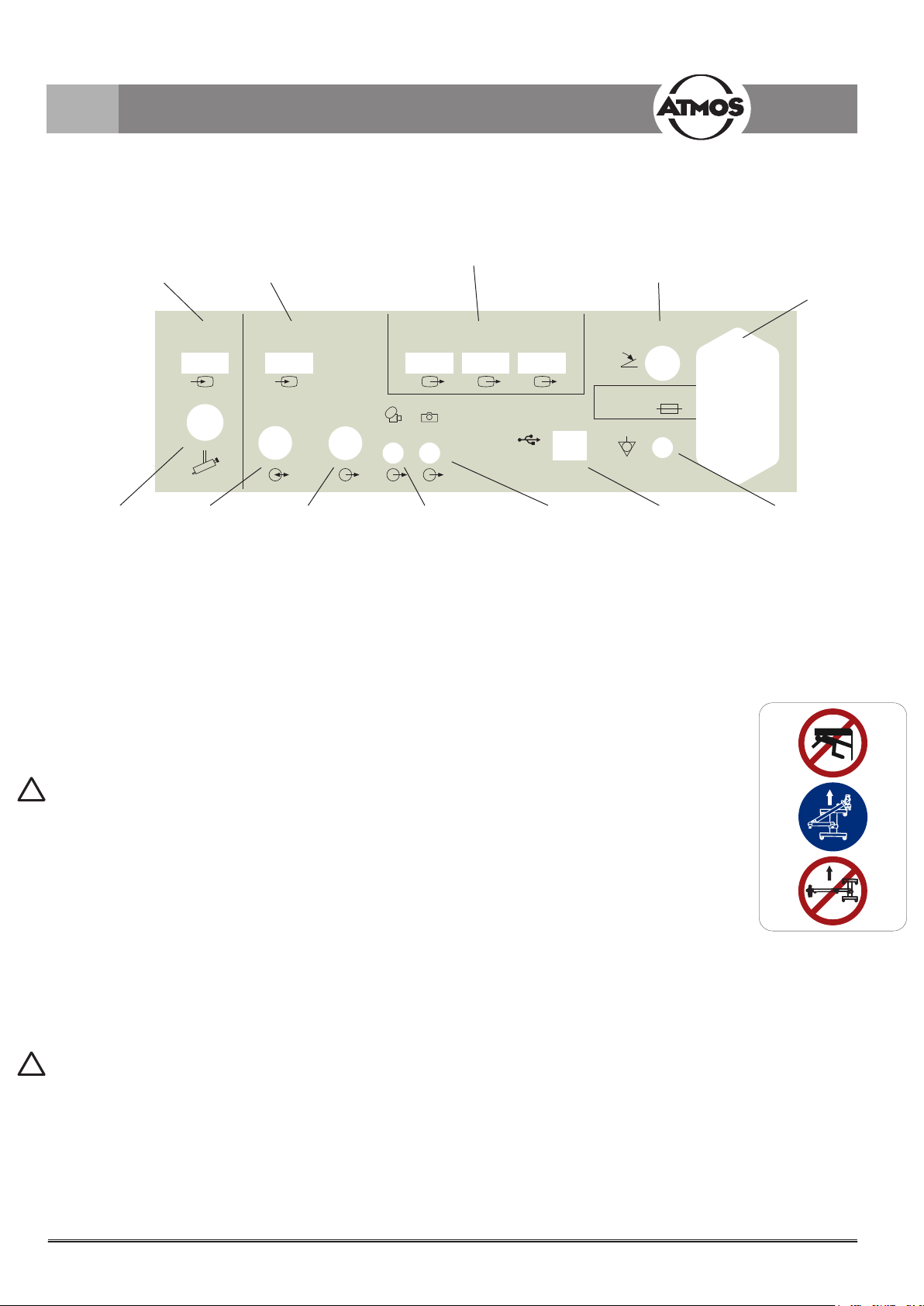
3.2.4 Rear view of the control device of the ATMOS i View 21 PRO
USB port for transferring
the key status of the
“Freeze frame” and “Vid-
eo recording” functions
Output signal of
the “Video record-
ing” function
Output signal of
the “Freeze frame”
function
Output signals of
the tilt sensor in the
carrier arm system
Output of the triggering
signal of the ATMOS
Strobo 21 LED
S-video outputs of
the integrated SD
camera
Connection for the
supply to the micro-
scope electronics and
control line
Connection to the foot switch
for switching between the light
channels
Connection for potential
equalization line acc. to
IEC 60417-5021
IEC power plug with fuse inlay
for the connection to the power
supply
3.2.5 Rear view of the control device of the ATMOS i View 31 PRO (not with an integrated HD camera)
12
060.0604.0
Schild Transportst. Mikolp
Label transport position Mikolp
1:1
01
9463/13
15.07.13
OEI
24.07.13 O.Eirich
Blatt
(sheet) 1
Bl.1/1
(index)
Zust. (revision)
Änderung Datum
(date) Name
(name)
Maßstab (scale) Konstr. Nr.
Gepr.
Bearb.
Name
Erstellt
Datum
Ers.f. : Ers.d. :
Benennung (description)
Zeichnungs /
Artikel-Nr.
(part no.)
Alle Maße in mm/
all dimensions in mm
Allgemeintoleranzen /
General tolerances
DIN ISO 2768 - mK
79853 Lenzkirch / Germany
MedizinTechnik
ATMOS Medizin T echnik GmbH & Co. KG
Ludwig - Kegel - Str. 16
Tel: +49 7653 689 -0
Fax: +49 7653 689 -190
www.atmosmed.de
Schutzvermerk (Copyright notice) DIN ISO16016
A4
3M Folie7876EC+Laminat 7730FL
nicht bemaßte Radien R5
weiß
transparent
RAL 5005 Signalblau
RAL 3001 Signalrot
schwarz
02
9576/13
22.11.13
OEI
C.Reinhardt
09.01.14
09.01.14 C.Reinhardt
3.0 Setting up and starting up
!
3.2.6 Rear view of the control device of the ATMOS i View 31 PRO with an integrated HD camera
Sensor
Strobo
Extern 2
PC/USB
Video In
Record Freeze
Foot Switch
Out 1 Out 2 Out 3
Video Out
Microscope
Intern 1
Video In
2 x T 3,15A
100 - 240V~
PC connection
(optional)
Output signal of
the “Video re-
cording” function
Output signal of
the “Freeze frame”
function
Output signals of
the tilt sensor in the
carrier arm system
Not in use
HD video outlet from the vid-
eo source Intern 1 or Extern 2
HD video input. Can
only be used for the HD
camera module.
HD video input from
an external HD
video source
Connection for the
supply to the mi-
croscope electron-
ics and control line
Connection to the foot
switch for switching be-
tween the light channels
IEC power plug with fuse
inlay for the connection
to the power supply
Connection for potential
equalization line acc. to
IEC 60417-5021
3.3 Integration options
Please note the assembly instructions for the integration options.
Mobile stand PRO
When moving the mobile stand, please make sure that the microscope arm is in a retracted position and the set
screws are tightened.
Risk of injury! Take care not to roll the mobile stand over your feet when moving it.
When the device is placed in working position, the brakes must be locked.
Only monitors that do not exceed the following specications can be adapted to the mobile stand:
Maximum dimensions H x W x D: 60 x 40 x 10 cm; weight: 9.8 kg.
The stability of the mobile stand cannot be guaranteed for monitors that do not match these specications.
Wall mount
Ax to wall by means of a guide rail. The microscope head can be mounted at various heights.
Recommendation: Please use a water level to align the wall mount!
Ceiling mount
Mounting with mounting plate and pipe system on the ceiling. The structural requirements must be met.
The ceiling mount is suitable for accommodating the ATMOS i View PRO and a monitor weighing up to 10.5 kg.
Only the supply module of the ATMOS i View PRO and the monitor may be connected to the power supply outlets of the ceiling
mount.
Risk of injury! Do not put any additional weight on the ceiling mount. Do not lean against the carrier arm or microscope and do not
hang any objects on it. The ceiling mount can otherwise fall and severely injure you or patients!
!

13
3.0 Setting up and starting up
3.4 Starting up
• Check whether the voltage values on the type plate correspond to the line voltage provided.
• Check the scope of delivery.
• Peruse the safety information in part 2.0 prior to starting up the device for the rst time.
• After transporting the device at low temperatures, keep the device at room temperature at least six hours before initial start-up. If
the microscope is not acclimatized, it must not be used.
• Take into consideration when setting up the microscope that the elastic force of the arm – without microscope head – is exceed-
ingly strong. Operate the brake of the height adjustment carefully.
• To activate the ATMOS i View PRO, please press the on/o switch on the front side of the control device.
3.5 Operating requirements
Please note that the following requirements must be adhered to for further operation after installing the device:
• All joints and connection parts that are responsible for the safety of the device are securely fastened and t properly.
• All electronic connections (cables, plugs, power cables, etc.) are in good order and condition.
• The line voltage and frequency specied on the microscope correspond to the values of the power supply.
• The microscope is connected to a safety connection socket with the provided power cable.
Never point or direct the beam into the patient’s eyes. Do not look directly into the light source.
• With every light source, warming of tissue due to radiation and absorption could occur. This could result in
damage to biological tissue. Please keep the luminosity and duration of use to a minimum. Switch o the
light source when not in use and check the heat development if necessary.
!

14
3.0 Setting up and starting up
3.6 Starting up at a glance
Adjust microscope to initial position on the microscope suspension by using the xing wheel.
Adjust microscope horizontally and vertically.
Adjust all clamps on the carrier and oat arm to suit the movability of the arm to the requirements.
Swing in microscope into the working space.
Adjust the interocular distance by pressing or pulling the lens tubes together or apart. The interocular
distance is perfectly adjusted when you look through and see a single circular picture!
Adjusting the eyepieces
Persons without glasses Persons with glasses
Eyepieces remain in initial posi-
tion (eyepieces are pulled out).
Diopter scale adjusted to zero.
People with defective vision
and glasses
People with defective vision
without glasses (refraction
values known)
People with defective vision
without glasses (refraction
values unknown)
Keep glasses on, push
eyepieces in direction of the
lens tube until they engage
audibly. Adjust diopter scale
to zero.
Remove glasses and adjust
diopter scale to matching
number (eyepieces are
pulled out).
Remove glasses and adjust
both eyepieces to +5 dpt.
Remove the lens tube from
the microscope head and
focus on an object* in the
distance. The object still
looks blurred. Turn the
diopter ring of the rst eye-
piece slowly in a clockwise
direction until the object is
sharp. Keep your other eye
closed while adjusting the
eyepiece. Repeat this pro-
cedure a couple of times to
determine an average value.
Adjust the second eyepiece
by the same procedure and
reattach the lens tube to the
microscope head with the
connective screw (eyepieces
are pulled out).
*Never use the sun as an
object!
Set the 5-fold magnication changer to maximum zoom (2.0). Approach the object with the microscope
(according to the chosen focal distance) until the image is sharp. If the zoom level is changed, the grade
of sharpness is retained.
Brightness can be adjusted via the rotating knob on the bottom of the device if necessary.

15
4.0 Operation
Rotating
knob
4.1 Microscope suspension
By means of a corresponding suspension, the microscope
head is connected laterally to the microscope arm. The
complete range of connection cables runs through the
suspension – therefore, no disturbing cables are visible from
the outside (with the exception of the connection to the HD
adapter and direct connection to a monitor). Via a rotating
knob, which is situated on the side of the suspension, the
microscope can be adjusted vertically to suit the individual
requirements of the user. The 30° swivel unit allows you to
rotate the microscope head around its own axis and sway
it to the side. The “weightless motion brake” included in the
30° swivel unit provides sensitive, individual adjustment of
the motion strength so that the microscope head remains
in every position, even with installed accessories and thus
enables you to continue with the examination. To x the
microscope head, turn the rotating knob towards you in a
clockwise direction.
To loosen the microscope head, turn the rotating knob away
from you counterclockwise.
Attention: Check the secure connection of the microscope
to the suspension prior to every use!
4.2 Mechanical arm
The mechanical microscope arm can be adjusted via four set
screws according to the individual requirements of the user.
Choose the strength of the clamping so that the free move-
ment of the arm suits your requirements. Turn the set screw
in a clockwise direction to x the arm. To loosen the arm,
turn the set screw counterclockwise. To align the arm, please
observe the assembly instructions for integration possibilities.
Attention: Prior to use, ensure that the brakes of the support
arm are set correctly.
Automatic light switching: Once the arm is in the upper
position, the LED light of the microscope switches o auto-
matically.
4.3 Hand grips
When purchasing the ATMOS i View PRO, you may choose
between two versions of handles.
4.3.1 T-hand grip
(see gure)
4.3.2 Lateral double hand grip
The position of the lateral double hand grip can be gradually
adjusted by simultaneously pulling and turning the handle
(see gure).
Set screws

16
4.0 Operation
4.4 Adjusting the interocular distance
The interocular distance is adjustable between 50 and
75 mm.
• Swivel the microscope into the working space.
• Look through the eyepieces and push or pull the lens
tube together or apart with both hands.
The interocular distance is perfectly adjusted when you
look through with both eyes and see single circular pic-
ture.
4.5 Adjusting the eyepieces
Persons without glasses:
• Eyepieces remain in initial position.
Initial position = The eye cups of the eyepieces are
pulled out.
• Make sure that the zero of the diopter scale matches
the index line on the eyepieces.
Persons with glasses:
• People with defective vision who keep their glasses on
should push the eyepieces in direction of the lens tube
until they engage audibly and adjust the diopter ring to
zero.
• People with defective vision (with known refraction val-
ues) should take their glasses o and adjust the diopter
scale on the eyepieces to the matching number (the
eye cups of the eyepieces are pulled out). The process
of focusing is performed as described in chapter 4.10.
• People with defective vision without glasses adjust both
eyepieces to +5 dpt. Remove the binocular tube and
the eyepieces from the microscope head and focus on
a distant object*. The object still looks blurred. Slowly
turn the diopter ring of the rst eyepiece in a clockwise
direction until the object is sharp. The other eye must
remain closed. Repeat this procedure a couple of times
in order to determine an average value. Adjust the sec-
ond eyepiece using the same procedure. Reattach the
lens tube with the eyepieces to the microscope head
using the connective screw. The process of focusing is
performed as described in chapter 4.10.
*Never use the sun as an object!

17
4.0 Operation
4.6 Exchanging the lenses
The designated thread on the microscope head allows
for easy exchange and xation of the dierent lenses.
Via the integrated screw mount, lenses can be loosened
by turning them to the left and xated by turning them to
the right.
Lens
5-fold magni-
cation changer
Grub screw
Setting
dial
4.8 Exchanging the VarioFocus lens
To loosen the VarioFocus lens from the microscope
head, turn it to the left. To tighten the VarioFocus lens on
the microscope head, turn it to the right onto the thread.
Positioning the setting dial
The setting dial can be positioned on either side of the
VarioFocus lens.
Attention! During the process, rmly hold the VarioFo-
cus lens just in case it may loosen itself from the micro-
scope head and fall o.
Loosen the three grub screws on the lens. Continue
to hold the lens and turn the setting dial in the desired
position. Tighten the three grub screws.
4.9 Adjusting the 5-fold magnication
changer
The 5-fold magnication changer from ATMOS enables
free range zoom from 0.5x up to 2.0x.
• Select the desired zoom factor by selecting one of the
lateral rotary knobs.
• Pay attention that the chosen zoom factor engages
audibly with the groove.
• Freely adjustable zoom factors: 2.0 – 1.4 – 1.0 – 0.7
– 0.5.
• The zoom factor which points in the direction of the
eyepieces is the current magnication.
4.7 Exchanging the lenses with
manual ne focusing
Mount lens as described above and secure it with the
intermediate screwed ring.

18
4.0 Operation
4.10 Focusing
• Adjust the zoom to maximum (2.0) on the magni cation
unit.
• Approach the object with the microscope until the
image is sharp.
• If the zoom level is changed, the pre-adjusted degree
of sharpness is still maintained.
4.10.1 Fine focusing
The optional ne focusing allows for sensitive and precise
focusing in a 17 mm range. Fine focusing is necessary in
order to focus accurately while zooming in.
• Replace the mounted lens with the appropriate lens
for ne focusing (simple mounting via the screw mount
on the microscope head. Secure with the intermediate
screwed ring).
• Conduct focusing as described above.
• Adjust focus by using the lateral adjusting disk.
4.11 Exchanging the binocular tube
The tube’s focal distance of 200 mm allows for more
comfortable and fatigue-free observation of the object with
both eyes. Working is made easier due to the exceptional-
ly large exit pupil and an increased stereo base of 24 mm.
Please hold the lens tube with one hand while loosening
the screw. Otherwise, the lens tube could drop.
• Loosen the screw on top of the binocular tube and
remove the tube from the microscope head.
• Make sure that the gudgeons and grooves of the dove-
tail xation engage and the lens tube lies at.
• Tighten the screw again.
• Check for secure t.
4.12 Binocular rotary disk with detent
The binocular rotary disk allows you to raise the swivel
tube at an angled position of the microscope head and
should therefore make it easier to look through the tubes.
If the tubes are rotated over the detent, a loss of light or
vignetting could occur.
4.13 Pivoting H.A.S.I. lter
The pivoting H.A.S.I. lter enhances the contrast of the
microscopic picture for better visibility of vessel structures.
• Turn the function knob 90° in a clockwise direction to
swing in the color lter.
• By turning the knob 90° counterclockwise, the lter is
removed from the optical beam path of the microscope.
Undo screw
Binocular angled lens tube 45°
Binocular straight lens tube
Undo screw
Fine focusing
Pivoting color lter

19
4.15 Microscope zoom and object eld size
Lens f in mm
equals the
approximate
working dis-
tance
Factor display on the magnication unit Eyepieces with
lens tubes
f = 160 mm
0.5 0.7 1* 1.4 2.0
Total zoom / visual eld Ø in mm
200 4 / 50 5.6 / 35 8 / 25 11.2 / 18 16 / 12.5 10x
250 3.2 / 63 4.5 / 45 6.4 / 31 9 / 22 12.8 / 16 10x
300 2.7 / 75 3.7 / 54 5.3 / 38 7.5 / 27 10.7 / 19 10x
400 2 / 100 2.8 / 70 4 / 50 5.6 / 36 8 / 25 10x
*Read o at factor 1 when using the microscope zoom without the zoom unit.
4.16 Measuring scale
4.0 Operation
Measuring scale
0.5 mm 2 mm
10 mm
20 mm
2 mm
5 mm
Figure not true to scale
This gure is for guidance
only and may not be used
for measuring absolute
quantities.
Via a small turning knob beneath the lens, a true-to-scale dimension scale can be faded into the eld of the illumination light path.
This documentation display enables the measurement of objects regardless of the selected magnication. The scale will be dis-
played in both the 3D picture and on all camera pictures, and if required, it can be faded out at any time.
• To fade in the scale, turn the knob 45° in a clockwise direction.
• Via a 45° rotation in a counterclockwise direction, the scale can be faded out from the path of illumination.
The following measures have to be observed: - Distance 2 mm, - Line width 0.5 mm.
Please note that these specications are only correct for the following combinations: Measuring scale for 200 mm lenses, or
200 mm lenses with ne focusing and wide-angle eyepieces 10x.
4.14 Shadowless illumination
The option shadowless illumination prevents instruments from causing shadows in the eld of view. This option cannot be retrot-
ted.
• For shadowless illumination, no operating steps are required.

20
Ers.d. :
Zeichnungs /
Artikel-Nr.
(part no.)
Benennung (designation)
Werkstoff (material)
Konstr. - Nr:Mikolp-200-001.
Blatt
(sheet)
Zust.
(index)
Änderung
(revision)
Datum
(date)
Name
(name)
Gepr.
Bearb.
Name
Datum
Maßstab (scale)
1
Alle Maße in mm
all dimensions in mm
Allgemeintoleranzen /
General tolerances
DIN ISO 2768 - mK
über 30 mm ±0,3
Ers.f.:
Erstellt
79853 Lenzkirch / Germany
MedizinTechnik
ATMOS Medizin T echnik GmbH & Co. KG
Ludwig - Kegel - Str. 12, 14-16, 18
Tel: +49 7653 689 -0
Fax: +49 7653 689 -190
www.atmosmed.de
Schutzvermerk DIN ISO 16016
-
27.03.3013 C.Reinhardt
1:1 -
Tasterfolie
060.0621.0
M
M
O
O
D
D
E
E
LED AFD
STROBO
4.17 Image and video recording
Integrated camera: If desired, an HD camera can be inte-
grated in the ATMOS i View 31 PRO.
External video recorder: External video recorders can be
controlled via the control panel buttons if they are connected
to the jack plugs “Freeze” and “Record”.
Control panel buttons:
Save image.
Start/stop the recording of a video frequency.
Adjust the light mode of the integrated HD camera.
The data are transmitted to a connected PC (USB interface).
Only with an integrated HD camera:
You can change between the integrated HD camera and
external video sources by switching the LED light on or o.
As soon as the LED light goes o, the integrated camera is
switched o and the data from the external video source is
displayed (Video Out 1 – 3).
Also observe this within the automatic light switching.
4.17.1 Adjusting the light mode of the integrated
HD camera
By pressing the MODE button once, the current light mode
of the integrated HD camera is displayed on the monitor.
By pressing the MODE button again, the light mode can be
changed.
Light mode Display on the monitor
Standard LED light remains unchanged.
When the power is switched on, the default
setting is automatically selected.
Center LED light will be displayed with fewer
reections.
Suitable for recordings through an ear
speculum.
Warm LED light appears warmer.
4.0 Operation
Other manuals for i View PRO Series
1
This manual suits for next models
2
Table of contents
Other Atmos Microscope manuals


