Fourgroup Easy User manual

USE AND PROGRAMMING HANDBOOK
FREQUENCY INVERTER FOR AN ELECTRIC PUMP
PR .T : FG005912
Date : 11/01/10
Rev . 01
Via Enrico Fermi, 8 - 35020 - Polverara - PD - ITALY
Tel. +39.049.9772407 Fax. +39.049.9772289
www.fourgroup.it E-mail : [email protected]

2
The following symbols, accompanied by the words: “Danger”, “Warning”,
indicate the potential hazard resulting from failure to observe the associated
warning, as specified below:
Failure to observe this warning may result in electric
shock
Failure to observe this warning may cause personal
injury and/or damage to property
Failure to observe this warning may cause damage
to the pump, the unit or the system
-CAUTION:
Make sure the pumps are fully primed before you start them.
-CAUTION:
The control panel must be connected by a qualified electrician in compliance with the
electrical regulations in force.
-CAUTION:
The electric pump or the motor and the panel must be connected to an efficient
grounding system in compliance with the electrical regulations locally in force.
-CAUTION:
Ground the unit before carrying out any other operation.
-CAUTION:
The electric pump or the motor can start up automatically.
-CAUTION:
As a general rule, always disconnect the power supply before proceeding to carry out
any operation on the electrical or mechanical components of the unit or system.
1. WARNINGS
DANGER
RISK OF ELECTRIC
SHOCK
DANGER
WARNING
1. WARNINGS

3
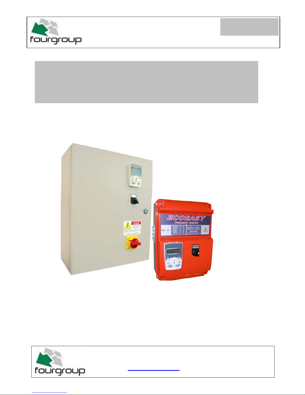
The purpose of this manual is to provide the necessary information for the proper
installation, use and maintenance of SC/1-TA. The user should read this manual before
operating the unit. Improper use may cause damage to the machine and lead to the
forfeiture of the warranty coverage. Always specify the model identification code and the
construction number when requesting technical information or spare parts from our Sales
and Service department. The instruction and warnings given below concern the standard
version; refer to the sale contract documentation for modifications and special version
characteristics. For instructions, situations and events not considered in this manual or in
the sale documents, please contact our customer service.
Our units must be installed in sheltered, well-ventilated, non-hazardous environments and
must be used at a maximum temperature of +40°C and minimum of -5°C.
DANGER
WARNING
The panel must be handled with care, as falls and knocks can cause damage without any
visible external signs.
If for any reason the unit is not installed and starter immediately after it has reached its
destination it must be stored properly. The external packaging and the separately packed
accessories must remain intact, and the whole must be protected from the weather,
especially from freezing temperatures, and from any knocks or falls.
PRELIMINARY INSPECTION: after you have removed the external packaging, visually
inspect the control panel to make sure it has suffered no damage during shipping.
If any damage is visible, inform a FOURGROUP dealer as soon as possible, no later then
five days from the delivery date.
FOURGROUP S.r.l. shall not be liable for any damage caused or suffered by the
unit as a result of its unauthorised or improper use.
2. OVERVIEW
3. HANDLING

4
-Position the AUT-0-MAN selector switch on “0” and the
keypad should display
-Enter the programming menu and press “MENU”
-The following will be displayed on the keypad:
REM 0.0 Hz
DIR MENU
0.0 Hz
0.0 A
0.0 bar
REM MAIN MENU---------1
EXIT ENTER
PARAMETERS-----
ASSISTANTS
CHANGED PAR
4. PROGRAMMING THE ABB-ACS INVERTER WITH THE
PANEL ASSISTANT

5
-Press “ENTER” and the keypad should display:
-With the up arrow select the family
“-99 START UP DATA-“ the keypad should display:
-Press “SELECT” and the keypad should display:
REM PAR GRUOPS--------01
EXIT SEL
01 OPERATING DATA_ _____
03 FB ACTUAL SIGNALS
04 FAULT HISTORY
10 START/STOP/DIR
11 REFERENCE SELECT
REM PAR GRUOPS--------99
EXIT SEL
99 START-UP DATA ----
01 OPERATING DATA
03 FB ACTUAL SIGNALS
04 FAULT HISTORY
10 START/STOP/DIR
REM PARAMETERS-------
EXIT EDIT
9901 LANGUAGE---------//…/----
---------------ENGLISH-/////////--------
9902 APPLIC MACRO
9903 MOTOR TYPE
9904 MOTOR CTRL MODE

6
-With the down arrow select the parameter
“9905 MOTOR NOMINAL VOLTAGE“ and the keypad should display:
-Press “EDIT” and check that the correct power voltage (Volt) of
the motor appears on the keypad.
- To change the value press the up or down arrows
Set the required value and press “SAVE”
and the keypad should display:
Ex. motor 230V Ex. motor 400
V
REM PARAMETERS-------
EXIT EDIT
9902 APPLIC MACRO
9903 MOTOR TYPE
9904 MOTOR CTRL MODE
9905 MOTOR NOM VOLT ---
-------------- … … V… .… .---- ---
REM PAR EDIT--------------
CANCEL SAVE
9905 MOTOR NOM VOLT
230V
REM
CANCEL SAVE
9905 MOTOR NOM VOLT
400V
REM PARAMETERS-------
EXIT EDIT
9902 APPLIC MACRO
9903 MOTOR TYPE
9904 MOTOR CTRL MODE
9905 MOTOR NOM VOLT ---
----- .230 / 400 V… .….---- ---
PAR EDIT--------------

7
-With the down arrow select the parameter
“9906 MOTOR NOMINAL CURRENT“ and the keypad should display:
-Press “EDIT” and check that the correct absorption current (A) of
the motor appears on the keypad.
Example 4A motor:
- To change the value press the up or down arrows
Set the required value and press “SAVE” and the keypad
should display:
REM PARAMETERS-------
EXIT EDIT
9903 MOTOR TYPE
9904 MOTOR CTRL MODE
9905 MOTOR NOM VOLT
9906 MOTOR NOM CURR .-- .
………… . .… A ….…
REM
CANCEL SAVE
9906 MOTOR NOM CURR
4.0 A
PAR EDIT--------------
REM PARAMETERS-------
EXIT EDIT
9903 MOTOR TYPE
9904 MOTOR CTRL MODE
9905 MOTOR NOM VOLT
9906 MOTOR NOM CURR . .
------- 4.0 A //////////…

8
-With the down arrow select the parameter
“9907 MOTOR NOMINAL FREQ.“ and the keypad should display:
-Press “EDIT” and check that the correct nominal frequency
(Hz) of the motor appears on the keypad.
Example 50Hz motor:
- To change the value press the up or down arrows
Set the required value and press “SAVE” and the keypad
should display:
REM PARAMETERS-------
EXIT EDIT
9904 MOTOR CTRL MODE
9905 MOTOR NOM VOLT
9906 MOTOR NOM CURR
9907 MOTOR NOM FREQ////////.
…………… 50 Hz //////////////////.
REM
CANCEL SAVE
9907 MOTOR NOM FREQ
50.0 Hz
PAR EDIT---------------
REM PARAMETERS-------
EXIT EDIT
9904 MOTOR CTRL MODE
9905 MOTOR NOM VOLT
9906 MOTOR NOM CURR
9907 MOTOR NOM FREQ////////.
…………… 50 Hz //////////////////.

9
-With the down arrow select the parameter
“9908 MOTOR NOMINAL SPEED“ and the keypad should display:
-Press “EDIT” and check that the correct rpm (rpm o min-1) of
the motor appears on the keypad.
Example 2900rpm motor:
- To change the value press the up or down arrows
Set the required value and press “SAVE” and the keypad
should display:
ENTER
REM PARAMETERS-------
EXIT EDIT
9905 MOTOR NOM VOLT
9906 MOTOR NOM CURR
9907 MOTOR NOM FREQ
9908 MOTOR NOM SPEED///// .
………… 2900 rpm...//////////////..
REM
CANCEL SAVE
9908 MOTOR NOM SPEED
2900 rpm
PAR EDIT-----------------
REM PARAMETERS-------
EXIT EDIT
9905 MOTOR NOM VOLT
9906 MOTOR NOM CURR
9907 MOTOR NOM FREQ
9908 MOTOR NOM SPEED .
………… 2900 rpm....……....

10
-With the down arrow select the parameter
“9909 MOTOR NOMINAL POWER“ and the keypad should display:
-Press “EDIT” and check that the correct nominal power (KW) of
the motor appears on the keypad.
Example 1.5Kw motor:
- To change the value press the up or down arrows
Set the required value and press “SAVE” and the keypad
should display:
REM PARAMETERS-------
EXIT EDIT
9906 MOTOR NOM CURR
9907 MOTOR NOM FREQ
9908 MOTOR NOM SPEED
9909 MOTOR NOM POWER/////
…………… 1.5 KW/////////////////.
REM
CANCEL SAVE
9909 MOTOR NOM POWER
1.5 KW
PAR EDIT-----------------
REM PARAMETERS-------
EXIT EDIT
9906 MOTOR NOM CURR
9907 MOTOR NOM FREQ
9908 MOTOR NOM SPEED
9909 MOTOR NOM POWER////.
…………… 1.5 KW //////////////.

11
-Press the “EXIT” key once to return to the list of families and the
keypad should display:
-With the down arrow select the family
“40 PID SET1 CHECK“ and the keypad should display:
-Press “SELECT” and the keypad should display:
REM PAR GROUPS--------99
EXIT SEL
99 START-UP DATA ----
01 OPERATING DATA
03 FB ACTUAL SIGNALS
04 FAULT HISTORY
10 START/STOP/DIR
REM PAR GROUPS-------40
EXIT SEL
33 INFORMATION
34 PANEL DISPLAY
35 MOTOR TEMP MEAS
36 TIMED FUNCTIONS
40 PROCESS PID SET 1 .---
REM PARAMETERS-------
EXIT EDIT
4001 GAIN ------- /////////////--
--------------- 4.0 ---------.….--
4002 INTEGRATION TIME
4003 DERIVATION TIME
4004 PID DERIVE FILTER

12
-With the down arrow select the parameter
“4009 100% VALUE“ and the keypad should display:
-Press “WRITE” and on the keypad use the arrows to
change the parameter according to the maximum range of the pressure
sensor (bar).
Example 0-10bar sensor:
-To save the modified parameter press “SAVE” and the keypad
should display:
REM PARAMETERS-------
EXIT EDIT
4006 UNITS
4007 UNITS SCALE
4008 0% VALUE
4009 100% VALUE /////////-
-------------- 10.0 bar…//////////////-
REM
CANCEL SAVE
4009 100% VALUE
10.0 bar
PAR EDIT---------------
REM PARAMETERS---------
EXIT EDIT
4006 UNITS
4007 UNITS SCALE
4008 0% VALUE
4009 100% VALUE /////////////////
-------------- 10.0 bar///////////////////

13
-With the down arrow select the parameter
“4011 INTERNAL SET POINT “ and the keypad should display:
-Press “EDIT” and on the keypad use the arrows to
change the parameter according to the nominal pressure (bar) to be
maintained in the system.
Example 4bar pressure:
-To save the modified parameter press “SAVE” and the keypad
should display:
REM PARAMETERS-------
EXIT EDIT
4008 0% VALUE
4009 100% VALUE
4010 SET POINT SEL
4011 INTERNAL SETPNT -/////-
-------------- … 5.0 bar..//////////////-
REM
CANCEL SAVE
4011 INTERNAL SETPNT
4.0 bar
PAR EDIT---------------
REM PARAMETERS-------
EXIT EDIT
4008 0% VALUE
4009 100% VALUE
4010 SET POINT SEL
4011 INTERNAL SETPNT////////-
-------------- … 4.0 bar//////////-/// -

14
-With the down arrow select the parameter
“4023 PID SLEEP LEVEL“ and the keypad should display:
-Press “EDIT” and on the keypad use the arrows to change
the parameter to a frequency of 00.0Hz and the keypad should display:
-To save the modified parameter press “SAVE” and the keypad
should display:
EXIT
EXIT
REM PARAMETERS-------
EXIT EDIT
4020 ACT2 MINIMUM
4021 ACT2 MAXIMUM
4022 SLEEP SELECTION
4023 PID SLEEP LEVEL- -
-------------- 40.0 Hz… .….------ -
REM
CANCEL SAVE
4023 PID SLEEP LEVEL
00.0Hz
PAR EDIT---------------
REM PARAMETERS-------
EXIT EDIT
4020 ACT2 MINIMUM
4021 ACT2 MAXIMUM
4022 SLEEP SELECTION
4023 PID SLEEP LEVEL- -
-------------- 00.0 Hz… .….------ -

15
-Press “EXIT” three times to return to the first page and the
keypad should display:
- Close all utilities to pressurise the entire hydraulic system.
-Position the AUT-0-MAN selector switch on “AUT” and
check that the Hz value increases on the keypad
REM 0.0 Hz
DIR MENU
0.0 Hz
0.0 A
0.0 bar

16
-Check on the keypad that the value reaches the nominal pressure set
previously (in this case 4bar as set for parameter 4011) and that the
keypad displays:
-Once the system reaches the nominal pressure and therefore is
entirely pressurised allow the pump to run for about one minute;
-Check that the system’s frequency value stabilises (in this case 35Hz).
-Position the AUT-0-MAN selector switch on “0” and the
keypad should display:
REM 0.0 Hz
DIR MENU
50.0 Hz
3.9 A
4.0 bar
REM 0.0 Hz
DIR MENU
35.0 Hz
2.5 A
4.0 bar
REM 0.0 Hz
DIR MENU
0.0 Hz
0.0 A
4.0 bar

17
-Enter the programming menu and press “MENU”
-The following should be displayed on the keypad:
-Press “ENTER” and the keypad should display:
-With the down arrow select the family
“40 PID SET1 CHECK“ and the keypad should display:
ENTER
REM MAIN MENU---------1
EXIT ENTER
PARAMETERS---.-
ASSISTANTS
CHANGED PAR
REM PAR GROUPS-------01
EXIT SEL
01 OPERATING DATA_ _____
03 FB ACTUAL SIGNALS
04 FAULT HISTORY
10 START/STOP/DIR
11 REFERENCE SELECT
REM PAR GROUPS------40
EXIT SEL
33 INFORMATION
34 PANEL DISPLAY
35 MOTOR TEMP MEAS
36 TIMED FUNCTIONS
40 PROCESS PID SET 1……..

18
-Press “SELECT” and the keypad should display:
-With the down arrow select the parameter
“4023 PID SLEEP THRESHOLD“ and the keypad should display:
-Press “WRITE” and on the keypad use the arrows to
change the parameter to a frequency 2 or 3Hz higher than the previous
reading (in this case 35Hz+3Hz=38) see page 16 (second step) and
check that the keypad displays:
REM PARAMETERS-------
EXIT EDIT
4001 GAIN ------- …--
--------------- 4.0 ---------….--
4002 INTEGRATION TIME
4003 DERIVATION TIME
4004 PID DERIVE FILTER
EXIT
REM PARAMETERS-------
EXIT EDIT
4020 ACT2 MINIMUM
4021 ACT2 MAXIMUM
4022 SLEEP SELECTION
4023 PID SLEEP LEVEL- -
-------------- 00.0 Hz … .….------ -
REM
CANCEL SAVE
4023 PID SLEEP LEVEL
38.0Hz
PAR EDIT--------------

19
-To save the modified parameter press “SAVE” and the keypad
should display:
-Press “EXIT” three times to return to the first page and the
keypad should display:
-The system is ready for use.
EXIT
EXIT
REM
4023
PAR FWD
ENTER
REM PARAMETERS-------
EXIT EDIT
4020 ACT2 MINIMUM
4021 ACT2 MAXIMUM
4022 SLEEP SELECTION
4023 PID SLEEP LEVEL-/////////-
-------------- 38.0 Hz /////////////////-
REM 0.0 Hz
DIR MENU
0.0 Hz
0.0 A
4.0 bar

20
N.B. : TO WORK CORRECTLY THE SYSTEM MUST BE IN REMOTE
MODE (REM top left).
Press the LOC/REM key to switch from REMOTE (REM) to LOCAL
(LOC) and vice versa.
When the inverter is in LOC mode all automatisms are excluded and
the inverter will remain in stand-by even if the pressure goes down.
PRESS the LOC/REM key once to switch the system back to REMOTE
(REM).
CAUTION!!! RESETTING PROGRAMMING FUNCTION (contact the
technical office before carrying out the operation)
1. Position the SA1 selector of the “AUT-0-MAN” control on “0”.
2. Use the “loc rem” key of the acs control to switch from “remote” to “local”
control ( “loc” will appear on the top left of the display).
3. Press “SELECT”, scroll using the ↑,↓arrows to display “backup par”.
4. Press “SELECT” to select.
5. Scroll using the ↑,↓arrows to display “unload all to acs”.
6. Confirm again with “SELECT” and wait for the acs programming to reset
(during the procedure the display will show the loading % of programming)
7. The display will show “parameter download operation successful”. Press ok.
8. Press “EXIT” twice to return to the main page.
9. Use the “Loc Rem” key on the panel to switch the acs control to remote for
standard operation (“rem” will appear on the top left of the display.)
REM 0.0 Hz
DIR MENU
0.0 Hz
0.0 A
4.0 bar
This manual suits for next models
1