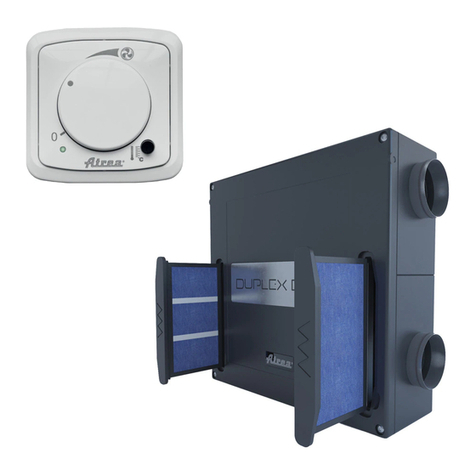
ATREA DUPLEX RA5 User manual

1
EN
Version: 07
Issue: 2021_09
Code: R29_V07_2021_09
DUPLEX RA5, RB5, RK5

2
1. General information, glossary of terms
1.1 Sections of the manual
1.2 Table of contents
1. General information, glossary of terms............................................................................................................................. 2
1.1 Sections of the manual..................................................................................................................................................... 2
1.2 Table of contents.............................................................................................................................................................. 2
1.3 Introduction ...................................................................................................................................................................... 4
1.4 Description of the unit ...................................................................................................................................................... 4
1.5 Abbreviations, marking..................................................................................................................................................... 4
1.6 Important information ....................................................................................................................................................... 4
1.7 Intended scope of application .......................................................................................................................................... 5
2. Scope of supply, accessories, transportation and storage ............................................................................................... 5
2.1 Storage and transportation............................................................................................................................................... 5
2.2 Scope of supply................................................................................................................................................................ 5
2.3 Mandatory accessories .................................................................................................................................................... 6
2.4 Optional accessories........................................................................................................................................................ 6
Integrated heating or cooling coils........................................................................................................................... 6
External, duct air pre-heaters .................................................................................................................................. 6
Other accessories.................................................................................................................................................... 6
Selecting a suitable air conditioner for DUPLEX R5 units........................................................................................ 6
3. Description and technical data ......................................................................................................................................... 7
3.1 Technical parameters....................................................................................................................................................... 7
3.2 Description of main components of Duplex R5 units........................................................................................................ 8
Drawing and description of main components of DUPLEX RA5 units ..................................................................... 8
Drawing and description of main components of DUPLEX RK5 units ..................................................................... 9
Drawing and description of main components of DUPLEX RB5 units ................................................................... 10
3.3 Configuration options 10 / 11 for RA5 and RK5 units..................................................................................................... 11
3.4 Optional configurations of RB5 units .............................................................................................................................. 12
3.5 Descirption of air filters................................................................................................................................................... 13
4. Unit assembly and installation ........................................................................................................................................ 13
4.1 Installation of R5 units.................................................................................................................................................... 13
4.2 Fitting a reducer in RB5 units......................................................................................................................................... 15
4.3 Changing the position of the recirculated air fan outlet in RB5 units .............................................................................. 15
4.4 Connecting the condensate drain................................................................................................................................... 16
General condensate drain arrangmenet in DUPLEX R5 units............................................................................... 16
Connecting the condensate drain line in DUPLEX R5 units .................................................................................. 17
4.5 Wiring and cable entry point........................................................................................................................................... 17
4.6 Connecting the hot water coil......................................................................................................................................... 18
General information, glossary of terms
Commissioning, warranty
Scope of supply, accessories, transportation
and storage
Maintenance and servicing
Description of the unit, technical data
Troubleshooting
Assembly and installation
Appendices
Instrumentation and control, electrical wiring

3
4.7 Connecting the integrated electric heater....................................................................................................................... 18
4.8 Connecting the cold water coil ....................................................................................................................................... 18
4.9 Connecting the direct evaporator / condenser ............................................................................................................... 18
4.10 Installing the zone damper in the bottom outlet in RA5 and RK5 units........................................................................... 19
4.11 Installing controllers ....................................................................................................................................................... 19
CP Touch controller............................................................................................................................................... 20
5. Instrumentation and control, electrical wiring.................................................................................................................. 21
5.1 RD5 control system with CP Touch controller................................................................................................................ 21
Connecting the controller to the unit ...................................................................................................................... 21
Starting the display ................................................................................................................................................ 22
Symbols and their meaning ................................................................................................................................... 23
Symbols on the main screen ................................................................................................................................. 23
Navigation symbols ............................................................................................................................................... 24
Symbols permanently displayed on the main screen............................................................................................. 24
“Power” block......................................................................................................................................................... 24
Power settings in recirculated air mode................................................................................................................. 24
“Mode” block.......................................................................................................................................................... 25
List of modes ......................................................................................................................................................... 25
“Temperature” block ............................................................................................................................................. 26
“Zone” block........................................................................................................................................................... 26
User settings.......................................................................................................................................................... 26
Parameters ............................................................................................................................................................ 26
Control................................................................................................................................................................... 26
Přepnutí HS/NHS .................................................................................................................................................. 26
HS/NHS temperature............................................................................................................................................. 27
Current season ...................................................................................................................................................... 27
Control settings...................................................................................................................................................... 27
IN1 input blocking (No/HS /NHS).......................................................................................................................... 27
IN2 input blocking (No/HS /NHS).......................................................................................................................... 27
Heating hysteresis ................................................................................................................................................. 27
Cooling hysteresis ................................................................................................................................................. 27
Bank holidays ........................................................................................................................................................ 27
School holidays ..................................................................................................................................................... 28
Holiday / Party ....................................................................................................................................................... 28
Setting the weekly program ................................................................................................................................... 29
Copying days......................................................................................................................................................... 29
Network settings .................................................................................................................................................... 30
Texts...................................................................................................................................................................... 30
Display settings ..................................................................................................................................................... 30
Time zone setting .................................................................................................................................................. 30
Daylight saving time .............................................................................................................................................. 31
SW information ...................................................................................................................................................... 31
Filter replacement indication.................................................................................................................................. 31
Table of alarms and notifications ........................................................................................................................... 31
Forgetful operator .................................................................................................................................................. 33
Bypass dampers.................................................................................................................................................... 33
5.2 Control system RD5 with CP Touch controller ............................................................................................................... 33
5.3 Commissioning............................................................................................................................................................... 34
Connecting to the mains power supply................................................................................................................. 34
Required protection and mains power supply connection ..................................................................................... 34
Connecting and installing sensors ......................................................................................................................... 34
5.4 Warranty ........................................................................................................................................................................ 34
6. Maintenance and service ............................................................................................................................................... 34
6.1 Maintenance and service ............................................................................................................................................... 34
6.2 Replacing G4/F7 air filters – fabric version .................................................................................................................... 34
Replacement and cleaning of the ODA pre-filter – expanded metal ...................................................................... 35
Replacement and cleaning of ODA and ETA fabric filters ..................................................................................... 35
Replacement and maintenance of the main fabric filter for RCA units................................................................... 36
6.3 Cleaning the plastic heat recovery exchanger ............................................................................................................... 39
Sliding out the heat recovery exchanger from RB5 units....................................................................................... 39
Sliding out the heat recovery exchanger from RA5 and RK5 units........................................................................ 39
6.4 Cleaning controllers ....................................................................................................................................................... 39
6.5 Cleaning other parts of the unit – minor maintenance.................................................................................................... 39
6.6 Spare parts, repairs........................................................................................................................................................ 40

4
6.7 Breakdowns, safety instructions..................................................................................................................................... 40
7. Faults and troubleshooting ............................................................................................................................................. 41
7.1 Faults and troubleshooting............................................................................................................................................. 41
8. Appendices..................................................................................................................................................................... 42
8.1 Product data sheet......................................................................................................................................................... 42
8.2 RD5 wiring diagram – internal wiring.............................................................................................................................. 43
8.3 RD5 wiring diagram - optional accessories ................................................................................................................... 44
1.3 Introduction
The manual is intended solely for ATREA’s DUPLEX RA5, RB5 and RK5 balanced-pressure recirculating ventilation units including
built-in RD5 control modules and a heat / cold exchanger.
1.4 Description of the unit
It is a compact, recirculating ventilation unit with a heat recovery feature and built-in exchangers. The unit consists of a casing,
a pair of fans, a heat recovery exchanger, heating and cooling exchangers, a built-in control module, a bypass damper,
a recirculating air damper, filters, thermostats and sensors.
DUPLEX RA5 –units designed for free-standing installation only; duct connection collars must be specified
DUPLEX RB5 – units designed for ceiling-suspended installation only; versatile configuration
DUPLEX RK5 –units designed for free-standing installation only; duct connection collars must be specified
Collectively, this group of units is referred to as DUPLEX R5.
1.5 Abbreviations, marking
ODA (e1)
- Supply of fresh air from the outside into the unit
SUP (e2+c2)
- Supply of fresh air after heat recovery into the building or supply of thermally conditioned recirculated air back
into the building
ETA (i1)
- Intake of waste air from the building into the unit
EHA (i2)
- Waste air exhaust from the unit to the outside
RCA (c1)
- Intake of recirculated air into the unit for thermal conditioning
VZT
- HVAC
1.6 Important information
• DUPLEX heat recovery ventilation units are designed for comfort ventilation, heating and cooling in standard environments
(CSN 33 2000-5-51) with relative humidity up to 90%. If the unit should be used for different purposes (e.g. drying newly
constructed buildings, dust extraction etc.) or not operated in keeping with the instructions contained in the use and
maintenance manual, the producer shall not be held liable for any resulting damage.
• The units may only be installed indoors within the heat envelope of residential buildings.
• Only adults sufficiently familiar with the “Installation, use and maintenance manual” may operate the unit.
• The user must not tamper with or modify any part of the unit, particularly the power supply lines! The unit must not be used
for drying construction sites or for dust, building material or other solid particle extraction.
• Only professional service technicians with relevant qualifications may perform the commissioning and repairs of the unit.
Unprofessional maintenance and repairs are very risky and may result in loss of warranty.
• Every time before opening the unit’s door in order to perform cleaning, replace filtration fabric or carry out basic mainte-
nance make sure the unit is disconnected from the power supply and ensure it cannot be reconnected by another person.
• Air ductwork of at least 2 metres in length must be attached to the unit on the fan discharge side as a means of protection
against injury caused by the fan wheel. This ductwork must be attached to the unit in such a way so it can only be removed
by using tools.
• The unit may only be installed in places where temperature does not drop below 10 °C and relative humidity is up to 60 % at
20 °C.
• If the unit has been out of operation for a prolonged period of time, extra care should be taken when putting it back into
operation.
• The unit – intended for standard environments – may be operated within a ventilation air temperature range of between
-25 °C and 45 °C and relative humidity up to 90%, in an environment where there is no risk of fire or explosion of flammable
gases or fumes containing organic solvents or corrosive substances that might damage mechanical parts of the unit. If there
is a danger of such gases and fumes temporarily entering the tube system (e.g. during floor bonding, painting), the unit must
be switched off sufficiently ahead of time.
• Electrical connections, commissioning and adjustment of the unit may only be carried out by appropriately qualified electrical
engineers. The unit must be protected using a 1×10 A char. C circuit breaker.
• If additional protection against touching active and inactive parts is provided by a residual-current circuit breaker, a special
residual-current device designed for circuits with frequency converters and switched-mode power supplies must be used. It
is a circuit breaker sensitive to alternating, pulse and residual currents and resistant to current surges of up to 5 kA

5
• Before the installation and commissioning of the unit carefully read the installation, use and maintenance manual.
• The unit and all of its accessories must be installed and used in compliance with the design, technical conditions specified
by the manufacturer and applicable legislation and technical standards in effect.
• The unit may not be installed and operated in a corrosive environment that could damage its external and internal
mechanical parts.
• Before putting the unit into permanent operation an initial inspection report on the appliance´s power supply must be
provided and a report on commissioning and operator training must be completed.
• In the event of failure, the unit must be disconnected from the power supply as soon as possible!
• When handling the unit observe all safety rules (including safe work at heights and work with suspended loads) and use
suitable work and protective equipment.
• Make sure the casing of the unit is not damaged or deformed during installation.
• Units fitted with a hot water coil (optional accessory) must be permanently connected to the power supply to make sure frost
protection is provided for the coil. If the power supply should be turned off for a prolonged period of time, the heating
medium must be drained from the coil. We recommend draining the medium using pressurised air, not gravity!
• The RJ45 connector for connecting to an Ethernet network must not be connected to a network using a PoE (Power over
Ethernet) technology.
The manufacturer is not liable for damage caused by improper installation of the unit which fails to
comply with the installation manual and general principles applied in installing air handling units and
control systems.
1.7 Intended scope of application
DUPLEX R5 heat recovery ventilation units are designed for comfort ventilation, heating and cooling; they are intended solely for
residential premises – houses and flats. They can also be used in residential buildings, offices, schools, hotels and small facilities.
If the unit is used for other purposes or not in keeping with the instructions for use and maintenance, the manufacturer is not liable
for any resulting damage.
2. Scope of supply, accessories, transportation and storage
2.1 Storage and transportation
•The unit may only be stored in dry, covered places with ambient temperatures between 0 and 50 °C. Units must not be
stacked on top of each other and must be placed on a flat and hard surface to prevent any damage to the unit or its
packaging.
•During storage the units must remain in their original, intact packaging including all spacing, tying and marking features.
•The transportation packaging may not be removed until immediately before the installation on site. Before installation the site
must be checked for cleanliness. In addition, the switchboard must be checked for cleanliness and good condition and
cleaned as necessary.
•During transportation the unit must be protected against falling, mechanical damage, water penetration and other adverse
conditions which might damage the unit or its packaging.
2.2 Scope of supply
The full set always contains a specified type AHU, an RD5-series integrated control system, a pair of basic G4 filters, a condensate
drain kit (a flexible hose and reducers for connection to the designated point on the unit), an operation and maintenance manual
and an energy label for the product.
DUPLEX R5 scope of supply
An AHU type as
specified including
filters
Condensate drain
pipework
connection kit
Operation and
installation manual,
technical data
Energy label
Outside
temperature
sensor
(ADS 110)
Reducer from
110×295 to D 200
(only in RB5 units)

6
2.3 Mandatory accessories
With this type of the unit it is necessary to install a room temperature sensor in your premises to facilitate its cooling and heating
function. The following can be used as this sensor:
•A sensor integrated in a CP Touch controller
•External temperature sensor ADS ABB
2.4 Optional accessories
Air heating or cooling coils can be connected to the unit. In addition, electric pre-heaters or integrated shut-off dampers can be
used with RA5 and RK5 units. For designing your unit including accessories use ATREA’s own selection software.
Integrated heating or cooling coils
Modification T.3
An integrated hot water coil for heating supply air, always configured for a particular type of the
unit.
Modification E An integrated electric heater for heating supply air, always configured for a particular type of the
unit. Its power is specified in the table of technical parameters.
Modification CHW An integrated cold water coil for cooling supply air, always configured for a particular type of the
unit. An option to select between a 3-row or 5-row type.
Modification CHF An integrated refrigerant coil for cooling or heating supply air, always configured for a particular
type of the unit.
External, duct air pre-heaters
EPO-V An electric duct heater for pre-heating air; its type is specific for the type of the unit.
Other accessories
CP Touch controllers A wall-mounted touch-screen controller for comprehensive control.
RA5/RK5 zone damper Intended for closing the bottom air outlets of 200×50floor channels.
Only for RA5 and RK5 units and for installation in 628×476 or 832×476mm plenums. .
FG09 outdoor unit An outdoor air conditioner for heating and cooling, a suitable unit as specified in chapter 2.43.
A CIM module must also be specified to provide power control.
FG14 outdoor unit An outdoor air conditioner for heating and cooling, a suitable unit as specified in chapter 2.43.
A CIM module must also be specified to provide power control.
FG18 outdoor unit An outdoor air conditioner for heating and cooling, a suitable unit as specified in chapter 2.43.
A CIM module must also be specified to provide power control.
Selecting a suitable air conditioner for DUPLEX R5 units
DUPLEX R5 unit type
RB5
RA5
RK5
Recirculated air flow rate
[m3/h]
˂600
˂600
˂1000
Suitable air conditioner
Unit type
[-]
FG09
FG14
FG18
Refrigerant type
R32
R410A
R410A
CHF evaporator in
DUPLEX unit
Dimensions for fluid
[mm]
6.1
6.1
6.1
Dimensions for gas
10.1
12.1
12.1
Register type
[-]
CHF RB3
CHF RA3
CHF RK3
Evaporator type
[-]
1
2
2
Number of rows
[-]
3R
3R
3R

7
3. Description and technical data
3.1 Technical parameters
DUPLEX unit identification
RA5
RB5
RK5
Ordering code
A170421
A170431
A170441
Energy label
A1)
A1)
A1)
Control system
RD5.CF
Outside air temperature sensor (ADS 110)
Included
Main power supply
Connecting voltage
[V]
230 V / 50 Hz
230 V / 50 Hz
230 V / 50 Hz
Required protection
[A]
1×10 A char. C
1×10 A char. C
1×10 A char. C
Heat recovery
exchanger
Type
[-]
S3.B
S3.B
S3.B
Efficiency (dry)
[%]
78
79
78
Block height
[mm]
275
275
275
Fans
Supply
Type
[-]
M106
M106
M107
Recirculation air flow
rate
(max. power)
[m3/h]
600 m3/h
600 m3/h
1200 m3/h
Power input for sizing
[W]
170 W
170 W
385 W
Exhaust
Type
M104
M104
M104
Ventilation flow rate
(max. power)
[m3/h]
350 m3/h
350 m3/h
350 m3/h
Power input for sizing
[W]
120 W
120 W
120 W
Design
Dimensio
ns
Height
[mm]
1720
1180
1720
Width
[mm]
675
900
865
Depth
[mm]
630
380
630
Duct
connectio
n collars
SUP-top (e2)
[mm]
Ø200
Ø200 (110x295)
Ø250
SUP-bottom (e2)
[mm]
460×460
-not included-
460×460
ODA (e1)
[mm]
Ø200
Ø200
Ø250
ETA (i1)
[mm]
Ø160
Ø160
Ø160
EHA (i2)
[mm]
Ø160
Ø160
Ø160
RCA (c1)
[mm]
Ø200
Ø200
Ø250
Weight with 1 exchanger
[kg]
115
87
125
Weight with 2 exchanger
[kg]
125
97
135
Integrated exchanger
(heating)
Hot water coil, 3 rows (T.3) [-]
TRA 3R / typ1
(20-322501)
TRB 3R / typ1
(20-322103)
TRK 3R / type
1
(20-322501)
Electric heater (E) [-]
ELO PTC RA
6600 W / 400 V
(separate
protection)
ELO PTC RB
4400 W / 400 V
(separate
protection)
ELO PTC RK
6600 W / 400 V
(separate
protection)
Integrated exchangers
(cooling)
Water coil, 3 rows (CHW.3)
[-]
WRA 3R / type 1
WRB 3R / type 1
WRK 3R / type
1
Water coil, 5 rows (CHW.5)
[-]
WRA 5R / type 1
WRB 5R / type 1
WRK 5R / type
1
Direct heat exchanger, 3 rows
(CHF)
[-]
CHF RA3
CHF RB3
CH RK3
Duct exchangers
(heating)
Electric heater (EPO-V)
[-]
EPO-V 200/2,1
EPO-V 200/2,1
EPO-V 250/3,0
[-]
EPO-V 250/3,0
EPO-V 250/3,0
EPO-V 315/6,0
Electric pre-heater (EPO-V)
[-]
EPO-V 160/1,6
EPO-V 160/1,6
EPO-V 160/1,6
Cold / heat source
(condensation unit)
Recommended type
FG14
FG09 / FG14
FG14 / FG18
Power supply and recommended
protection
230 V / 16 A
230 V / 16 A
230 V / 16 A
Refrigerant supply
connection
To
condensatio
n unit
12.7×6.35
9.52×6.35 /
12.7×6.35
12.7×6.35
To heat
exchanger
12.1×6.1
10.1×6.1 /
12.1x6.1
12.1×6.1
Refrigerant type
R410A
R32 / R410A
R410A
Cooling / heating capacity
[-]
Selection SW
Selection SW
Selection SW
Filters
Supply air (i.e. RCA + SUP)
G4/F7
G4/F7
G4/F7
Exhaust air (i.e. ETA)
G4
G4
G4
Controller
CP Touch
CP Touch
CP Touch
*) The values must be configured according to the individual capacity graph lines.
1) All control systems integrated in the unit include as a standard feature at least two inputs for connecting electric signals resulting
from human activity such as handling light fixtures or other devices which automatically control the unit’s capacity levels. These
inputs must always be connected; alternatively, other types of sensors must be connected instead (e.g. CO2, VOC and RH).
For the detailed design of individual components use ATREA’s selection software.

8
3.2 Description of main components of Duplex R5 units
Drawing and description of main components of DUPLEX RA5 units
KEY:
1 – Unit’s casing, 30 mm thick
mineral insulation
2 – Cover of the electric panel
containing RD5 control system
terminals
3 – Counter-flow plate heat
exchanger under a metal sheet
cover
4 – Top-entry duct connection
collars (the size depends on the
type of the unit)
5 – Mv motor (exhaust)behind
a partition
6 – MC motor (supply)
7 – Door hinges (on the other side
fitted with clips incl. safety
latches)
8 – Air filter (intake from the
outside)
9 – Air filter (indoor waste air
intake)
10 – Air filter (main filter)
11 – Securing brackets (2)
12 – Recirculating air damper
connected to a Grüner actuator
13 – Bypass damper – connected
to a Belimo actuator
14 – Integrated exchangers – T.3
/ E / CHW.3 / CHW.5 / CHF
15 – Condensate drain outlet –
bottom from cooling, top from the
heat recovery exchanger
16 – Bottom plenum sound
attenuator
17 – Bottom supply duct
connection collar 460×460
18 – Integrated exchanger
connection from the top
19 – Cable entry point incl. an
earth screw

9
Drawing and description of main components of DUPLEX RK5 units
KEY:
1 – Unit’s casing, 30 mm thick
mineral insulation
2 – Cover of the electric panel
containing RD5 control system
terminals
3 – Counter-flow plate heat
exchanger under a metal sheet
cover
4 – Top-entry duct connection
collars (the size depends on the
type of the unit)
5 – Mv motor (exhaust) behind
a partition
6 – MC motor (supply)
7 – Door hinges (on the other side
fitted with clips incl. safety
latches)
8 – Air filter (intake from the
outside)
9 – Air filter (indoor waste air
intake)
10 – Air filter (main filter)
11 – Securing brackets (2)
12 – Recirculating air damper
connected to a Grüner actuator
13 – Bypass damper – connected
to a Belimo actuator
14 – Integrated exchangers –
T.3 / E / CHW.3 / CHW.5 / CHF
15 – Condensate drain outlet –
bottom from cooling, top from the
heat recovery exchanger
16 – Bottom plenum sound
attenuator
17 – Bottom supply duct
connection collar 460×460
18 – Integrated exchanger
connection from the top
19 – Cable entry point incl. an
earth screw

10
Drawing and description of main components of DUPLEX RB5 units
KEY:
1 – Unit’s casing, 30 mm thick
mineral insulation
2 – Cover of the electric panel
containing RD5 control system
terminals
3 – Counter-flow plate heat
exchanger including fixing
material
4 – Duct connection collars (the
size depends on the type of the
unit)
5 – Mv motor (exhaust) behind a
partition
6 – MC motor (supply)
7 – Door hinges (on the other side
fitted with clips incl. safety
latches)
8 – Air filter (intake from the
outside)
9 – Air filter (indoor waste air
intake)
10 – Air filter (main filter)
11 – Suspension lugs (4)
12 – Recirculating air damper
connected to a Grüner actuator
13 – Bypass damper – connected
to a Belimo actuator
14 – Integrated exchangers –
T.3 / E / CHW.3 / CHW.5 / CHF
15 – Condensate drain outlet –
from the door of the unit
16 – Alternative recirculating air
motor position plug
17 – D200 circular duct reducer
18 – Integrated exchanger
connection from the top
19 – Cable entry point incl. an
earth screw

11
3.3 Configuration options 10 / 11 for RA5 and RK5 units
The basic configuration (that is, configuration 0) of RA5 and RK5 units has five circular duct connection collars from the top and one
rectangular connection from the bottom. This configuration can be arranged in a mirror-wise fashion to position 10 or 11 – this must
be specified when ordering as this cannot be done on site.
Configuration 10
Configuration 11
Below are further configuration options. Each modification must be specified when ordering as they cannot be carried out on site.
Duct connection configuration 01 –
bottom outlet C2 from the side
(RA5=D200, RK5=D250)
Duct connection configuration 02 –
without bottom outlet C2
Duct connection configuration 03 –
without top connection collar C2
K1
K2
+-
C2
C1
E1
I1
I2
EL
UT
C2
K1
K2
+
-
C2
C1
E1 I1
I2
EL
UT
C2
K1
K2
+-
2
K1
K2
+-
C2
C1
E1
I1
I2
EL
UT
C1
E1
I1
I2
EL
UT

12
3.4 Optional configurations of RB5 units
There are two basic configurations – 30/0 and 31/0, arranged in a mirror-wise fashion – must be specified when ordering as no
changes are possible on site.
.
Configuration 30/0
Configuration 31/0
The following two configurations can be arranged on site; they are versions with different positions of C2+E2 30/1 and 31/1
connections.
.
Configuration 30/1
Configuration 31/1
The drawings show the unit in a plan view, seen from the ceiling.
C2
C1
E1
I1
I2
K1
K2
RB4
30/0
-+
C2
C1
E1 I1
I2
K1
K2
+-
RB4
31/0
C1
E1
I1
I2
K1
K2
RB4 CHW
30/0
C2
-+
C1
E1 I1
I2
K1
K2
+-
RB4
31/0
C2
31/1

13
3.5 Description of air filters
The units include several filtration stages as a standard feature. The first stage is a pre-filter made of expanded metal, located on
the fresh air intake ODA side. The exhaust air intake ETA duct connection has a frame fabric filter. The main filter is located
upstream of the integrated hot water coils and cooling coils. Filters are supplied in two classes of filtration: G4 – basic (supplied as
a standard feature), F7 – fine filtration (optional accessory).
Exhaust air (waste)
Supply air (recirculated + ventilation)
Frame with fabric –
exhaust air filter
Filter cassette
– exhaust air filter
Expanded metal –
supply air pre-filter
Recirculated air
fabric filter frame
Filter cassette
– recirculated air filter
(basic filtration)
(optional)
(feature of R5 units)
(basic filtration)
(optional)
4. Unit assembly and installation
The assembly and installation of the unit may only be carried out by a special firm trained by ATREA on the category of products in
question. The unit may only be installed within premises designated and specified by this manual.
Always make sure the power supply is disconnected while performing installation!
4.1 Installation of R5 units
DUPLEX R5 units are installed with a condensate drain line already sloped. RA5 and RK5 units have their internal structural
design modified for that purpose. The unit should be installed on a level floor. In RB5 units the sloping is achieved by brackets
attached from the factory with a height difference. This ensures the required sloping of 2% when the unit is installed underneath
a flat ceiling without the need to rearrange the height of the brackets on site.
Distance between securing brackets for RA5 and RK5 units including clearances – if the outlet connection runs
sideways from sound attenuators (unit configuration 01 – see chapter 3.3), a minimum clearance of 400 mm
must be maintained.
Leave a space for condensate
drain connection - min. 150 mm

14
Distance between securing brackets in RB5 including clearances
The unit is suspended using M8 threaded suspension rods, if possible with vibration insulators (available as optional accessory
A160530).
KEY:
1 – Suspension bracket
2 – Threaded rod M8
3 – Vibration insulator – available
as a set under code A160530
4 – M8 washer – part of A160530
5 – Nut M8
K2
K1
C2/1
C1
I1
ceiling
2%
On the side without
the connection ports
4x
∅
12
On the side without
the connection ports

15
4.2 Fitting a reducer in RB5 units
The reducer is supplied as a standard feature.
Before installing the unit, fit the reducer in the appropriate place – the unit’s outlet, and secure using the 4 bolts provided.
4.3 Changing the position of the recirculated air fan outlet in RB5 units
Any changes in the position of the recirculated air fan motor should be made before suspending the unit from the ceiling – i.e. when
it is on the floor.
Loosen the duct connection from the position it was fitted in at
the factory including the C2 reducer – on the long side – 4
bolts.
Remove the cover from the unit’s casing to provide space for
the new position of duct connection C2.
Move the duct connection to the new position – short side. Plug
the original position opening using the panelling provided. Fit
the metal sheet covers.
Secure the components in their new position.

16
4.4 Connecting the condensate drain
The unit must be fitted with a condensate drain.
The condensate drain must be fitted as indicated in the drawings. The condensate drain outlets not in use must remain sealed. The
condensate drain line must include a trap and lead into a sanitary sewer. The trap must be permanently primed with water. After the
unit has been out of operation and then re-commissioned, the trap musts be checked for priming and unobstructed passage. The
condensate drain line must be connected in such a way so that handling the unit does not cause its damage. Before opening the
door of an RB5 ceiling-suspended unit, the condensate drain line(s) must be disconnected.
Everything is described in detail in a separate manual – Condensate drain installation.
General condensate drain arrangement in DUPLEX R5 units
The condensate drain line must include a trap and lead into a sanitary sewer. The trap must be permanently primed with water.
After the unit has been out of operation and then re-commissioned, the trap musts be checked for priming and unobstructed
passage. The dimension of the condensate drain line connection in all DUPLEX R5 units is 2× Ø16/Ø22.
Condensate drain arrangement in RA5 and RK5 units.
Condensate drain arrangement in RB5 units.
Siphon HL 138 with mechanical odor trap
Siphon made of the flexible pipe
A slope
min. 2 %
HL 21
Make a siphon,
secure with
a clasp and fill
the water
Both condensate drains
can be connected to one
outlet behind the siphon!
Drainage
inlet
HL 138
To be fitted only for cooling
- var. CHF, CHW
Always to be
prepared!
Drainage inlet
Drainage inlet
Siphon HL 138 with mechanical odor trap Siphon made of the flexible pipe
Make a siphon,
secure with a clasp
and fill the water
HL 138
HL 21
Flexible pipe to
placed hor
i
zontally
along the unit door
Flexible pipe bracket
Drainage
inlet
A slope
min. 2%
A slope
min. 2%
Flexible pipe bracket
To be fitted only for cooling
- var. CHF,CHW
Drainage
inlet
Drainage
inlet

17
A trap on a flexible hose Close-up of trap attachment using a clip
Connecting the condensate drain line in DUPLEX R5 units
The condensate drain line is fitted identically in all DUPLEX R5 units.
a) Condensate drain from door on side i2 +
condensate drain fittings
b) Condensate drain connection with
a 90° elbow the slide the hose onto
c) Sliding on the hose and securing it
with a clip (supplied by the installer)
Straight condensate drain connection with
a hose connector
Sliding on the hose and securing it with
a clip (supplied by the installer)
Disconnecting the condensate drain
line from the unit
4.5 Wiring and cable entry point
Do not connect the wiring until the unit has been completely mechanically installed and ducts tight-connected. The wiring must be
connected with the power supply switched off.
DUPLEX RA5 and DUPLEX RK5
DUPLEX RB5
K1
K2
+-
C2
C1
E1
I1
I2
UT
EL
EL
EL
EL

18
4.6 Connecting the hot water coil
The hot water coil is an optional accessory for all DUPLEX R5 units. If it is included, it is supplied already installed in the unit in its
position. The maximum permitted temperature of the heating fluid is 55 °C (treated e.g. by mixing primary heating water or from
an automatically controlled source maintaining constant temperature)and operating pressure up to 0.25 MPa. Connection to
the heating system is recommended via a pair of shut-off valves, a filter for mechanical impurities, a visual thermometer and
pressure gauge and heating fittings.
The rigid line is connected to flexible hoses which run out through the unit’s casing and are terminated with a male thread. Before
connecting, remove the plastic covers used to prevent impurities from entering the system. The heating circuit must have a safety
valve and a closed presser vessel. The heat-carrying substance is untreated water, completely freed of air. The recommended
water hardness rate is between 7–12 °dH. If the water is harder, we recommend softening it. If necessary, an antifreeze can be
used as the heat-carrying substance (e.g. ethylene glycol). It is recommended that the supply and return line should be insulated.
Supply (and refill) water should meet in particular the following criteria:
•It must be clear and colourless.
•Its pH must not be lower than 7. If it contains dissolved neutral salts, its pH must be between 8.5 and 9.5. To make it alkaline
it is possible to use sodium hydroxide or sodium phosphate (Na3PO4).
•The content of carbon dioxide in ionic or covalent form must be kept at a minimum.
•The residual hardness of supply water should be lower than 7 mmol/l (at q < 23 kW/m2) and 5 mmol/l (at q > 23 kW/m2).
The water can be softened using sodium phosphate (Na3PO4) or a cation exchanger (in water harder than 7 mmol/l; systems
with large water volume; for electrical and radiation boilers).
•The amount of lime ions in the water must be up to 3.5 mmol/l (at q < 23 kW/m2) and up to 1.8 mmol/l (at q > 23 kW/m2).
•Total CO2up to 75 mg/l (at q < 23 kW/m2) and 10 mg/l (at q > 23 kW/m2)
The exact composition of the refill water is specified in CSN 07 7401 in attached Table 1.
The recommended connection diagrams are shown in a separate document: Recommended CH connections for R5 units
4.7 Connecting the integrated electric heater
The electric heater is an optional accessory for all types of DUPLEX R5 units. If it is included, it is supplied already installed in the
unit in its position. Its size must always match a particular unit and cannot be used interchangeably.
The heater must be connected to 400 V definitive power supply through a dedicated circuit breaking device including a trip coil
according to the recommended wiring diagram, see Appendix 8.2. The cable is connected to the terminals provided in the unit’s
electrical panel.
4.8 Connecting the cold water coil
The cold water coil is an optional accessory for all types of DUPLEX R5 units. If it is included, it is supplied already installed in the
unit in its position. The cold water coil can be filled with water or an antifreeze (e.g. ethylene glycol). The maximum permitted
operating pressure is 0.25 MPa.
4.9 Connecting the direct evaporator / condenser
The cold water coil is an optional accessory for all types of DUPLEX R5 units. If it is included, it is supplied already installed in the
unit in its position. It can be used as cooler or heater.
When connecting the direct cooler observe the instructions of the supplier of your condensation units and ductwork! The evaporator
is filled with inert gas (nitrogen) at the factory. The condensation unit is always supplied with a refrigerant charge.
!Before connecting ductwork to an outdoor condensation unit, remove the valve on the R_5 fluid circuit!
The recommended refrigerant type is R410A or R32 (depending on the condensation unit type – see the table in Chapter
2.43).
a) Most serious harmful effects of a leaked refrigerant on health
•Refrigerant vapours are heavier than air and may displace oxygen
•At atmospheric pressure refrigerant evaporates at -51.6 °C; its fast evaporation can therefore cause frostbites
•The substance can cause arrhythmia
b) Operator duties when a refrigerant leak or a fire is detected
•Unplug the unit from the power socket; when a refrigerant leak is detected, thoroughly air and immediately leave the affected
premises and do not come close to the unit
•Do not use an open flame
•Immediately report the incident to your servicing company and take further measures as per instructions

19
•In the event of fire, any rescue work may only be conducted while using personal protection equipment (safety gloves, eye
protection, a breathing apparatus or mask with filter against organic vapours)
•If necessary, call the numbers shown below:
4.10 Installing the zone damper in the bottom outlet in RA5 and RK5 units
Shut-off dampers for air distribution plenum boxes under RA5 and RK5 units are an optional accessory. They are used to fully close
/ close of supply air to the plenum box under the unit (so-called zoning) as directed by the integrated control system. The set
includes a louvre damper with installation frame, fixing bolts, an actuator and cabling. For installation follow the instructions below.
The damper can only be used in combination with air distribution plenum boxes R111011 (i.e. 628×476) and R111610 (i.e.
832×476).
1. Slide out the sound attenuator from the bottom plenum.
2. The minimum thickness of insulation of 200×50 mm floor channel
must be 70 mm.
3. Slide the shut-off damper into the opening at the bottom
and secure it using the 4 bolts in the holes provided in
the unit’s casing and connect the actuator cables to the
plastic junction box underneath the recirculated air fan
motor (the box is part of the unit).
4. Slide the bottom outlet sound attenuator back in and start the unit.
4.11 Installing controllers
Note: Before installing or removing a controller, disconnect your DUPLEX R5 ventilation unit from the power supply.
Handling a live controller could lead to electrocuting or cause damage to the controller. This applies to all controller types.
Each of the controllers is compatible only with the control system specified. Using them with different control system types may lead
to damage to the unit.
K2
+
-

20
→●←
Press here
68mm
CP Touch controller
The CP Touch controller is used for comprehensive control and programming the unit with RD5-type control systems, a standard
feature of all DUPLEX R5 units. It is supplied for wall mounting. It can be mounted on a standard electrical junction box with
a hole spacing of 68 mm. The controller should be installed on the wall at a height of 1.3 to 1.5 m in a place that is easily
accessible, well-lit and dry, away from heaters or radiant surfaces – it contains an internal thermostat. For connection use
a shielded connecting cable (SYKFY 2×2×0.5). When the controller needs to be further away from the ventilation unit, the cable
must be replaced / extended (up to 25 metres). The controller is installed by a specialist electrical engineer.
The controller is not a mandatory accessory.
Step 1: Before installation dismantle the controller and
remove the front panel from the rear part.
Step 2: Hold the rear part to the appropriate place on the wall
and attach it using screws.
Step 3: Click the front panel with display on to the rear part
mounted on the wall.
Step 4: The controller mounted on the wall.
The box can be pressed together in one
direction only
This manual suits for next models
2
Table of contents
Other ATREA Fan manuals
Popular Fan manuals by other brands

BLAUBERG
BLAUBERG Lux 100 Service instructions

CONCORD
CONCORD 52HED Owner's manual and installation instructions

Home Decorators
Home Decorators Tahiti Breeze AC303-E manual

Evolar
Evolar EVO-CF30MW installation instructions

S&P
S&P TD - ECOWATT TD-160/100 instruction manual

NuAire
NuAire Genie Plus GPE-100 Series Installation and Maintenance