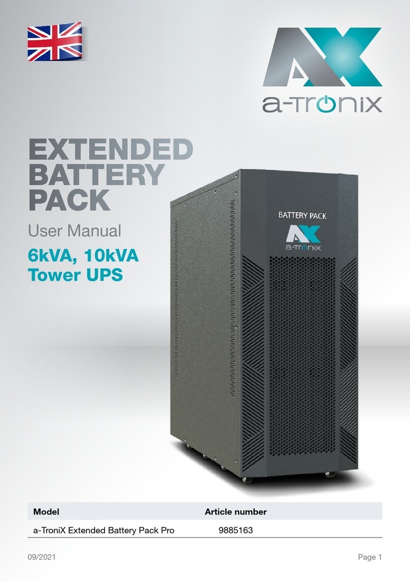
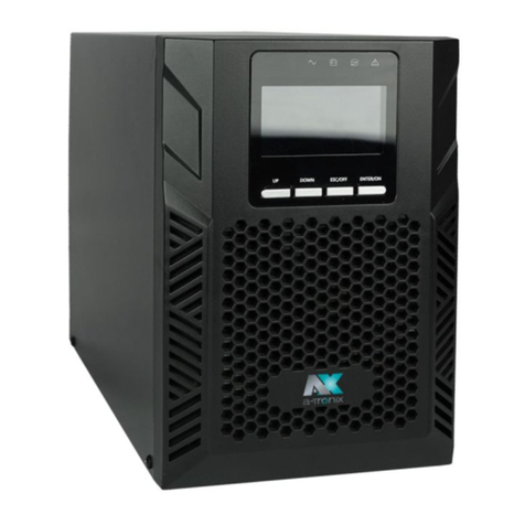
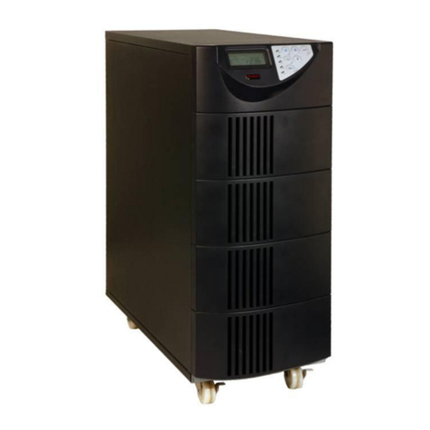
Atronix 9885107 User manual

Model Capacity (VA) Article number
a-TroniX UPS Edition One 6kVA 6000 9885107
a-TroniX UPS Edition One 10kVA 10000 9885108
06/2021 Seite 1
ONLINE UPS
Installation and
Operating Instructions
a-TroniX
UPS Edition One
6kVA, 10kVA

Page 2 06/2021
Installation and Operating Instructions
UPS Edition One 6kVA, 10kVA
INTRODUCTION
The publication and copyright of this documentation remain with the company:
AKKU SYS Akkumulator- und Batterietechnik Nord GmbH
Verbindungsweg 23 · 25469 Halstenbek / Hamburg · GERMANY
Telefon +49 4101 | 3 76 76-0 / Fax +49 4101 | 3 76 76-66
Thank you very much
for purchasing our a-TroniX series online UPS.
It is an intelligent, single-phase, high-frequency online UPS and meets the required safety
standards.
Due to its excellent electrical performance with a power factor of cos phi 1.0, as well as
perfect intelligent monitoring and network functions, it meets the world‘s most advanced
level.
With the a-Tronix Series Edition One, your installations are safely protected from power
supply problems and the functionality of your equipment is maintained.
Read carefully before use
Read this manual carefully before installation.
It contains important regulations and instructions for the use of this product and provides
technical support for the operator of the unit.
All rights reserved
AKKU SYS Akkumulator- und Batterietechnik Nord GmbH cannot be held responsible for
any inaccuracies or inappropriate information in this instruction manual.
The information in this document is subject to change without notice, but there is no
obligation to update it on an ongoing basis.
We reserve the right to make design and equipment changes to improve the production
process or the product. AKKU SYS GmbH accepts no liability for errors in this operating
manual and any consequences resulting therefrom.

06/2021 Page 3
Installation and Operating Instructions
UPS Edition One 6kVA, 10kVA
Table of Contents
Page
1. Important safety instructions 4
1.1 Symbols used in this guide 6
2. Product Introduction 7
2.1 Product view (UPS 6-10 kVA) 7
2.2 The principle of the product 9
2.3 Product Category 9
3. Installation 10
3.1 Unpacking and inspection 10
3.2 Installation Note 10
3.3 UPS input and output connection 11
3.4 Communication cable connection 12
4. Panel display, operation and running 13
4.1 Start up and turn off UPS 13
4.1.1 Start up operation 13
4.1.2 Turn off operation 13
4.2 Faceplate display 14
4.2.1 Faceplate display illumination 14
4.2.2 LCD display 15
4.3 Parameter settings 17
4.3.1 Mode-setting 17
4.3.2 Output voltage class setting 18
4.3.3 Output frequency setting 18
4.3.4 Battery capacity setting 19
4.3.5 Battery quantity setting 19
4.3.6 Bypass Volt-Hi setting 20
4.3.7 Bypass Volt-Lo setting 20
4.3.8 Buzzer Mute Setting 21
4.3.9 Battery Test Setting 21
4.3.10 Parallel ID setting 23
4.3.11 Parallel quantity setting 23
4.3.12 Parallel redundancy quantity setting 24
4.4 Alarm Information 24
5. Maintenance 26
5.1 Battery maintenance 26
6. Troubleshooting 27
7. Specification 28

Page 4 06/2021
Installation and Operating Instructions
UPS Edition One 6kVA, 10kVA
1. Important safety instructions
Be sure to observe all warnings and operating instructions in this manual. Keep this
manual in a safe place and read the following instructions carefully before installing and
operating the unit.
The system may only be installed and connected by trained electricians in compliance
with the relevant safety regulations.
The operating instructions must be read and understood by all personnel and specialists
who are responsible for the operation, cleaning as well as disposal of the unit.
Dangerous voltages and high temperatures are present inside the UPS. Observe the
local safety instructions and the corresponding laws during installation, operation and
maintenance, otherwise personal injury or damage to the unit may occur. The safety
instructions in this manual serve as a supplement to the local safety instructions.
Our company accepts no liability for damage caused by failure to observe the safety
instructions.
The UPS as well as the associated components may only be used for the purpose
corresponding to their design - to supply electrical devices (230 V AC) which in total do
not exceed the rated power. Any other use or use beyond this is considered improper and
may result in personal injury, property damage and/or damage to equipment
Please note the following:
■ Don’t use the UPS when the actual load exceeds the rated load.
■ Internal short circuit of the UPS will cause electric shock or re. So don’t place
the containers equipped with liquid on the top of the UPS so as not to cause
danger of electric shock.
■ Do not place the UPS in a location with high temperature or humidity,
corrosive gases or much dust.
■ Ensure good air circulation between the inlet opening at the front and the
outlet opening at the back to prevent excessive heating.
■ Avoid direct sunlight or the proximity of heat-emitting objects.
■ If smoke appears on the UPS, please switch off the power as soon as possible
and contact your supplier.
■ Work on accumulators is to be carried out and supervised only by personnel
with appropriate expertise in the required safety rules. Unauthorised persons
must be kept away from accumulators.
■ There are high capacity batteries in the UPS. Do not open or destroy them.
The released electrolyte is dangerous for people and the environment. There is
a risk of explosion. If internal maintenance or battery replacement is required,
contact your supplier.

06/2021 Page 5
Installation and Operating Instructions
UPS Edition One 6kVA, 10kVA
■ When changing batteries, always insert the same number and type of
batteries.
■ Batteries or their connections can cause electric shocks.
■ If short circuits occur on batteries, touching the live parts can cause severe
burns.
■ Batteries must never be brought into contact with heat sources or ames.
■ Do not attempt to dispose of the batteries by burning them.
Defective accumulators must be disposed of in an environmentally friendly
manner. Do not throw them in the household waste under any circumstances
and observe the local disposal regulations.
Use the certied and professional recycling service of our AkkuSys team.
For more information, contact us on the order hotline +49 4101/376760,

Page 6 06/2021
Installation and Operating Instructions
UPS Edition One 6kVA, 10kVA
1.1 Symbols used in this guide
In these operating instructions, the abbreviation UPS stands for:
Uninterruptible Power Supply.
Accumulators are usually used as energy storage for a UPS system. These are also
colloquially referred to as accumulators or batteries.
Warnings and notes are indicated by the corresponding symbols (pictograms) and must
be observed:
WARNING!
Warning of dangerous electrical voltage.
General warning of danger points.
Warning when handling accumulators.
NOTE:
This symbol indicates texts, notes or tips. Failure to take precautionary
measures may result in damage to the product and/or its functions or to an
object in its vicinity.
ENVIRONMENT:
Indicates recycling information.
Indicates assemblies or parts that must be disposed of properly.
Do not dispose of them in the household waste.

06/2021 Page 7
Installation and Operating Instructions
UPS Edition One 6kVA, 10kVA
2. Product Introduction
2.1 Product view (UPS 6–10 kVA)
6/10kVA Front Panel view 6/10kVA Rear Panel view
(without maintenance)
1) USB (to connect the UPS to a PC)
2) EPO (for emergency shutdown)
3) Parallel port 1
4) Parallel port 2
5) Intelligent slot
6) RS232
7) Input switch
8) Terminals (covered)

Page 8 06/2021
Installation and Operating Instructions
UPS Edition One 6kVA, 10kVA
6/10kVA Rear Panel view
(with maintenance)
1) USB (to connect the UPS to a PC)
2) EPO (for emergency shutdown)
3) Parallel port 1
4) Parallel port 2
5) Intelligent slot
6) RS232
7) Input switch
8) Terminals (covered)
9) Output switch
10) Maintenance bypass switch (covered)

06/2021 Page 9
Installation and Operating Instructions
UPS Edition One 6kVA, 10kVA
2.2 The principle of the product
UPS Principle Diagram
1. Mains input
2. Rectier
3. Inverter
4. Bypass switch
5. Bypass
6. Charger
7. Battery bank
8. Extended Battery Pack (optional)
9. UPS output
2.3 Product Category
USV Type Remark
Standard Unit 6 kVA Internal batteries 16-20 PCS (12V/PCS)
10 kVA Internal batteries 16-20 PCS (12V/PCS)
1 2
78
3
5
6
4 9

Page 10 06/2021
Installation and Operating Instructions
UPS Edition One 6kVA, 10kVA
3. Installation
3.1 Unpacking and inspection
■ Do not tip the UPS when removing it from the packaging. A general risk of tipping
always exists with units that have a high centre of gravity.
■ Check whether the UPS has been damaged during transport and do not switch on the
UPS if damage is detected. Please contact your supplier immediately.
■ Remove the packaging with the utmost care to avoid any damage to the unit. Check all
packaging materials to ensure that no parts are missing. Check the model number on
the back of the UPS to ensure that your delivery is correct.
The packaging is recyclable. After unpacking, please keep it for reuse or dispose
of it properly.
3.2 Installation Note
Observe the following when setting up / installing the UPS:
The system may only be installed and connected by trained electricians in
compliance with the relevant safety regulations!
■ All environmental and operating conditions requirements specied in the technical data
must be complied with in order to ensure the correct functioning of the UPS.
■ The unit may only be set up on its castors and on a rm, stable and horizontal surface.
■ Make sure that the vents on the front and rear of the UPS are not blocked. Ensure that
there is an appropriate ow channel. There should be a clearance of at least half a
metre on each side to maintain ventilation and prevent the temperature inside the unit
from becoming too high.
■ Keep the UPS away from high temperatures, water, ammable gases, corrosive gases,
dust, direct sunlight, and excessive humidity.
■ Observe a vertical installation position.
■ Load such as computers, linear loads and small inductive loads (in each case devices
with residual current circuit breakers) can be connected to the UPS.
■ If the UPS is unpacked in an environment with very low temperatures,
condensation may occur and water droplets may form. In this case, wait until
the UPS is completely dry inside and out before continuing installation and
commissioning, otherwise there is a risk of electric shock.

06/2021 Page 11
Installation and Operating Instructions
UPS Edition One 6kVA, 10kVA
3.3 UPS input and output connection
Installation and wiring must be carried out in accordance with local electrical safety
regulations and in compliance with the following instructions by trained electricians.
■ For safety reasons, switch off the mains switch before connecting cables.
■ Remove the terminal cover on the back panel of the UPS and connect the cables.
■ It is recommended to use a cable of at least 6mm² for the a-TroniX UPS Edition One
6kVA and a cable of at least 10mm² for the 10kVA.
Do not use a wall socket as an input power source for the UPS, as its rated
current is lower than the maximum input current of the UPS. The wall socket could
otherwise burn and be destroyed.
■ Connect the input and output cables to the corresponding input and output terminals.
■ The protective earth conductor refers to the cable connection between the parts that
consume electrical current and the earth cable. The cable diameter of the earth protection
conductor should have at least the dimensions of the cables mentioned above for the
respective models.
■ After completing the installation, check that all the wiring is correct.
■ Please install the output disconnector between the output terminal and the load.
The disconnector should be equipped with a residual current protection function.
■ To connect the load to the UPS, switch off all loads rst, then make the connection and
switch on each load in turn.
■ Regardless of whether the UPS is connected to the utility mains or not, the
output of the UPS may be live. The parts inside the unit may carry dangerous
voltage even after the UPS has been switched off. To make sure that the UPS
is not emitting voltage, rst switch off the UPS and then disconnect it from the
power supply.
I/O terminals connection

Page 12 06/2021
Installation and Operating Instructions
UPS Edition One 6kVA, 10kVA
It is recommended to charge the batteries for 24 hours before use. Turn the input
disconnect switch to „ON“ after connection; the UPS will charge the batteries
automatically. You can also start using the UPS immediately without charging the
batteries rst, but the backup period may be shorter.
3.4 Communication cable connection
USB/RS-232:
The RS-232 or USB cable included in the accessories can be used to connect the UPS to
the PC.
If an appropriate cable is connected, the software can exchange data with the UPS.
The software obtains detailed information from the UPS about the status of the power
supply. In the event of a supply emergency, the software ensures that all data is saved
and the units are shut down properly.
Communication port SNMP (Optional):
Optionally, the UPS can be equipped with an SNMP communication interface.
It integrates the UPS into a network and after assigning an individual IP address, the
UPS can be accessed from any location. This is particularly interesting for remote
administration and maintenance.
Parallel card (Optional)
Optionally, the UPS can also be equipped with a parallel card. It is an optional expansion
card and enables parallel operation of up to 4 UPS systems until the desired capacity or
autonomy duration is reached.
Extended Battery Pack (Optional)
To achieve a longer bridging time, several battery cabinets can be connected.
Only use a compatible battery cabinet and the corresponding connection cable.
The battery voltage should be around 240VDC after connection.

06/2021 Page 13
Installation and Operating Instructions
UPS Edition One 6kVA, 10kVA
4. Panel display, operation and running
4.1 Start up and turn off UPS
4.1.1 Start up operation
Before switching on, check all connections of the UPS and whether all loads are correctly
connected.
1) Switch on the UPS in line mode:
Once the AC power cable is plugged in, the UPS will start automatically and the LCD
display of the UPS will light up.
You can see the data and set parameters on the LCD display.
2) Switch on the UPS in battery mode:
Press the „ENTER /ON“ button on the control panel to start the UPS. The LCD display
lights up. You can see the data and set parameters on the LCD display. The LED display
of the UPS shows the current status of the UPS.
4.1.2 Turn off operation
1) Turn off the UPS in line mode (without batteries):
a) Press and hold the ESC/OFF button for 2 seconds to switch off the inverter. The
UPS is now in bypass mode. Conversely, you can press and hold the ENTER /ON
button for 2 seconds to switch back to inverter mode.
b) To completely shut down (turn off) the UPS, you need to turn off the input switch.
2) Switch off the UPS with the batteries connected:
a) Press and hold the ESC/OFF button for 2 seconds to switch off the UPS.
b) After switching off the UPS, all LEDs as well as the LCD display go out and there is
no more output.
NOTE:
When the UPS is switched off from inverter mode, it discharges the DC bus to
80 V and then switches off completely; therefore, it sometimes takes a few
seconds longer to complete the process.

Page 14 06/2021
Installation and Operating Instructions
UPS Edition One 6kVA, 10kVA
4.2 Faceplate display
4.2.1 Faceplate display illumination
Overview of the operating panel of the UPS
(1) INVERTER LED
(2) BATTERY LED
(3) BYPASS LED
(4) ALARM LED
(5) LCD display
(6) UP button
(7) DOWN button
(8) ESC/OFF button
(9) ENTER/ON button
1 2 3 4
9
5
876
UP DOWN ESC ENTER / ON

06/2021 Page 15
Installation and Operating Instructions
UPS Edition One 6kVA, 10kVA
4.2.2 LCD display
NOTE:
The display offers more functions than described in this manual.
The following parameters are available in the LCD display:
ITEM Interface Description Content Displayed
01 Input Voltage & Frequency
02 Output Voltage & Frequency
03 Bat.+ Voltage & Current (pos.)
04 Bat. - Voltage & Current (neg.)
05 Temp. Ambient temperature
06 Load Load
07 Bus voltage Bus voltage ±
08 UEA Version of software
09 Model Model
When the UPS connects to the power supply or battery in cold start mode, this is shown
in the following gure:
(1) Operational Status and mode
(1) Operating status and mode:
When the UPS is in single mode, „NOA“ (normal) or „CF“ (Frequency Converter Mode) is
displayed. In parallel mode, „PAL“ is displayed instead.

Page 16 06/2021
Installation and Operating Instructions
UPS Edition One 6kVA, 10kVA
(2) Press the „DOWN“ button and the UPS goes to the next page each time, as shown
below:
(2) Input voltage (3) Output voltage
(4) Bat + voltage (positive) (5) Bat–voltage (negative)
(6) Load (7) Ambient temperature
(8) Bus voltage (9) Software version

06/2021 Page 17
Installation and Operating Instructions
UPS Edition One 6kVA, 10kVA
4.3 Parameter settings
The setting function is controlled by 4 keys (ENTER/ON, ESC/OFF, UP, DOWN):
■ ENTER/ON – goes to the setting page and value setting;
■ UP & DOWN – to select different pages.
After switching on the UPS, press the UP and DOWN buttons for 3 seconds and then
switch to the settings page. Press the UP or DOWN button to select the desired setting
parameter.
Press Enter/On to enter the value setting status, press the UP or DOWN key to set the
value. Press the ON key to conrm. Press and hold the DOWN key until the setting
parameter is exited and saved.
4.3.1 Mode-setting
Mode setting:
(NOTE: Inside the broken-line is the ashing part)
After conrming the settings menu, the mode setting is preset as shown in the picture
above.
■ Press ENTER/ON to enter the value setting status, press UP & DOWN to select different
modes and press ENTER/ON to conrm.
■ Use the UP & DOWN keys to access the setting of the output voltage or the setting of
the parallel redundancy quantity.

Page 18 06/2021
Installation and Operating Instructions
UPS Edition One 6kVA, 10kVA
4.3.2 Output voltage class setting
Output voltage setting
(NOTE: Inside the broken-line
is the ashing part)
If you press the DOWN key under the mode
setting or the UP key under the frequency
setting, you will reach the output voltage
setting. To select the output voltage setting,
proceed as follows:
■ Press ENTER /ON to enter the value setting status, press UP & DOWN to select the
different output voltage and press ENTER/ON to conrm. There are 4 different voltages
– 208,220, 230, 240.
■ Use the UP & DOWN keys to go to the mode setting or the frequency setting.
NOTE:
When powered by inverter, it is necessary to turn off the inverter before setting
voltage and frequency level.
4.3.3 Output frequency setting
Frequency setting
(NOTE: Inside the broken-line
is the ashing part)
If you press the DOWN key when setting the
output voltage or the UP key when setting the
battery capacity, you will reach the frequency
setting. You can select this as follows:
■ Press ENTER/ON to enter the value setting status.
Press UP & DOWN to select another frequency and press ENTER/ON to conrm.
There are 2 different frequencies – 50/60 Hz.
■ Use the UP & DOWN keys to access the setting of the output voltage or the battery
capacity.
NOTE:
When powered by inverter, it is necessary to turn off the inverter before setting
voltage and frequency level.

06/2021 Page 19
Installation and Operating Instructions
UPS Edition One 6kVA, 10kVA
4.3.4 Battery capacity setting
Battery capacity setting
(NOTE: Inside the broken-line
is the ashing part)
If you press the DOWN key under the frequency setting or the UP key under the battery
quantity setting, you will reach the battery capacity setting. You can select the battery
capacity setting as follows:
■ Press ENTER /ON to enter the value setting status.
Press UP & DOWN to select the different battery capacities and press ENTER/ON to
conrm. The battery capacity range is 1-200Ah.
NOTE:
By pressing UP or DOWN for a long time, the battery capacity can be quickly
reduced.
■ Use the UP & DOWN keys to go to the frequency setting or to set the battery quantity.
4.3.5 Battery quantity setting
Battery quantity setting
(NOTE: Inside the broken-line
is the ashing part)
If you press the DOWN button under the
battery capacity setting or the UP button
under the bypass voltage cap setting, you
will reach the battery quantity setting.
You can select the battery quantity setting as
follows:
■ Press ENTER /ON to enter the value setting status.
Press UP & DOWN to select another battery quantity and press ENTER/ON to conrm.
The battery quantity range is selectable between 16, 18, or 20.
■ Use the UP & DOWN key to access the battery capacity setting or to set the upper limit
of the bypass voltage.

Page 20 06/2021
Installation and Operating Instructions
UPS Edition One 6kVA, 10kVA
4.3.6 Bypass Volt-Hi setting
Bypass voltage upper limit setting
(NOTE: Inside the broken-line
is the ashing part)
Pressing the DOWN button under the battery quantity setting or the UP button under the
bypass voltage setting will take you to the bypass upper limit setting. You can select the
upper bypass limit setting as follows:
■ Press ENTER/ON to enter the value setting status. Press UP & DOWN to set the
different bypass voltage upper limits and press ENTER /ON to conrm. The range for
the bypass voltage upper limit is 5%, 10%, 15% or 25% (25% only for 220V output).
■ Use the UP & DOWN key to access the battery quantity setting or to set the lower limit
of the bypass voltage.
4.3.7 Bypass Volt-Lo setting
Bypass voltage lower limit setting
(NOTE: Inside the broken-line
is the ashing part)
If you press down under the bypass voltage upper limit setting or if you press up under
the buzzer mute setting, the bypass lower limit setting is activated. You can select the
lower bypass limit setting as follows:
■ Press ENTER/ON to enter the value setting status.
Press UP & DOWN to set the different bypass voltage lower limits and press ENTER/ON
to conrm. The range for the bypass voltage lower limit is 20%, 30% and 45%.
■ Press the UP and DOWN buttons to bypass the upper limit setting or to mute the buzzer.
This manual suits for next models
1
Table of contents
Other Atronix UPS manuals
Popular UPS manuals by other brands

Eaton
Eaton Powerware 5125 installation guide
SurgeX
SurgeX SU-1500-DC user manual
CyberPower
CyberPower OR1000LCDRM1U hardware replacement guide
Eaton
Eaton 93PM 150 kW SIAC-B Three-Wire Installation and operation manual
INFOSEC UPS SYSTEM
INFOSEC UPS SYSTEM X4 1000 RT 650 VA user guide
CyberPower
CyberPower PR1000ELCDRT2U user manual
