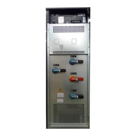
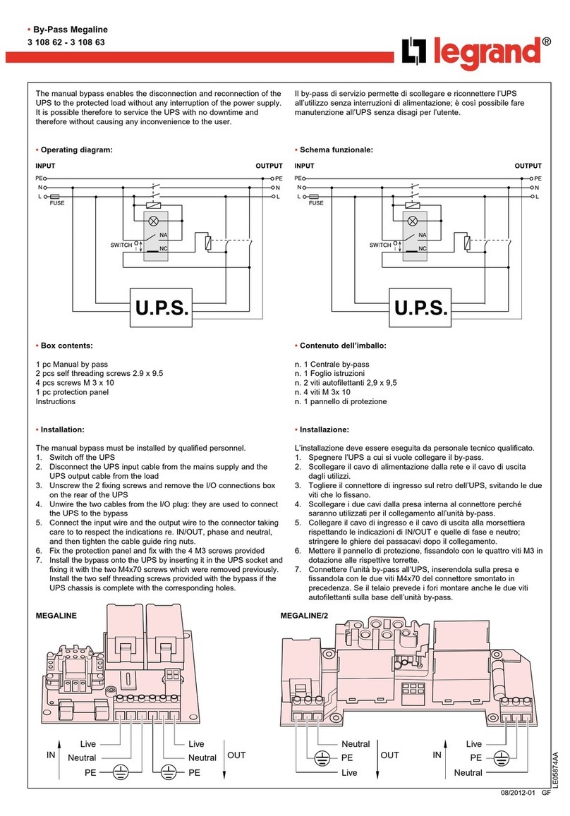
Elen C1 Series User manual

C1 SERIES USER MANUAL
C1 Series 30-120kVA Rev 1.0.1 Page | 1
TABLE OF CONTENTS
1. Overview ................................................................................................................................4
2. Safety ......................................................................................................................................5
2.1. Warnings ...................................................................................... 5
2.2. Explanation of symbols used ........................................................ 5
3. Installation.............................................................................................................................6
3.1. Choosing the right location ......................................................................6
3.2. Device transportation ...............................................................................7
3.3. Unpacking and placing the UPS ...............................................................7
3.4. Providing electrical connections ................................................................9
3.4.1. Input feedback protection .................................................................9
3.4.2. Cross-sections of cables to use ........................................................9
3.4.3. Placing batteries ............................................................................ 10
3.4.4. Providing cable connections ........................................................... 14
3.4.4.1. Providing external battery cabin connections ........................ 17
4. Operation modes ..............................................................................................................19
4.1. Online (normal) operation mode ............................................................. 19
4.2. Battery operation mode .......................................................................... 19
4.3. Bypass operation mode .......................................................................... 20
4.4. System off mode ................................................................................... 20
5. Front panel and menu structure ..................................................................................22
5.1. Front panel structure ............................................................................. 22
5.2. Menu structure ...................................................................................... 25
5.2.1. Main menus ................................................................................... 26
5.2.1.1. Displays ............................................................................... 26
5.2.1.2. UPS status ........................................................................... 27
5.2.1.3. Warnings ............................................................................. 29
5.2.1.4. Custom settings ................................................................... 32
6. Operating procedures .....................................................................................................35
6.1. Switching the UPS on ............................................................................ 35
6.2. Starting the UPS .................................................................................... 36
6.3. Stopping the UPS .................................................................................. 37
6.4. Switching the UPS off ............................................................................ 37
6.5. Manual bypass operation ....................................................................... 38
6.5.1. Switching the UPS to manual bypass mode .................................... 38

C1 SERIES USER MANUAL
C1 Series 30-120kVA Rev 1.0.1 Page | 2
6.5.2. Switching the UPS back from manual bypass mode ........................ 40
6.6. Economic operation mode (ECO-MOD) .................................................. 40
6.6.1. Activating economic operation mode .............................................. 40
6.6.2. Deactivating economic operation mode .......................................... 41
6.7. Emergency stop procedure (EPO) .......................................................... 41
6.8. Operation during mains fail ..................................................................... 42
6.9. Remote start and stop of the UPS .......................................................... 43
6.10. Testing batteries .................................................................................... 43
6.11. Operation on generator .......................................................................... 45
6.12. Operation during an overload ................................................................. 45
7. Parallel operation ......................................................................................... 47
7.1. Installation ............................................................................................. 47
7.2. Settings ................................................................................................. 49
7.3. Starting the parallel system .................................................................... 51
7.4. Stopping the parallel system ................................................................... 52
7.4.1. Stopping any UPS in the system .................................................... 52
7.4.2. Stopping all UPSs in the system ..................................................... 53
8. Communication .................................................................................................................55
8.1. RS-232 and RS-485 communication options ........................................... 55
8.2. Mod-bus communication option .............................................................. 56
8.3. SNMP communication ........................................................................... 56
8.4. Remote monitoring panel ....................................................................... 57
8.5. Programmable relay unit ....................................................................... 58
8.6. Custom contacts .................................................................................... 60
9. Troubleshooting ................................................................................................................61
10. Maintenance .......................................................................................................................63
11. Technical specifications ................................................................................................64

C1 SERIES USER MANUAL
C1 Series 30-120kVA Rev 1.0.1 Page | 3
Introduction
Thank you for choosing our high technology C1 Series™ uninterruptible power
supply. Product you purchased was manufactured as per ISO9001 quality assurance
system using most advanced technology.
In order to get highest efficiency from your product and to ensure a safe use, we
recommend that you strictly read and retain this user’s manual for later reference. In
addition, do not hesitate to contact your nearest authorized vendor or technical
support center for more detailed information and/or assistance.

C1 SERIES USER MANUAL
C1 Series 30-120kVA Rev 1.0.1 Page | 4
1. Overview
C1 Series Uninterruptible Power Supply (UPS) is a high technology product
that was manufactured to provide uninterruptible energy to fields including but not
limited to industrial facilities, hospital, schools, banks, business centers, and
computer and communication systems. You can use your device, which is equipped
with static bypass system, all necessary protection systems and an online structure
with all loads safely.
Because this device was designed double conversion online system basis, it
supplies all connected loads with continuous voltage with stable frequency and stable
amplitude. Therefore, no transition period is necessary when electric power is
interrupted or recovered.
With deployment of a DSP (Digital Signal Processor) based microprocessor
in its design, UPS output voltage is accurately controlled, thereby ensuring stable
operation of devices that are sensitive to voltage fluctuations.
Static bypass unit of the system ensures that the mains voltage is constantly
kept at backup. In case of an overload, this system takes over the load
uninterruptedly. Once overload is recovered, load is transferred back to inverter. In
addition, static bypass unit acts in similar way in cases of UPS failure and prevents
power shortage at the system.
UPS will supply loads from the battery in cases of mains voltage outage.
Loads are supplied from the battery for a backup time that varies depending on the
capacity of batteries used. If mains voltage is recovered during the backup time, UPS
will return to online mode automatically and continue supplying power to loads.
Meanwhile, batteries are charged as well.
When UPS is connected to a computer system using any of a several
communication options, all functions of the device can be monitored by means of
designated software. Connecting to a remote device via modern is possible to
transfer information on device related functions and problems.
System used in C1 series uninterruptible power supply is shown in the
following simple block diagram.
Figure–1 UPS block structure

C1 SERIES USER MANUAL
C1 Series 30-120kVA Rev 1.0.1 Page | 5
2. Safety
This user manual contains all information pertaining to transportation,
installation and operation of C1 Series uninterruptible power supplies of 30-120 KVA
power range.
2.1 Warnings
Be sure to read this user manual thoroughly before operating you UPS
system.
Heed all warnings given in this user manual.
Please apply all instructions in respective order.
Device must be operated in vertical position in all cases.
Do not expose device to rain or liquid spillage.
Device must be installed and commissioned by an authorized service
personal.
Please do not remove device cover. There parts in device that not
serviceable by the user. Contact a technical service unit in case of any
failure.
Do not operate the UPS in environments with temperature and/or humidity
that exceed the temperature and humidity limits set forth in technical
specifications section.
Contact with batteries of the UPS is highly dangerous. Even all the switches
are thrown off; there will be high voltage on battery contacts.
Do not open the plastic cover of the batteries. Electrolyte liquid inside
batteries is highly hazardous to skin and eyes.
If connection of external batteries necessary, make sure only the batteries
that are compatible with device are connected and that connection is made
by authorized personnel only.
Explosion Hazard: Do not litter batteries in fire.
2.2 Explanation of symbols used
DANGER! HIGH VOLTAGE
CAUTION

C1 SERIES USER MANUAL
C1 Series 30-120kVA Rev 1.0.1 Page | 6
3. Installation
3.1 Choosing the right location
Uninterruptible power supplies are devices that consist of highly
delicate circuits. Therefore, the environment to install and run UPS
must be carefully analyzed and chosen.
Uninterruptible power supply operates at temperatures between 0–40 C.
However, environment temperature must be maintained in the range of 20–
25 C so that the inner heat of the UPS can be adequately cooled down.
Cooling devices that provide ample ventilation to keep environment
temperature within the range given above must be utilized in installation
environment. Power of the air conditioner required in installation
environment is given below.
UPS Power (KVA) 30
40
60
80
100
120
Air Conditioner Power
(BTUx1000) 9 11
15
19
24 30
Table–1 Air conditioner power for different UPS power
UPS must be positioned so that the
ventilation inlets/outlets shown on the
figure are not blocked.
Figure–2 UPS’ ventilation inlets
and outlets
Distance that must be observed
around the UPS should be as
indicated in the figure-3.
Figure–3 Distance to be observed
around the UPS

C1 SERIES USER MANUAL
C1 Series 30-120kVA Rev 1.0.1 Page | 7
Place the UPS so that it will not be exposed to direct sunlight or radiated
heat.
Environment to operate the UPS should be carefully chosen to ensure that it
will not be any influence by dust, iron filings, oil, and miscellaneous
manufacturing wastes.
Operating environment should be free of flammable and caustic gasses
such as hydrogen sulfur, sulfuric acid, chloride, ammonia, nitric acid, ozone,
and hydrochloric acid and alike,.
Surface to set the UPS must be even and of a sound structure that
can carry the device and –preferably, plastic coated.
3.2 Device transportation
Carry the UPS to installation location along with the palette it was shipped
on using a forklift or pallet jack.
Figure–4 Transporting the UPS
Strictly, do not carry the UPS in horizontal position. UPS must be
carried in upright (vertical) position only.
3.3 Unpacking and placing the UPS
If UPS shall be kept at the depot for a prolonged period of time, do not
remove packaging until the installation.

C1 SERIES USER MANUAL
C1 Series 30-120kVA Rev 1.0.1 Page | 8
Cut the black protection band shown in
figure and remove the nylon protective
material inside the card box.
Figure–5 Removing packaging
Lift the card box upwards to remove.
Remove Styrofoam protective materials fit on upper corners of the UPS.
Once unpacked, examine the UPS carefully. UPS may have been
damaged during the transportation.
Check to ensure that all standard (user manual, communication cable,
parallel cable and warranty certificate) and optional products ordered were
shipped with the device without omissions.
UPS is mounted on the palette from front and back sides using fixation
elements.
Figure–6 Unloading UPS from the palette
Remove front and back fixation elements shown in Figure-6 (A).
Unload the UPS carefully from the palette.
Roll the UPS on rollers shown in Figure-6 (B) to the place where UPS will be
operated.

C1 SERIES USER MANUAL
C1 Series 30-120kVA Rev 1.0.1 Page | 9
3.4 Providing electrical connections
3.4.1 Input feedback protection
This UPS includes no internal circuit for protection against feedback
currents. Therefore, it is essential that users or those who installed the UPS put
warning labels on all circuit interrupt switches deployed on the line where
uninterruptible power supply is used. Warning labels should remind that a UPS
device is operating on this line to technical personnel to service these circuits.
Warning labels should be as follows.
3.4.2 Cross-sections of cables to use
Cross-sections of cables to be used are given in the following table. Be
sure to adhere to following cable cross-section specifications for a safe
operation.
UPS
Power
(KVA)
Input
(mm2)
Output
(mm2)
Ground
(mm2)
Battery
Cabinet
(mm2)
Battery
Cabinet
Ground
(mm2)
30 4 x 10 4 x 10 1 x 10 3 x 6 1 x 10
40 4 x 16 4 x 16 1 x 16 3 x 10 1 x 16
60 4 x 25 4 x 25 1 x 25 3 x 16 1 x 25
80 4 x 35 4 x 35 1 x 35 3 x 25 1 x 35
100 4 x 50 4 x 50 1 x 50 3 x 35 1 x 50
120
4 x 70 4 x 70 1 x 70 3 x 50 1 x 70
Table–2 Cable cross-sections
Battery cable cross-sections given in the table above is for cables to be
connected between external battery cabin and UPS.
BE SURE TO ISOLATE THE UPS PRIOR TO
SERVICING THIS CIRCUIT

C1 SERIES USER MANUAL
C1 Series 30-120kVA Rev 1.0.1 Page | 10
3.4.3 Placing batteries
Six rail-type battery trays are available in 30-40KVA. Batteries can be placed
inside these trays. Types and quantities of batteries that may be placed inside these
trays are given in the following table.
Battery
Type
(Ah)
Battery
Quantity
(Pieces)
Battery Cable
Cross-section
(mm2)
Remarks
4.5 64 / 128 / 192
2.5 Use 32 batteries in each tray.
7 64 / 128 2.5 Use 22 and 20 batteries in
each tray in order.
9 64 / 128 2.5 Use 22 and 20 batteries in
each tray in order.
12 64 4 Use 16 batteries in each tray.
Table–3 Batteries that can be used in battery tray
Cable cross-sections given in the table above are for connection cables for
patching between batteries in the tray.
If type or quantity of your batteries is different than specifications given
in table above, you will have to use an external battery cabin. Please
contact technical service for details on type and quantity of batteries to
be used in an external battery cabin.
Follow the following steps while placing batteries in trays inside the UPS.
Make sure that all switches are closed (off) before proceeding with the
following steps.
Remove respectively upper and left-side covers of the UPS.
Begin placing batteries from the lowest tray.
Heed all warnings while working with batteries. Batteries pose
substantial electric shock hazard.
Remove wristwatch, rings, and all other metal accessories.
Be sure to use tools with isolated handles only. Do not leave tools or other
metal objects on batteries.
Wear isolating gloves and boots.

C1 SERIES USER MANUAL
C1 Series 30-120kVA Rev 1.0.1 Page | 11
Remove fixation elements shown in Figure-7
(C) that anchor battery tray to device chassis.
Figure–7 Battery tray fixation parts
Figure–8 Upper and lateral fixation parts in the tray
Remove fixation elements in the tray, shown in Figure-8
(E) and (F).
Place batteries on tray.
You can make use of following figures when placing batteries or making
battery connections inside the tray.

C1 SERIES USER MANUAL
C1 Series 30-120kVA Rev 1.0.1 Page | 12
Once you placed batteries inside the battery tray, follow these steps:
Reinstall battery’s lateral fixation part.
Attach connection cables of batteries inside the tray.
Push the tray back in place and fix it to device chassis using the fixation
part.
Repeat steps above in respective order for every other tray.
For 64 batteries of 4.5Ah, 1st and 2nd trays are used.
For 128 batteries of 4.5Ah, 1st, 2nd, 3rd and 4th trays are used.
For 192 batteries of 4.5Ah, 1st, 2nd, 3rd, 4th, 5th and 6th trays are used.
Figure
–
9 Battery trays
placement
Figure
–
10 Configuration of 4.5Ah
batteries
1
2
3
4
5
6

C1 SERIES USER MANUAL
C1 Series 30-120kVA Rev 1.0.1 Page | 13
Do not connect the socket fixed on device
chassis, shown in Figure-11 (D) and the socket
fixed to battery tray. This should be done
once all connections are provided.
Figure–11 Connection sockets between trays
Figure-12 Configuration of 7-9 Ah batteries
For 64 batteries of 7-9Ah, 1st, 2nd and 3rd trays are used.
For 128 batteries of 7-9Ah, 1st, 2nd, 3rd, 4th, 5th and 6th trays are used.
1
2
3
4
5
6

C1 SERIES USER MANUAL
C1 Series 30-120kVA Rev 1.0.1 Page | 14
Figure-13 Configuration of 12 Ah batteries
For 64 batteries of 12Ah, 1st, 2nd, 3rd and 4th trays are used.
3.4.4 Providing cable connections
UPS’s backside appearance of 30-40KVA, 60-80KVA and 100-120KVA is as shown
following.
Make sure that all switches located on power switches unit, shown on
the figure on the right, are thrown off.
Remove connection terminal protection cover shown in the figure on the
right.

C1 SERIES USER MANUAL
C1 Series 30-120kVA Rev 1.0.1 Page | 15
(a) 30-40KVA
Figure–14 Rear view of 30-40KVA
Detail terminal layout of 30-40KVA is shown in the following drawing.
L1
L2
L3
N1
L1
L2
L3
N2
+
0
-
L1
L2
L3
N3
Ξ
INPUT
EXTERNAL BYPASS
BATTERY
OUTPUT
E
Figure–15 Connection terminals layout of 30-40KVA

C1 SERIES USER MANUAL
C1 Series 30-120kVA Rev 1.0.1 Page | 16
(a) 60-80KVA (b) 100-120KVA
Figure–16 Rear view of 60-120KVA
Detail terminal layout of 60-120KVA is shown in the following drawing.
L1
L2
L3
N2
+
0
-
Ξ
EXTERNAL BYPASS
BATTERY
E
L1
L2
L3
N1
L1
L2
L3
N3
INPUT
OUTPUT
Figure–17 Connection terminals layout of 60-120KVA
Make sure to connect earth connection before proceeding with all other
connections of the UPS.
Connect earth cable to terminal labeled “E” (Earth).
Connect input cables to terminals labeled “INPUT” (L1, L2, L3, N1)
sequentially.

C1 SERIES USER MANUAL
C1 Series 30-120kVA Rev 1.0.1 Page | 17
Observe phase sequence while connection input cables. In case of any
mistakes in phase sequence, UPS will give ‘Phase Sequence Fault’
warning.
If there is an external supply, connect its cables to terminals labeled
“EXTERNAL BYPASS” (L1, L2, L3, N2) sequentially.
Connect output cables to terminals labeled “OUTPUT” (L1, L2, L3, N3)
sequentially.
3.4.4.1 Providing external battery cabin connections
When a backup time that is longer than backup time normally provided by
the internal battery group is necessary, batteries designated by the manufacturer
may be connected externally. In that case, follow the steps below to connect batteries
located inside external tray(s) to device.
If the distance between battery cabins and the UPS is longer than three (3)
meters, wrap battery cables together.
Battery terminals of UPS with external battery groups have dangerous
voltage. Be sure to remove internal battery group from the (red-black)
sockets fixed to battery trays of the UPS before proceeding with making
external battery connections (Figure–11).
Be sure to adhere to polarity while connecting battery cables as shown
in the following drawing. Polarity faults will damage the UPS.
Figure–18 Battery cabin connection (for single battery cabin)

C1 SERIES USER MANUAL
C1 Series 30-120kVA Rev 1.0.1 Page | 18
Figure–19 Battery cabin connection (for two battery cabins)
If batteries are located in two separate cabins, make sure that
quantities and capacities of batteries on both cabins are identical. Equal
quantity of batteries should be used for plus (+) and minus (-) busbars
in external battery cabins.
Do not make any connection to battery terminals of UPSs that do not
have external cabin. Once all electrical connections were completed,
connect the sockets of internal battery trays to sockets fixed to device
chassis.

C1 SERIES USER MANUAL
C1 Series 30-120kVA Rev 1.0.1 Page | 19
4. Operation modes
4.1 Online (normal) operation mode
C1 Series UPS devices supply all connected loads with continuous voltage
with stable frequency and stable amplitude during online operation.
Rectifier and inverter units run continuously. Load is supplied with a stable
sinusoidal voltage generated by the inverter. Inverter and bypass voltages are
synchronized. Batteries are constantly kept at a buffer charge voltage. Mimic diagram
displayed on the LCD screen is as shown below. During this operation mode, LED
bar is constantly lit in green.
Figure–20 Online (normal) operation mode
UPS will switch back from this operation mode when any of the following occurs:
Mains voltage or mains frequency is out of limits
Overheat or overload
Battery test procedure
A failure
4.2 Battery operation mode
Rectifier unit does not run, inverter unit runs. Inverter unit is supplied from
the battery. Load is supplied a stable sinusoidal voltage generated by the inverter.
Batteries are in discharge position. Mimic diagram is as shown in the following
drawing. In this operation mode, LED bar flashes green.
Figure–21 Battery operation mode

C1 SERIES USER MANUAL
C1 Series 30-120kVA Rev 1.0.1 Page | 20
When any of the following occurs, UPS will switch to this operation mode.
Mains voltage or mains frequency is out of limits
Mains phase sequence fault
Battery test procedure
4.3 Bypass operation mode
Inverter and rectifier units do not run. Load is supplied by bypass source
over static bypass unit. Mimic diagram is as shown in the following drawing. In this
operation mode, LED bar is constantly lit in red.
Figure–22 Bypass operation mode
When any of the following occurs, UPS will switch to this operation mode.
As soon as UPS is turned on
Cases of overheat shutdown, overload shutdown or overcurrent inverter
Stopping the UPS by remote bypass switch
Any failures in rectifier or inverter stages
4.4 System off mode
Rectifier, inverter and static bypass units do not run. In this operation mode,
LED bar will be fully off.
Figure–23 System off mode
Table of contents
Other Elen UPS manuals
