ATSG Chrysler 45RFE User manual

INDEX
Copyright © ATSG 1999 September, 1999
CHRYSLER 45RFE
2
AUTOMATIC TRANSMISSION SERVICE GROUP
9200 S. DADELAND BLVD. SUITE 720
MIAMI, FLORIDA 33156
(305) 670-4161
CLUTCH APPLICATIONCHART...................................................................................................................... 4
SOLENOID ON/OFFCHART............................................................................................................................... 5
CASECONNECTORANDTCM PIN CAVITYIDENTIFICATION............................................................... 11
WIRING SCHEMATIC ......................................................................................................................................... 13
CONTROLRELAYANDFUSE LOCATIONS .................................................................................................. 14
TRS/SOLENOIDBODYTESTS.......................................................................................................................... 18
OBDIIDIAGNOSTICTROUBLECODE IDENTIFICATION ........................................................................ 20
OILPASSAGEIDENTIFICATION..................................................................................................................... 22
LINEPRESSURETESTING................................................................................................................................ 30
GENERALOPERATIONINFORMATION........................................................................................................ 31
TRANSMISSIONDISASSEMBLYPROCEDURE............................................................................................. 32
COMPONENTREBUILDPROCESS
TRANSMISSION CASEASSEMBLY.............................................................................................................. 42
LOW/REVERSECLUTCHHOUSINGASSEMBLY..................................................................................... 44
2-4CLUTCHRETAINERASSEMBLY........................................................................................................... 50
GEAR TRAINCOMPONENTS........................................................................................................................ 53
INPUT CLUTCHHOUSINGASSEMBLY...................................................................................................... 54
INPUT CLUTCHHOUSINGSNAPRINGIDENTIFICATION................................................................... 56
OILPUMPASSEMBLYINCLUDING VALVES........................................................................................... 65
VALVEBODY ASSEMBLY .............................................................................................................................. 73
TRANSMISSIONFINALASSEMBLY................................................................................................................ 83
CHECKINGFRONTANDREAR END-PLAY ................................................................................................... 89
AIRPRESSURETESTS......................................................................................................................................... 91
END-PLAYSPECIFICATIONS............................................................................................................................ 96
FLUIDSPECIFICATIONS.................................................................................................................................... 96
TORQUESPECIFICATIONSANDBOLTIDENTIFICATION....................................................................... 97
EXPLODEDILLUSTRATIONSOFINTERNAL PARTS.................................................................................. 98
THRUSTBEARINGCHART............................................................................................................................... 108
SPECIALTOOLS.................................................................................................................................................. 109
IDENTIFICATIONTAG LOCATION................................................................................................................. 112
CAUTION: ATSG service manuals are intended for use by professional,
qualified technicians. Attempting repairs or service without the proper
training, tools and equipment could cause injury to you or others and damage
tothevehiclethat may causeitnottooperateproperly.
GO TO PAGE
PREVIOUS
MENU
AKPPHELP.RU Руководство по ремонту АКПП

INTRODUCTION
AUTOMATIC TRANSMISSION SERVICE GROUP
9200 S. DADELAND BLVD. SUITE 720
MIAMI, FLORIDA 33156
(305) 670-4161
DALE ENGLAND
FIELD SERVICE CONSULTANT
ED KRUSE
TECHNICAL CONSULTANT
WAYNE COLONNA
TECHNICAL SUPERVISOR
ROBERT D. CHERRNAY
TECHNICAL DIRECTOR
PETER LUBAN
TECHNICAL CONSULTANT
JIM DIAL
TECHNICAL CONSULTANT
GREGORY LIPNICK
TECHNICAL CONSULTANT
JERRY GOTT
TECHNICAL CONSULTANT
ARSENIO RIVERA
TECHNICAL CONSULTANT
DAVID CHALKER
TECHNICAL CONSULTANT
GERALD CAMPBELL
TECHNICAL CONSULTANT
CHRYSLER 45RFE
1
No part of any ATSG publication may be reproduced, stored in any retrieval system or transmitted in any form
or by any means, including but not limited to electronic, mechanical, photocopying, recording or otherwise,
without written permission of Automatic Transmission Service Group. This includes all text illustrations,
tablesand charts.
The information and part numbers contained in this booklet have
been carefully compiled from industry sources known for their
reliability, but ATSG does not guarantee its accuracy.
Copyright © ATSG 1999
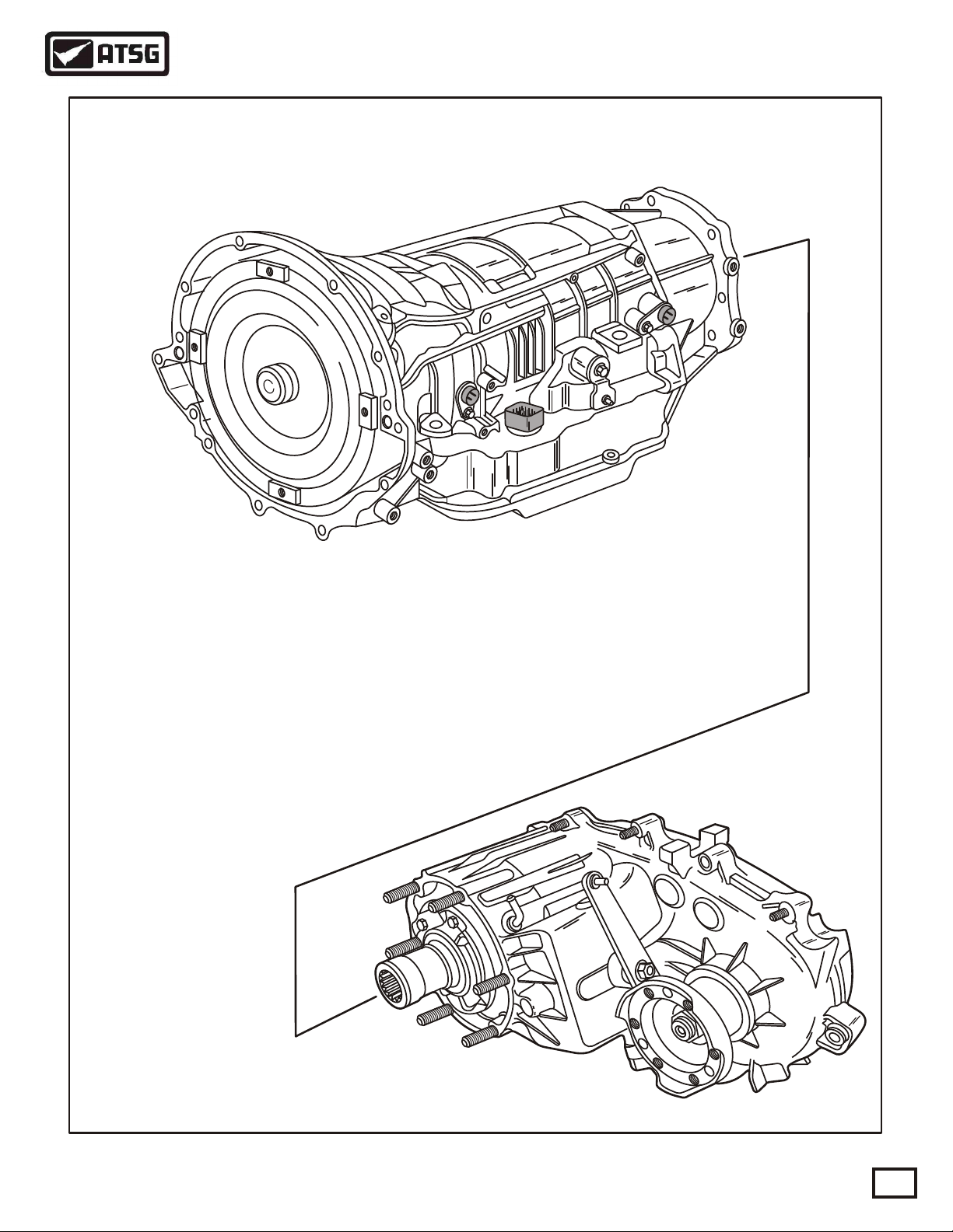
Beginning at the start of production for the 1999 model year Chrysler Corporation has introduced a brand new
rear wheel drive transmission for the 99 Jeep Grand Cherokee with the 4.7L engine, and scheduled for the Ram
Pick-up for the 2000 model year. This is the first completely new rear wheel drive automatic transmission from
Chrysler in more than thirty years. The 45RFE designation tells us that this new unit has 4forward speeds, a
relativetorque ratingof 5,isforReardrivevehiclesandisFullyElectroniccontrolled.RefertoFigure1.
AKPPHELP.RU Руководство по ремонту АКПП
AUTOMATIC TRANSMISSION SERVICE GROUP
Technical Service Information
3
JEEP GRAND CHEROKEE 45RFE TRANSMISSION
FOUND BEHIND 4.7L ENGINE FOR 1999
Copyright © 1999 ATSG
Figure 1
4= Four Forward Speeds
5= Relative Torque Capacity
R= Rear Wheel Drive
FE = Fully Electronic
AKPPHELP.RU Руководство по ремонту АКПП
AUTOMATIC TRANSMISSION SERVICE GROUP
Technical Service Information
4
Copyright © 1999 ATSG
CLUTCH APPLICATION CHART
SELECTOR
POSITION LO/REV
CLUTCH UD
CLUTCH SECOND
CLUTCH OD
CLUTCH GEAR
RATIO
LOW OVERRUN
CLUTCH
FOURTH
CLUTCH REVERSE
CLUTCH
PARK ON
ON ON 3.00:1
3.00:1
3.00:1
3.00:1
1.67:1
1.67:1
1.67:1
1.50:1
1.00:1
1.00:1
0.75:1
ON
ON
ON
ON
ON
ON
ON
ON
ON ON
ON ON
ON
ON
ON
ON
ON
ON
HOLD
HOLD
HOLD
REVERSE
NEUTRAL
OD-1ST
(1)-1ST
(2)-1ST
(2)-2ND
OD-2ND
OD-3RD
OD-4TH
OD-LIMP
(2)-LIMP
2ND PRIME
ON*
ON*
ON*
L/R Clutch is on only with the output shaft speed below 150 RPM.
*
Figure 2
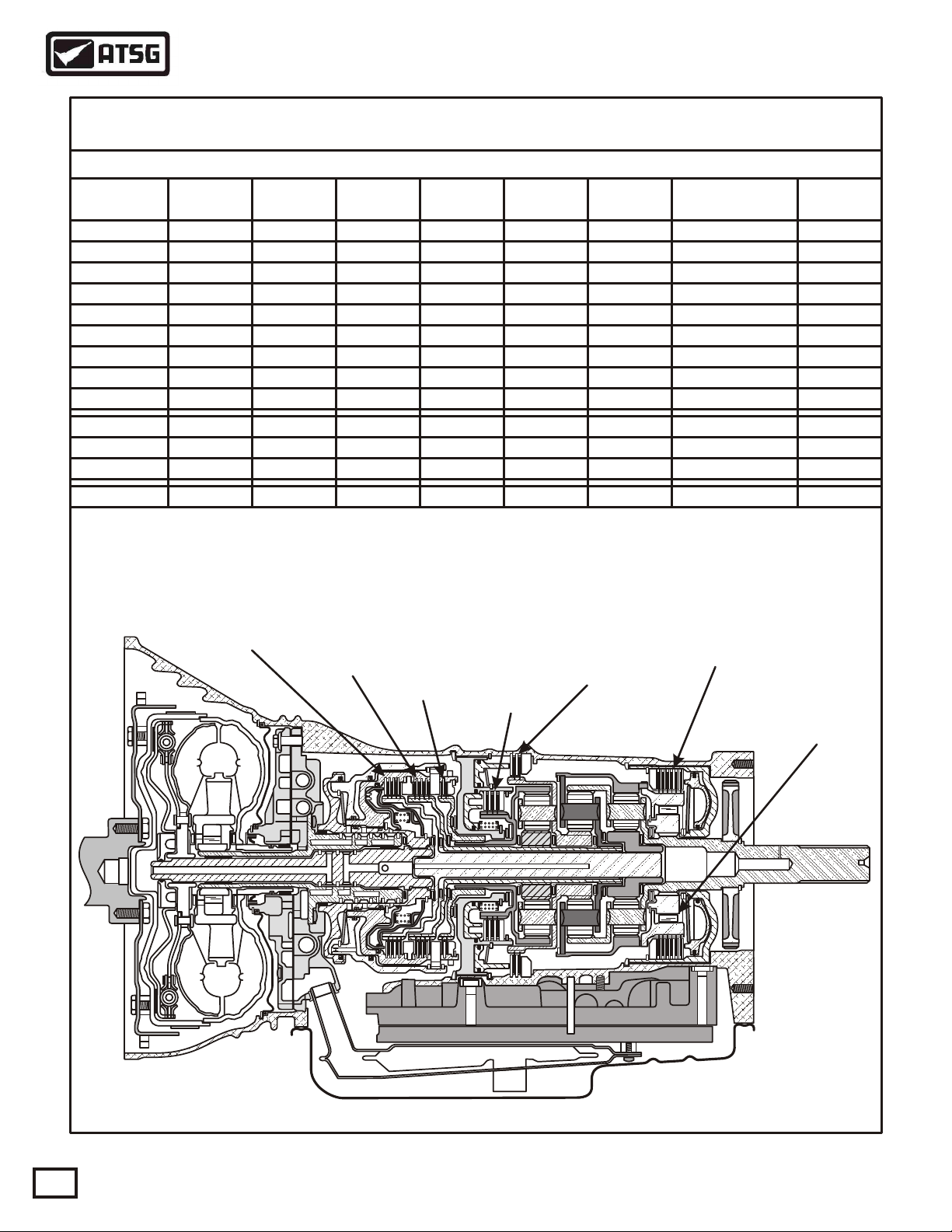
Underdrive
Clutch Overdrive
Clutch Reverse
Clutch
Second
Clutch
Fourth
Clutch
Low/Reverse
Clutch
Low Roller
Clutch
AKPPHELP.RU Руководство по ремонту АКПП

AUTOMATIC TRANSMISSION SERVICE GROUP
Technical Service Information
5
Copyright © 1999 ATSG
The operation of the 45RFE is very similar to the Chrysler 41TE (A604) and 42LE (A606) transaxles that you
are already familar with. The 45RFE has no internal bands, but uses several different clutch assemblies instead.
The Input Clutch Housing retains the underdrive clutch, overdrive clutch and the reverse clutch and is set up
almost identical to the 41TE transaxle, except much larger. The 45RFE also contains seperate holding clutches,
such as the 2nd clutch, 4th clutch and the low/reverse clutch. This unit also uses one overrunning or freewheel
devicecalled thelow overrunclutch.
To achieve its different gear ratios, the 45RFE applies different combinations of two clutch packs at a time, as
shown in Figure 2. In Park and Neutral, only the low/reverse clutch is applied. Notice also that a unique
characteristic of the 45RFE is its alternate 2nd gear ratio, or "2nd prime" as it is known. The 2nd prime is
enabled only during kickdown shifts above certain speeds, that enhances vehicle performance by allowing for a
higher gear ratio passing gear at highway speeds. Refer to the chart in Figure 2 for the clutches that are applied
foreach shiftlever position.
Another feature ofthisunit is thethreeplanetary gearsets,asshown inFigure2, which isonemore than youare
used to seeing in a Chrysler unit. These planetary gear sets provide a deeper 1st and reverse ratio and does not
needa seperateoverdrive unit. AllgearratiosarealsoshowninthechartinFigure2.
MECHANICAL OPERATION
Modulating (EMCC) if the Converter Clutch has been signaled.
*
SOLENOID CHART
SELECTOR
POSITION LR/CC
SOLENOID UD
SOLENOID OD
SOLENOID 2nd CLUT
SOLENOID 4th CLUT
SOLENOID Multi-Select
SOLENOID Variable Force
SOLENOID
P/N
Under 8
P/N
Over 8
(1)-1ST Or
Autostick
ON
N.O. N.O. N.O. N.O.N.C. N.C.
ON
ON
OFF OFF OFF OFF OFF OFF OFF
OFF
ON
ON
ON
ON
ON
ON
ON
ON
ON
ON ON
ON
ON
Modulating
Modulating
Modulating
Modulating
Modulating
Modulating
Modulating
Modulating
Modulating
Modulating
REVERSE
FAILSAFE
REV-Block
OD-1ST
OD-2ND
OD-3RD
OD-4TH
2ND PRIME
*
*
*
*
Figure 3
AKPPHELP.RU Руководство по ремонту АКПП

AUTOMATIC TRANSMISSION SERVICE GROUP
Technical Service Information
6
Copyright © 1999 ATSG
ELECTRICAL OPERATION
TheTransmissionControlModule(TCM)controlsallofthetransmissionfunctionsandis locatedin theengine
compartment, as shown in Figure 5. The Powertrain Control Module (PCM)does not control the transmission.
The electronic components of the 45RFE transmission consist of various sensors and switches as input
information to the TCM, that the TCM uses to determine the appropriate gear ratio and shift schedule points.
There is also the associated wiring, fuses, relays, connectors, splices and grounds for the transmission to
functionas designed. Acomplete transmissionwiringschematichasbeenprovidedforyouinFigure9.
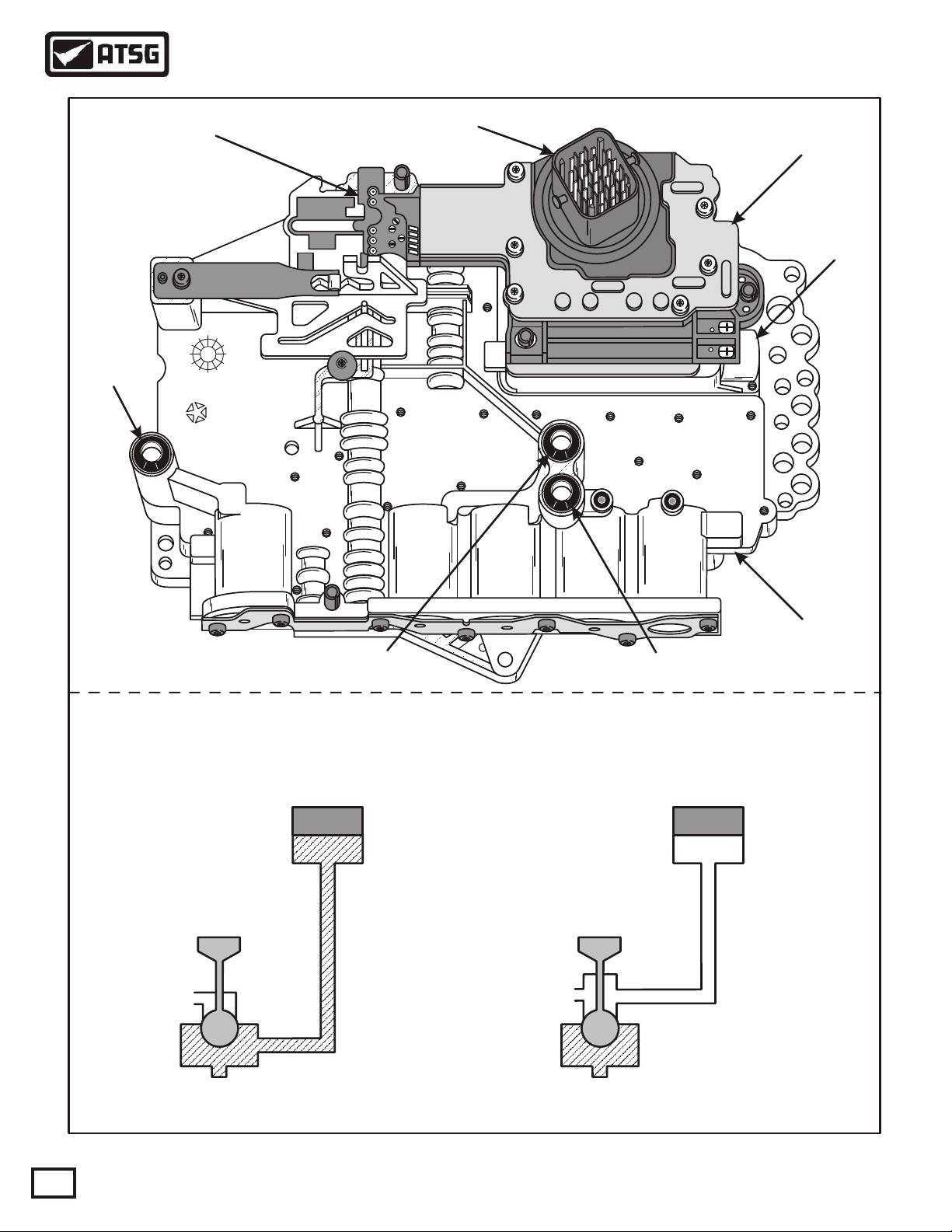
The final output from the TCM is to the six shift solenoids and the line pressure control solenoid located in the
Solenoid Pack/Transmission Range Sensor assembly and bolted on the valve body as shown in Figure 4. The
solenoids in this transmission are unique in that some are normally vented and some are normally applied and is
illustrated in Figure 4. The TCM also communicates with other control modules, such as the PCM, currently
using the two wire CCD Bus for communication. The TCM recieves power from two sources, fused battery
power to pin 56 and fused ignition switch input to pin 11, both at the 60-way connector on the TCM. The TCM
alsohas aground tocompleteitselectricalcircuit.(SeeFigure8).
INPUTS TO THE TCM
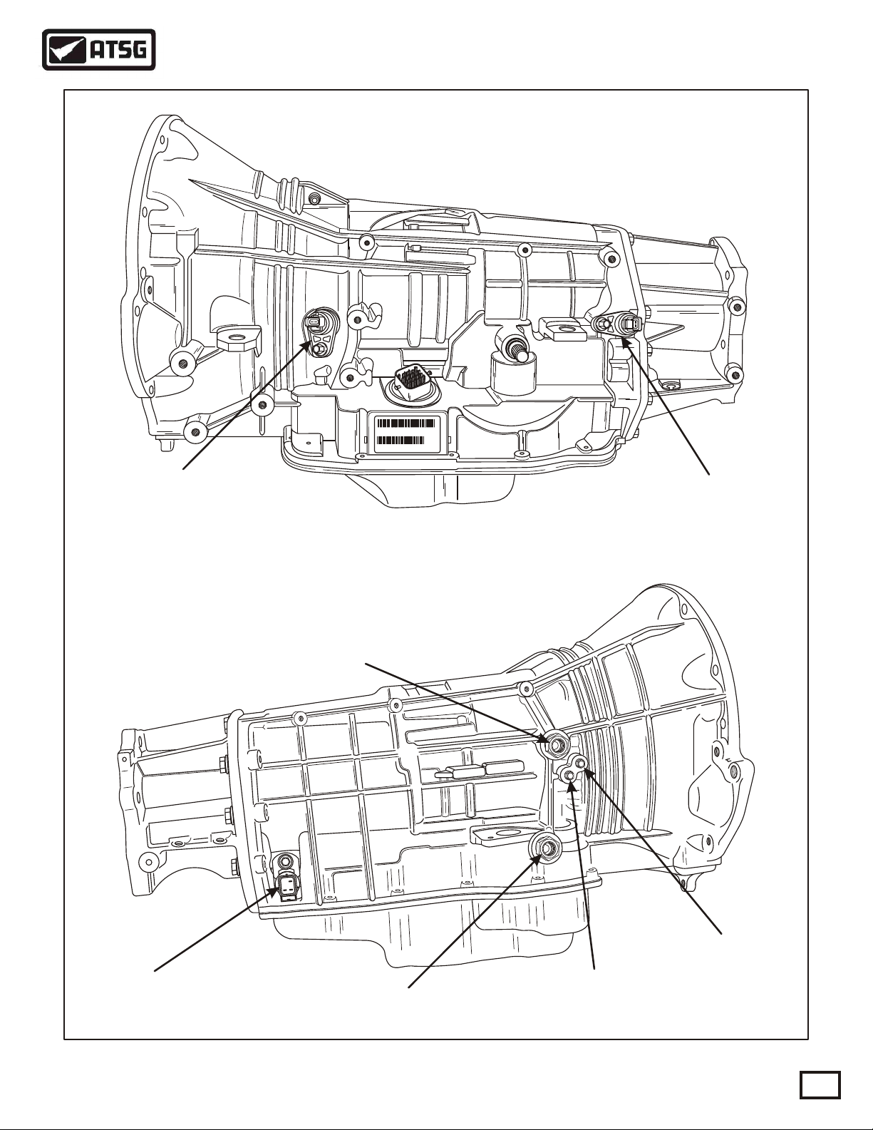
Input and Output Shaft Speed Sensors - are located on the left side of the transmission and are illustrated in
Figure 11. The input shaft speed sensor reads input shaft speed off of a tone wheel. The TCM compares this
reading with that of the output shaft speed sensor, which is also read off of a tone wheel. This comparison
provides the TCM with gear ratio information. The crankshaft position sensor supplies the TCM with engine
RPMdata thatis alsocritical toschedulingshiftpoints.
Line Pressure Sensor - is located on the right rear of the transmission, as illustrated in Figure 11, and supplies
theTCM withline pressureinformation. Thelinepressuresensoroperatesmuchlikeathrottlepositionsensor.
Transmission Fluid Temperature Sensor - is located in the Solenoid Pack/Transmission Range Sensor and is a
thermisterthat theTCMusestomonitertransmissionfluidtemperature.
OverdriveCancel Switch- locatedon theshift leverand cancelsoverdriveoperation.
Solenoid Pack/Transmission Range Sensor- contains several different inputs to the TCM. The TRS contains
five switches that tell the TCM, through different combinations of switch states, what position the manual gear
selectorhas beenplaced. There isalsoaback-uplampswitchincorporatedintheTRS.
In addition to the switches above, there are five pressure switches to moniter pressure in the Low/Rev, Second
Clutch, Fourth Clutch, Underdrive Clutch and Overdrive Clutch hydraulic circuits. The primary function of
these switches is to help the TCM detect when clutch circuit hydraulic failures occur. The TCM continuously
monitorsthe switchesfor thecorrectstates(OpenorClosed)ineachgearasshowninthechartinFigure5.
AKPPHELP.RU Руководство по ремонту АКПП

AUTOMATIC TRANSMISSION SERVICE GROUP
Technical Service Information
7
Copyright © 1999 ATSG
OUTPUTS FROM THE TCM
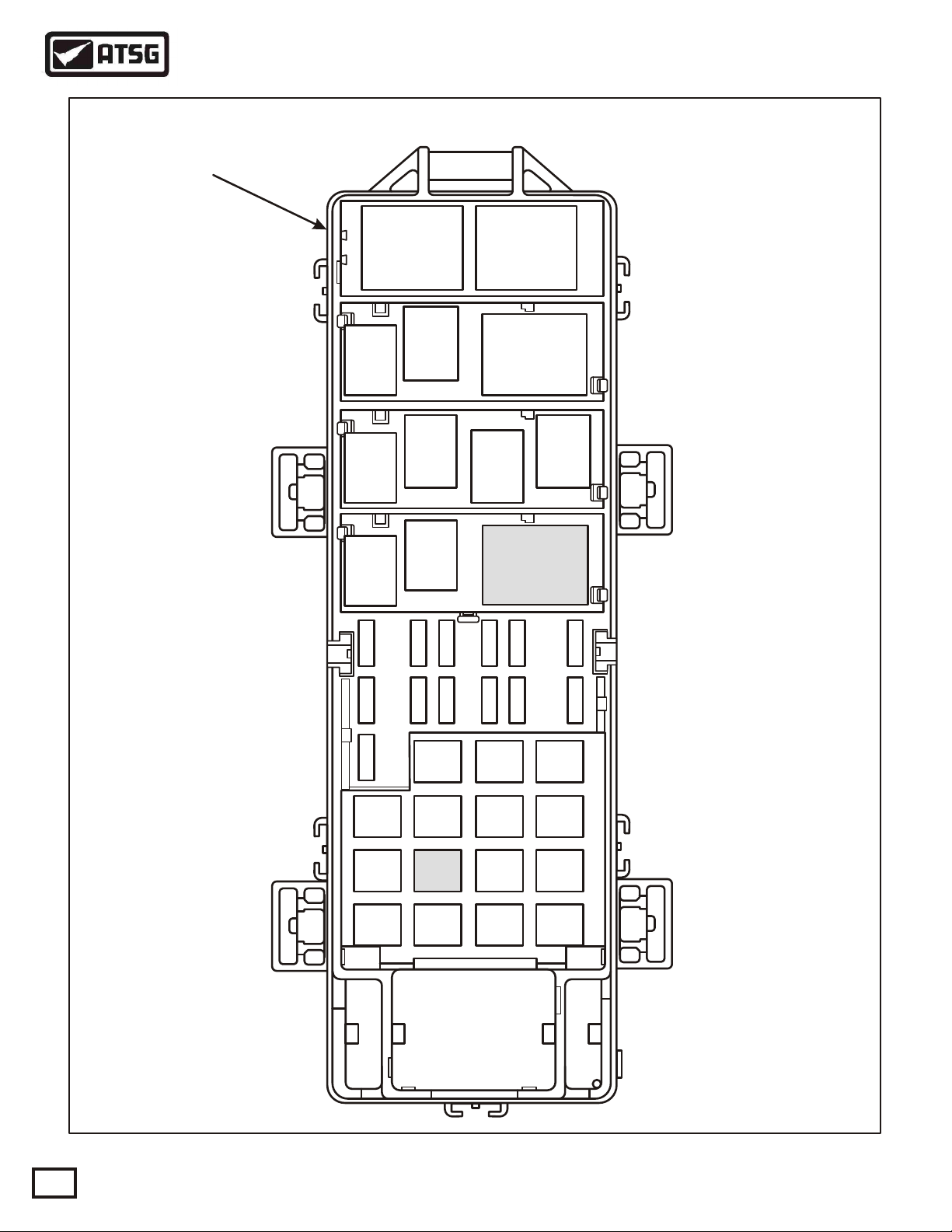
Transmission Control Relay - located in the Power Distribution Center (PDC), as shown in Figure 10, and
recieves a ground signal from terminal 15 at the TCM to close the relay. Refer to the wiring schematic in Figure
9.
UnderdriveSolenoid withPressureSwitch- Thissolenoid isnormally appliedand controlsoil tothe UDclutch
inall 1st,2nd,2ndPrimeand3rdgearsofthetransmission.
OverdriveSolenoidwithPressureSwitch-Thissolenoidisnormallyventedandcontrolsoilto theOD clutchin
3rdand 4thgears inthetransmission.
Fourth Clutch Solenoid with Pressure Switch - This solenoid is normally vented and controls oil to the 4th
clutchin all4th and2ndPrimegearsinthetransmission.
Second Clutch Solenoid with Pressure Switch - This solenoid is normally vented and controls oil to the 2nd
clutchin all2nd gearsinthetransmission.
Low/Reverse Solenoid with Pressure Switch - This solenoid is normally vented and is used to apply the L/R
clutchin 1stfromneutral,orcoastdownto1st,andtocontroloilforconverterclutchengagement.
Multi-Select Solenoid - The Multi-Select Solenoid is normally applied and controls the OD clutch in 3rd gear
Limp-in,2nd clutchinManual2,2ndLimp-inandtheLow/Reverseclutchinreverse.
LIMP-IN MODE OPERATION
DIAGNOSIS AND SERVICE INFORMATION
The TCM has the ability to monitor all transmission related electrical components and if it detects a problem,
takes appropriate action, and most of the time results in the TCM setting a Diagnostic Trouble Code (DTC).
Whetherthis resultsinMILillumination,orLimp-inModeoperation,dependsonthetypeofDTCthatwasset.
IftheTCMdeterminesthat transmission damage may resultfromtheDTC type that was set,theTCMwillshut
off the ground signal to the transmission control relay which will shut off all power to the transmission and the
vehiclewill bein Limp-inModeOperation.
When in Limp-in Mode Operation, with the shift lever in the "Drive" position the transmission will be in 3rd
gear,andif theshift leverismoved to"2"or "L"positionthetransmissionwill bein2nd gear. Thiswillallow the
driverto manuallyshiftthetransmissiontoLimphome.
You have been provided with the 23-way case connector pin cavity identification and pin function in Figure 7,
and 60-way TCM connector pin cavity identification and pin function in Figure 8. A complete transmission
wiringschematicisprovidedinFigure9, andtransmission controlrelaylocationinthepowerdistribution center
isshown inFigure 10.
Special tools that might be needed are illustrated in Figure 12, along with the identification of the pressure taps
that are available on the main valve body. Air pressure test passage identification is provided for you in Figure
13.
ADAPTIVE LEARNING
The 45RFE transmission uses an "Adaptive Learning" feature which allows the TCM to modify the clutch
applyratetomaintainconsistantshiftquality. Thisisdone basedon theamountofwearonthefriction elements.
The TCM then adjusts the duty cycle of the shift solenoids to achieve the smoothest possible upshifts and
downshifts. The TCM adjusts the "Clutch Volume Index" when a shift change takes place to optimize clutch to
clutch timing. Clutch Volume Index is described in Figure 6, along with proper clutch volumes and clutch
clearancesfor the45RFE transmission.
AKPPHELP.RU Руководство по ремонту АКПП
AUTOMATIC TRANSMISSION SERVICE GROUP
Technical Service Information
8
Copyright © 1999 ATSG
Figure 4
"Solenoid Off"
"Normally Applied" "Solenoid Off"
"Normally Vented"
Underdrive Solenoid
Multi-Select Solenoid
Overdrive Solenoid
4th Clutch Solenoid
2nd Clutch Solenoid
Low/Reverse Solenoid
TWO DIFFERENT TYPES OF SHIFT SOLENOIDS
4799591
97
VALVE BODY
PRESSURE
CONTROL
SOLENOID
SOLENOID
PACK
23-WAY
CONNECTOR
TRANSMISSION
RANGE SENSOR
4th Clutch
Seal
2nd Clutch
Seal
L/R Clutch
Seal
AKPPHELP.RU Руководство по ремонту АКПП

AUTOMATIC TRANSMISSION SERVICE GROUP
Technical Service Information
9
Copyright © 1999 ATSG
SWITCH CHART
2nd Clut 4th Clut Underdrive Overdrive
Reverse
First
Second
2nd Prime
Third
Fourth
Park/Neut
Low/Rev
Closed
Closed
Closed
Closed
Closed
Closed Closed
Closed
Closed
Closed
Closed*
Open Open
Open
Open
Open
Open
Open
Open
Open
Open
Open
Open
Open
Open
Open
Open
Open
Open
Open
Open
Open
Open
Open
Open
* L/R is closed if output speed is below 150 RPM in Drive and Manual 2.
L/R is open in Manual 1.
PRESSURE SWITCHES
The pressure switches are located inside the solenoid and pressure switch assembly and are only serviced by
replacingthe completeassembly.
The Transmission Control Module (TCM) is located as shown below and relies on five pressure switches to
monitor pressure in the Low/Rev, 2nd Clutch, 4th Clutch, Underdrive, and Overdrive hydraulic circuits. The
primary function of these switches is to help the TCM detect when the clutch circuit hydraulic failures occur.
The switches close at 23 psi and open at 11 psi, and indicate whether or not pressure exists. The switches are
continuously monitored by the TCM for the correct states (Open or Closed) in each gear as shown in the chart
below.
TRANSMISSION
CONTROL MODULE
60 WAY
CONNECTOR
FRONT
Figure 5
AKPPHELP.RU Руководство по ремонту АКПП

10
AUTOMATIC TRANSMISSION SERVICE GROUP
Technical Service Information
CLUTCH VOLUMES AND CLEARANCES
CLUTCH WHEN UPDATED PROPER VOLUME CLUTCH CLEARANCE
Low/Reverse
Reverse
2-1 or 3-1 Downshift 82 to 134 1.14-1.91mm (.045"-.075")
0.53-1.27mm (.021"-.050")
0.81-1.35mm (.032"-.053")
0.81-1.24mm (.032"-.049")
1.01-1.65mm (.040"-.065")
0.76-1.60mm (.030"-.063")
25 to 64
30 to 64
30 to 64
44 to 92
3-2 Kickdown shift
4-3 Kickdown shift
Not Monitored Not Monitored
2-3 Upshift
3-4 Upshift
2nd Clutch
Overdrive
4th Clutch
Underdrive
CLUTCH VOLUME INDEXES
An important function of the TCM is to monitor Clutch Volume Indexes (CVI). CVIs represent the volume of
fluidneeded tocompress aclutchpackproperly.
The TCM monitors gear ratio changes by monitoring the Input and Output Speed Sensors. The Input Speed
Sensor sends an AC voltage signal to the TCM that represents input shaft rpm. The Output Speed Sensor
providesthe TCMwith outputshaftspeedinformation.
By comparing these two inputs, the TCM can determine actual gear ratio. This is important to the CVI
calculationbecause theTCM determinesCVIsbymonitoringhowlongittakesforagearchangetooccur.
Gear ratios can be determined by using the DRB Scan Tool and reading the Input/Output Speed Sensor values in
the "Monitors" display. Gear ratio can be obtained by dividing the Input Speed Sensor value by the Output
SpeedSensor value.
For example, if the input shaft is turning at 1000 rpm and the output shaft is turning at 500 rpm, the TCM can
determine that the gear ratio is 2:1. In 3rd gear the gear ratio changes to 1:1. The gear ratio changes as clutches
are applied and released. By monitoring the length of time it takes for a gear ratio to change following a shift
request,the TCMcan determinethevolumeoffluidusedtoapplyorreleaseafrictionelement.
The volume of transmission fluid needed to apply the friction elements are continuously updated for the
adaptivecontrols. As frictionmaterial wears,the volumeof fluidneeded toapplythefrictionelementincreases.
Certain mechanical problems within the transmission assembly such as broken return springs, out of position
snap rings, excessive clutch pack clearance, or improper assembly can cause inadequate or out-of-range CVI
readings. Also defective Input/Output Speed Sensors, wiring and poor connections may cause these same
conditions. The following chart identifies the proper CVIs, when they are monitored and updated and the
properclutch packclearances.
Copyright © 1999 ATSG
Figure 6
AKPPHELP.RU Руководство по ремонту АКПП
AUTOMATIC TRANSMISSION SERVICE GROUP
Technical Service Information
11
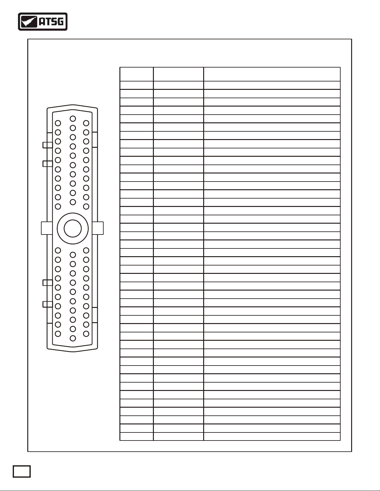
123
4
89101112
13
17181920
212223
141516
567
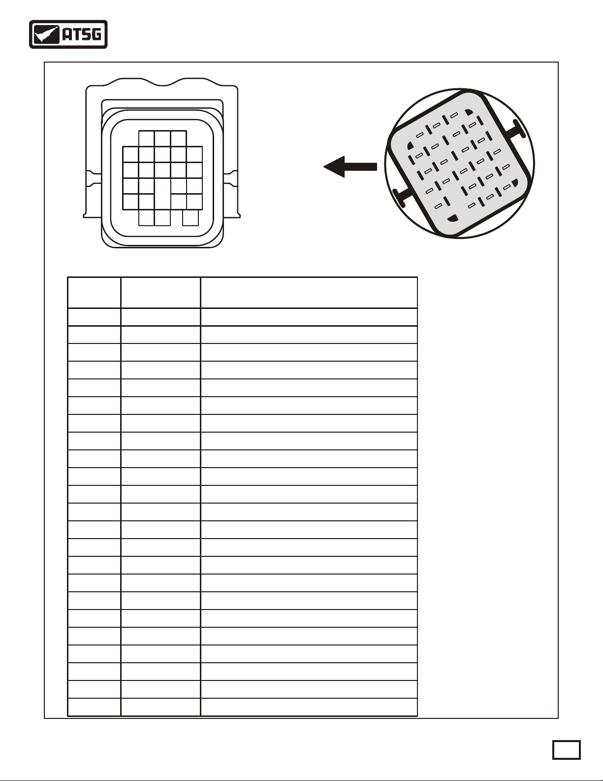
PIN
CAVITY WIRE
COLOR FUNCTION
White/Tan
White
Violet/White
Violet/Black
Tan/Black
Orange/Black
Violet
Violet/Lt. Green
Violet
Red
Pink
Gray
Dk. Green/White
Dk. Blue
Dk. Blue/Black
Yellow/Dk. Blue
White/Dk. Blue
Brown/Yellow
Brown
Brown/Lt. Blue
Lt. Blue
Lt. Green
Lt. Green/Black
Fused Ignition Switch Battery Voltage
LR/TC Clutch Solenoid Control
Overdrive Clutch Solenoid Control
Line Pressure Control Solenoid Control
Underdrive Clutch Solenoid Control
4th Clutch Solenoid Control
2nd Clutch Solenoid Control
Multi-Select Solenoid Control
Speed Sensor Ground
Transmission Oil Temperature Sensor Signal
Transmission Control Relay Output
4th Clutch Pressure Switch Signal
2nd Clutch Pressure Switch Signal
Low/Reverse Clutch Pressure Switch Signal
Overdrive Clutch Pressure Switch Signal
Underdrive Clutch Pressure Switch Signal
Park/Neutral Position Switch Signal
Transmission Range Sensor (T41) Signal
Transmission Range Sensor (T42) Signal
Back-Up Lamp Feed
Transmission Range Sensor (T3) Signal
Transmission Range Sensor (T1) Signal
Transmission Range Sensor (T2) Signal
1
2
3
4
5
6
7
8
9
10
11
12
13
14
15
16
17
18
19
20
21
22
23
23-WAY CASE CONNECTOR PIN CAVITY IDENTIFICATION AND FUNCTION
Figure 7
1
4
8
5
9
6
10
11
12
13
17
14
18
15
19
16
20
212223
7
2
3
Vehicle Harness Connector Transmission
Case Connector
"Front"
Copyright © 1999 ATSG
AKPPHELP.RU Руководство по ремонту АКПП
12
AUTOMATIC TRANSMISSION SERVICE GROUP
Technical Service Information
Copyright © 1999 ATSG
1
2
3
4
5
6
7
8
9
10
11
12
13
14
15
16
17
18
19
20
41
42
43
44
45
46
47
48
49
50
51
52
53
54
55
56
57
58
59
60
21
22
23
24
25
26
27
28
29
30
31
32
33
34
35
36
37
38
39
40
PIN
CAVITY WIRE
COLOR FUNCTION
Lt. Green/Black
Lt. Green/White
Tan/Black
Violet
Pink
Pink/Yellow
Gray/Black
Orange/Black
Yellow/Dk.Green
Red/White
Brown
Violet/Lt. Green
Violet/White
Lt. Green
Violet/Tan
Violet/White
Yellow/Violet
White
Violet
Red
Red
Red
Red
Pink
Gray
Gray/Lt. Blue
Dk. Green/White
Dk. Blue
Dk. Blue/Black
Yellow/Dk. Blue
Orange/Dk. Blue
White/Dk. Blue
Brown
Brown/Lt. Blue
Black/Lt. Blue
Red/Black
Black/Yellow
Black/Yellow
Black/Yellow
Black/Red
Lt. Blue
Lt. Green
White/Orange
Transmission Range Sensor T1 Signal
Transmission Range Sensor T3 Signal
Crankshaft Position Sensor Signal
Back-up Lamp Relay Control
Overdrive Clutch Solenoid Control
Line Pressure Control Solenoid Control
Underdrive Clutch Solenoid Control
4th Clutch Solenoid Control
Overdrive Clutch Solenoid Control
2nd Clutch Solenoid Control
L/R-TCC Clutch Solenoid Control
Multi-Select Solenoid Control
Speed Sensor Ground
Output Speed Sensor Signal
Vehicle Speed Sensor Signal
Transmission Oil Temperature Sensor Signal
Transmission Control Relay Output
Transmission Control Relay Control
Transmission Control Relay Output
Transmission Control Relay Output
Ground
Ground
Ground
Ground
PCI Bus
SCI Recieve
5 Volt Supply
4th Clutch Pressure Switch Signal
Overdrive Off Switch Signal
2nd Clutch Pressure Switch Signal
Low/Reverse Clutch Pressure Switch Signal
Sensor Ground
Input Speed Sensor Signal
Overdrive Clutch Pressure Switch Signal
Torque Management Request
Underdrive Clutch Pressure Switch Signal
Line Pressure Sensor Signal
Transmission Range Sensor (T42) Signal
Transmission Range Sensor (T41) Signal
SCI Transmit
Fused Ignition Switch Output (Start)
Fused Ignition Switch Output (Start-Run)
Fused Battery Voltage
1
2
3
6
7
9
8
10
11
12
13
14
15
16
17
18
19
20
36
37
38
39
40
41
42
43
46
47
48
49
50
51
52
53
54
55
56
57
59
60
29
30
28
60-WAY CONNECTOR PIN CAVITY IDENTIFICATION AND FUNCTION
Figure 8
AKPPHELP.RU Руководство по ремонту АКПП

AUTOMATIC TRANSMISSION SERVICE GROUP
Technical Service Information
13
L/R
Pressure
Switch
2nd Clut
Pressure
Switch
OD
Pressure
Switch
4th Clut
Pressure
Switch
UD
Pressure
Switch
TRS
T42
Signal
Back-Up
Lamp
Switch
TRS
T41
Signal
TRS
T3
Signal
TRS
T2
Signal
TRS
T1
Signal
Line
Pressure
Sensor
Signal
5 Volt
Supply
Ground
Pressure Sensor
Multi-Select
Solenoid
Underdrive
Solenoid
Overdrive
Solenoid
2nd Clutch
Solenoid
4th Clutch
Solenoid
LR/TCC
Solenoid
Pressure
Control
Solenoid
Starter
Relay Ignition
Switch
12V
Output
Speed
Sensor
Input
Speed
Sensor
POWER DISTRIBUTION CENTER
TRANSMISSION
CONTROL RELAY
FUSE 5
30A
10 1217 721 23 2220 19 18 16 15 14 138 9 4 3 5 1 6112
TRANSMISSION CONTROL MODULE
16 15 53 38 301736
40 55 60 19 59 20 53
18 3929 3748 5747 50 3 2 1 41 42 549
52 13 14
TFT
Sensor
Copyright © 1999 ATSG
Back-up
Lamps
Figure 9
AKPPHELP.RU Руководство по ремонту АКПП
14
AUTOMATIC TRANSMISSION SERVICE GROUP
Technical Service Information
Copyright © 1999 ATSG
Spare
Relay Spare
Relay
Horn
Relay
AC
Clutch
Relay
Wiper
On/Off
Relay
Wiper
Hi/Lo
Relay
Heater
Relay
Down-
Stream
Heater
Relay
Up-
Stream
Starter
Relay
Fuel
Pump
Relay
Automatic
Shutdown
Relay
Transmission
Control
Relay
Fuse 5
(30A)
TRANSMISSION CONTROL RELAY AND FUSE LOCATIONS
POWER DISTRIBUTION CENTER
Figure 10
AKPPHELP.RU Руководство по ремонту АКПП
243810187P52119099AA
TITTJ243810187
P52119099AA 45RF AA
099
AUTOMATIC TRANSMISSION SERVICE GROUP
Technical Service Information
15
INPUT SPEED
SENSOR
LINE PRESSURE
SENSOR FROM COOLER LOCK-UP "ON"
PRESSURE
LOCK-UP "OFF"
PRESSURE
OUTPUT SPEED
SENSOR
Figure 11
TO COOLER
Copyright © 1999 ATSG
AKPPHELP.RU Руководство по ремонту АКПП

16
AUTOMATIC TRANSMISSION SERVICE GROUP
Technical Service Information
Copyright © 1999 ATSG
VALVE BODY
MANDATORY TOOLS NEEDED FOR CHECKING PRESSURES ON 45RFE
Pressure Tap Adapter Tool No. 8258, to check oil
pressuresthroughthevalve bodytaps.
Line Pressure Adapter Tool No. 8259, to install into the
line pressure sensor circuit, and then reinstall the
sensorandpressuregage.
l
l
l
l
l
l
l
l
l
l
l
l
l
l
l
l
l
l
l
l
l
l
l
l
l
l
l
l
l
l
l
l
l
l
l
l
l
l
l
l
l
l
l
l
l
l
l
l
l
Figure 12
4799655
05111
AK
1
98
Overdrive Clutch
Pressure
Low/Reverse
Clutch Pressure
Line Pressure
4th Clutch
Pressure 2nd Clutch
Pressure
Underdrive Clutch
Pressure
Reverse Clutch
Pressure
AKPPHELP.RU Руководство по ремонту АКПП

AUTOMATIC TRANSMISSION SERVICE GROUP
Technical Service Information
17
Copyright © 1999 ATSG
Low/Reverse
Clutch
2nd Clutch 4th Clutch
COOLER FILTER
COOLER FILTER
BYPASS VALVE
Overdrive
Clutch
Underdrive
Clutch
Reverse
Clutch
Figure 13
243810187P52119099AA
TITTJ243810187
P52119099AA 45RF AA
099
AIR PRESSURE TESTS
AKPPHELP.RU Руководство по ремонту АКПП

Figure 14
3000 5%
3000 5%
3000 5%
3000 5%
T2
T1
T3
T42
T41
AUTOMATIC TRANSMISSION SERVICE GROUP
Technical Service Information
18
Copyright © 1999 ATSG
TRS/SOLENOID BODY TESTS
TRANSMISSION RANGE SENSOR CHART
CIRCUIT METER P R N OD 2 1
C
C
C
C = Closed O = Open
C C
C C
C
C
C
C
C
CO O
O
O O
OOO
O O
O O
O
O
O
O OT41
T42
T3
T1
T2
T41 & GRD OR CONNECTOR PIN 4 & GRD
T42 & GRD OR CONNECTOR PIN 5 & GRD
T3 & GRD OR CONNECTOR PIN 8 & GRD
T1 & GRD OR CONNECTOR PIN 9 & GRD
T2 & GRD OR CONNECTOR PIN 13 & GRD
SOLENOID RESISTANCE CHART
RESISTANCESOLENOID
LR/TCC 10 AND 2
10 AND 7
10 AND 17
10 AND 20
10 AND 19
10 AND 21
10 AND 12
22 AND 23
OVERDRIVE
UNDERDRIVE
2ND CLUTCH
4TH CLUTCH
MULTI-SELECT
LINE PRESSURE
TOT SENSOR
CONNECTOR PINS
1.9 W@ 72°F
1.9 W@ 72°F
1.9 W@ 72°F
1.9 W@ 72°F
1.9 W@ 72°F
1.9 W@ 72°F
4.3 W@ 72°F
9.37k W@ 72°F
AKPPHELP.RU Руководство по ремонту АКПП
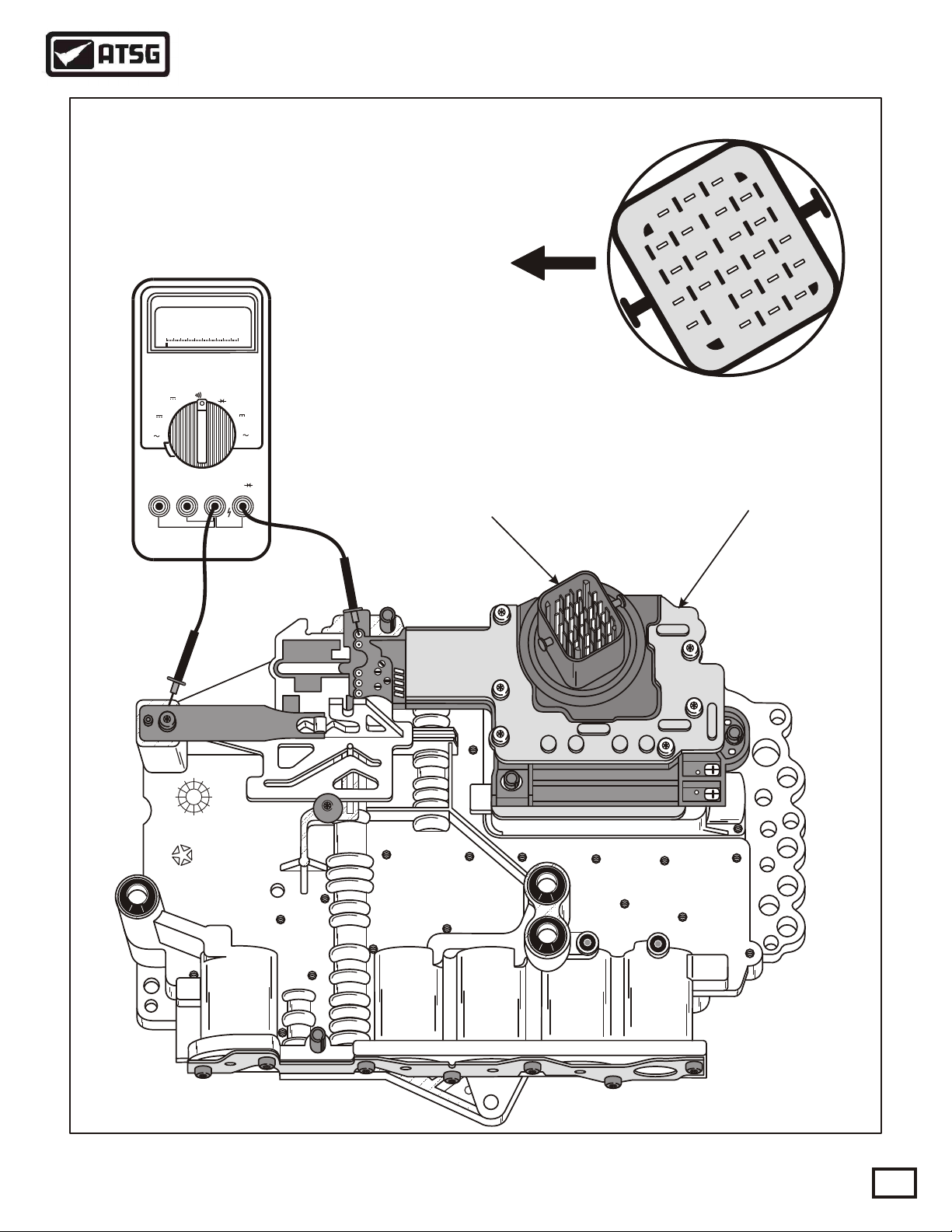
Figure 15
AUTOMATIC TRANSMISSION SERVICE GROUP
Technical Service Information
19
Copyright © 1999 ATSG
4799591
97
23-WAY
CONNECTOR
TRANSMISSION RANGE SENSOR
AND SOLENOID BODY ASSEMBLY
1
4
8
5
9
6
10
11
12
13
17
14
18
15
19
16
20
2122
23
7
2
3
Transmission
Case Connector
"Front"
WW
0.1
OFF
RPM
RPMCOMmAA
V
V
mV WW
WW
VmA
A
mA
A
Meter shown checking T41 Circuit
and should correspond with chart
in Figure 14. Solenoid tests must
be made thru case connector pins.
AKPPHELP.RU Руководство по ремонту АКПП

45RFE OBDII DIAGNOSTIC TROUBLE CODE LIST
Description
Check Shifter Signal (28)
Bus Communication (19)
Internal TCM (11, 13)
Internal TCM (17)
Internal TCM (16)
Input Speed Sensor Error (56)
Output Speed Sensor Error (57)
Engine Speed Sensor Circuit Error (18)
Gear Ratio Error In 1st Gear (51)
Gear Ratio Error In 2nd Gear (52)
Gear Ratio Error In 3rd Gear (53)
Gear Ratio Error In 4th Gear (54)
Gear Ratio Error In Reverse (50)
Torque Converter Clutch Control Circuit (38)
Low/Reverse Solenoid Circuit Error (C1)
2nd Clutch Solenoid Circuit Error (C2)
Overdrive Solenoid Circuit Error (C3)
4th Clutch Solenoid Circuit Error (C4)
Line Pressure Out Of Range (C8)
Restricted Port In T3 Range (65)
Line Pressure Low (C9)
Line Pressure High (CB)
Underdrive Hydraulic Pressure Test Failure (BO)
Underdrive Pressure Switch Sense Circuit (90)
4th Clutch Pressure Switch Sense Circuit (88)
2nd Clutch Pressure Switch Sense Circuit (82)
4th Clutch Hydraulic Pressure Test Failure (A8)
2nd Clutch Hydraulic Pressure Test Failure (A2)
Line Pressure Sensor Voltage Out Of Range (CA)
Underdrive Solenoid Circuit Error (C5)
Speed Ratio Error 2nd Prime (55)
Inadequate Element Volume 4th Clutch (64)
P0120
P0600
P0705
P0700
P0604
P0605
P1715
P1735
P0715
P0720
P0725
P0731
P0732
P0733
P0734
P0736
P0740
P0750
P0755
P0760
P0765
P0770
P1720
P1721
P1722
P1724
P1726
P1727
P1728
P1732
P1733
P1734
P1736
NO
NO
NO
NO
NO
NO
NO
NO
NO
NO
NO
NO
YES
YES
YES
YES
YES
YES
YES
YES
YES
YES
YES
YES
YES
YES
YES
YES
YES
YES
YES
YES
YES*
YES*
YES
YES**
YES**
YES**
YES**
YES**
YES**
YES**
YES**
YES
YES
YES
YES
YES
YES
YES
YES
YES
YES
YES
YES
YES
YES
YES
YES**
NO
NO
NO
NO
NO
NO
NO
Throttle Position Signal Out Of Range (29)
Limp-in MIL Illumination
OBDII
Codes
Figure 16
AUTOMATIC TRANSMISSION SERVICE GROUP
Technical Service Information
20
Copyright © 1999 ATSG
Multi-Select Solenoid Circuit Error (C6)P1737 YES YES
AKPPHELP.RU Руководство по ремонту АКПП
Table of contents
Other ATSG Microphone System manuals


