ATSG FORD 4R100 User manual

INDEX
Copyright © ATSG 2003
FORD 4R100
IDENTIFICATION TAG LOCATIONAND INFORMATION ............................................................... 3
GENERAL DESCRIPTION AND OPERATION ..................................................................................... 4
COMPONENT AND SOLENOID APPLICATION CHART ................................................................... 5
"PTO" GENERAL REQUIREMENTS .................................................................................................... 6
ELECTRICAL COMPONENT DIAGNOSIS ........................................................................................... 8
FLUID REQUIREMENTS ....................................................................................................................... 12
SOLENOID PACK TESTING .................................................................................................................. 12
ABBREVIATION DESCRIPTION .......................................................................................................... 14
DIAGNOSTIC TROUBLE CODE CHART AND DESCRIPTION ........................................................ 15
LINE PRESSURE TEST .......................................................................................................................... 21
NON-PTOAND PTO HYDRAULIC DIFFERENCES ........................................................................... 22
PWM AND NON-PWM OIL PUMP DIFFERENCES ........................................................................... 34
CASE CHECKBALL LOCATIONS ......................................................................................................... 38
VALVE BODY CHECKBALLLOCATIONS ........................................................................................... 39
AIR PRESSURE CHECKS ...................................................................................................................... 40
TRANSMISSION DISASSEMBLY ......................................................................................................... 41
COMPONENT REBUILD SECTION
TRANSMISSION CASE ASSEMBLY ................................................................................................ 55
FRONT AND REAR PLANETARY CARRIERS ............................................................................... 64
FORWARD CLUTCH HOUSING ...................................................................................................... 66
DIRECT CLUTCH HOUSING ........................................................................................................... 69
FORWARD, DIRECT, SUN SHELL SUB-ASSEMBLY .................................................................... 76
CENTER SUPPORT ASSEMBLY ...................................................................................................... 80
INTERMEDIATE/OVERDRIVE CYLINDER ASSEMBLY ............................................................. 82
OVERDRIVE GEARSET ASSEMBLY ............................................................................................... 84
COAST CLUTCH HOUSING DIFFERENCES ................................................................................ 88
COAST CLUTCH HOUSING ASSEMBLY ........................................................................................ 90
OIL PUMP ASSEMBLY ...................................................................................................................... 94
VALVE BODY ASSEMBLY ............................................................................................................... 100
TRANSMISSION FINAL ASSEMBLY ................................................................................................. 102
MANUAL VALVE CHECK .................................................................................................................... 111
MANUAL SHIFT LEVER DIFFERENCES ........................................................................................ 112
TORQUE SPECIFICATIONS ............................................................................................................... 115
VALVE BODY BOLT CHART AND IDENTIFICATION .................................................................... 116
BOLT CHARTAND IDENTIFICATION ............................................................................................. 117
SPECIAL SERVICE TOOLS ................................................................................................................. 118
AUTOMATIC TRANSMISSION SERVICE GROUP
18639 S.W. 107TH AVENUE
MIAMI, FLORIDA 33157
(305) 670-4161

INTRODUCTION
FORD 4R100
DALE ENGLAND
FIELD SERVICE CONSULTANT
ED KRUSE
TECHNICAL CONSULTANT
WAYNE COLONNA
TECHNICAL SUPERVISOR
PETER LUBAN
TECHNICAL CONSULTANT
JIM DIAL
TECHNICAL CONSULTANT
GREGORY LIPNICK
TECHNICAL CONSULTANT
JERRY GOTT
TECHNICAL CONSULTANT
JON GLATSTEIN
TECHNICAL CONSULTANT DAVID CHALKER
TECHNICAL CONSULTANT
ROLAND ALVAREZ
TECHNICAL CONSULTANT
MIKE SOUZA
TECHNICAL CONSULTANT
GERALD CAMPBELL
TECHNICAL CONSULTANT
1
NopartofanyATSGpublicationmaybereproduced,storedinanyretrievalsystemortransmittedinanyformor
by any means, including but not limited to electronic, mechanical, photocopying, recording or otherwise,
without written permission of Automatic Transmission Service Group. This includes all text illustrations,
tablesandcharts.
The information and part numbers contained in this booklet have
been carefully compiled from industry sources known for their
reliability, but ATSG does not guarantee its accuracy.
Copyright © ATSG 2003
Updated
October, 2003
The Ford 4R100 transmission is an updated version of the E4OD and was first introduced in the 1999 model
year,andiscurrentlyfoundintheF250,F350,F450andF550SuperDutytrucks,E150,E250,E350,E450vans
andthe Expedition/Navigator/Excursion vehiclesequipped with the5.4L, 6.8L, and7.3Lengines. Some of the
4R100 units are equipped with a Power-Take-Off (PTO) window on the left hand side of the transmission case.
The revisions in the 4R100 have created many new engineering changes that have affected many of the internal
andexternalpartsthatwillaffecttheservicing,repairingandoverhauloftheseunits.
We wish to thank Ford Motor Company
for the information and illustrations
that have made this booklet possible.
AUTOMATIC TRANSMISSION SERVICE GROUP
18639 S.W. 107TH AVENUE
MIAMI, FLORIDA 33157
(305) 670-4161

3
AUTOMATIC TRANSMISSION SERVICE GROUP
Technical ServiceInformation
Copyright © 2003 ATSG
RFF81P-7006-BA
Ford
Ford
Ford
98
XW4P-AC
RJL-B
004361
BD-9C17
17C9BD-
Build
Date
Year Month Day
9=1999
0=2000
1=2001
2=2002
3=2003
A=Jan
B=Feb
C=Mar
D=Apr
E=May
F=Jun
G=Jul
H=Aug
J=Sep
K=Oct
L=Nov
M=Dec
XW4P-AC
55GG
RJL-B
BD-9C17
004361
0043616520
4 X 44 X 4
1
2
3
4
Build Date (Year, Month, Day)
Serial Number
Transmission Model
Assembly Part Number, PrefixAnd Suffix1
2
3
4
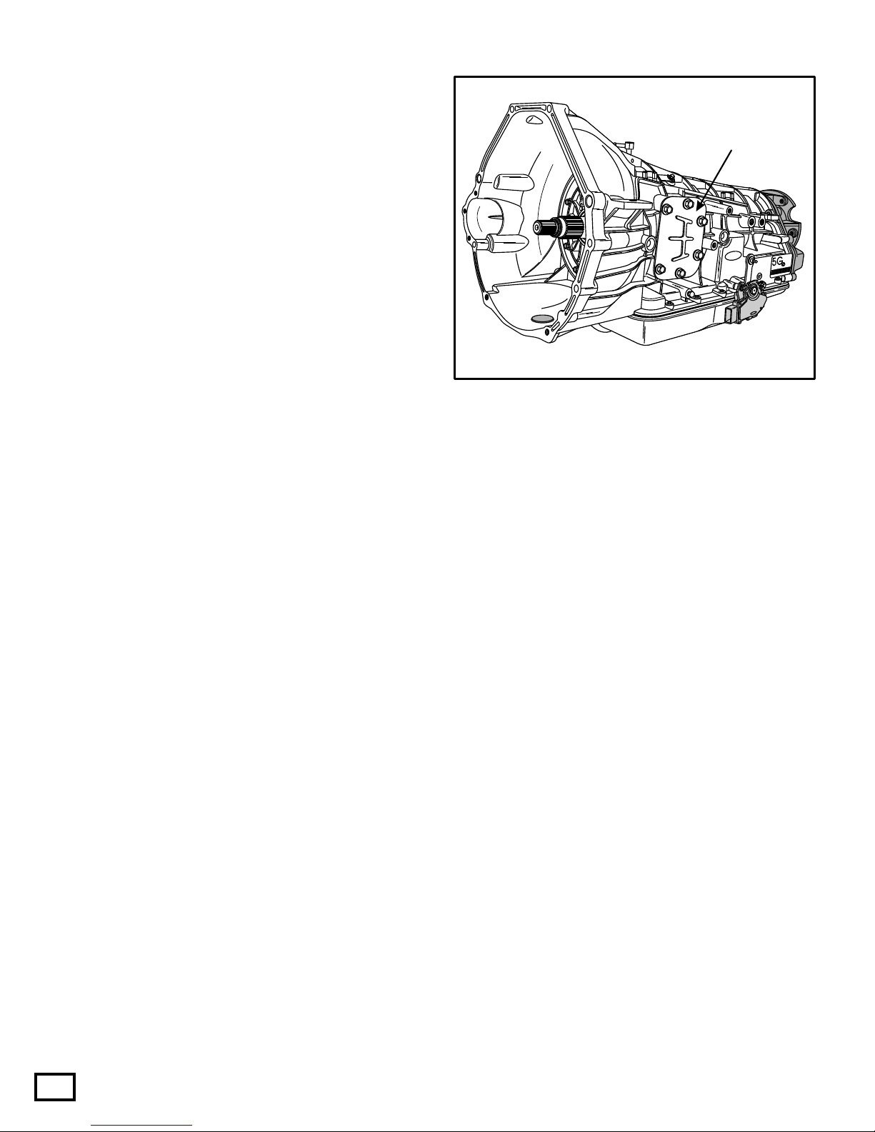
TRANSMISSION IDENTIFICATION
WITH POWER TAKE OFF OPTION
PTO is available as an option on 8500 GVW or above, Super Duty
F-Seriestruckswith6.8Lgasolineand7.3LDieselengines.
Ford4R100transmissionsonothermodelsarenotPTOcapable.
Note:
Figure 1

AUTOMATIC TRANSMISSION SERVICE GROUP
Technical ServiceInformation
4
Copyright © 2003 ATSG
TRANSMISSION
DESCRIPTION AND OPERATION
General Description
Shift Quadrant Indicator
Major Internal Components
"Seven Friction Apply Elements"
"Three One-Way Clutches"
"Three Simple Planetary Gearsets"
"Typical" Shift Quadrant Indicator
The Ford 4R100 automatic transmission is a four
forward speed unit with electronic shift control. It is
designed for longitudinal powertrains for rear wheel
drivevehicles.
The 4R100 transmission features a four element
torque converter design that includes Torque
ConverterClutch(TCC)anda gear train that includes
threeplanetarygearsets.
Some models provide for Power Take Off (PTO)
operation in all transmission shift lever positions.
DuringPTOoperationinOD,4thgearisdisabled.
The hydraulic control system of the 4R100 unit has
fiveelectronicallycontrolledsolenoidsfor:
Shiftfeel,throughlinepressurecontrol.
Shiftscheduling,throughshiftvalveposition.
Enginebrakingduringcoastconditions.
TCCapply(On/OfforModulating).
IntermediateBand
CoastClutch,Multi-disc
OverdriveClutch,Multi-disc
IntermediateClutch,Multi-disc
DirectClutch,Multi-disc
ForwardClutch,Multi-disc
Low/ReverseClutch,Multi-disc
OverdriveRollerClutch
IntermediateSprag
LowRollerClutch
Overdrive
Forward
Reverse
P R N D2 1
Figure 2 Figure 3
Vehiclesequippedwiththe4R100transmissionhave
aTransmissionControlSwitch(TCS),alsoreferredto
as "Overdrive Cancel Switch", and a Transmission
Control Indicator Lamp (TCIL), located on the end of
themanualgear shiftlever,as showninFigure 3. The
TCS is a momentary contact switch. When this
switch is pressed, a signal is sent to the PCM to allow
automaticshiftsfrom 1st to4thgearor from 1stto3rd
gear. After the TCS has been pressed the PCM turns
on the TCIL lamp ("OFF"), to indicate that overdrive
hasbeencanceled,asshowninFigure3.
OVERDRIVE OFFOVERDRIVE OFF
TCS
SWITCH
TCIL LAMP
The shift quadrant has the following positions, as
showninFigure2: P,R,N,D,2and1.
Dposition (TCS OFF) provides 1-2-3-4 automatic
upshifts and downshifts. Coast braking occurs in 4th
gear. (TCILNotIlluminated)
Dposition (TCS ON) provides 1-2-3 automatic
upshifts and downshifts. Coast braking occurs in 3rd
gear. (TCILIlluminated)
2position provides a pull-in shift to 3rd gear with
coast braking. After an automatic downshift, a 2nd
gearholdoccurswithcoastbraking.
1 position provides a pull-in shift to 2nd gear with
coast braking. After an automatic downshift, a 1st
gearholdoccurswithcoastbraking.
AUTOMATIC TRANSMISSION SERVICE GROUP
Technical ServiceInformation
5
Copyright © 2003 ATSG
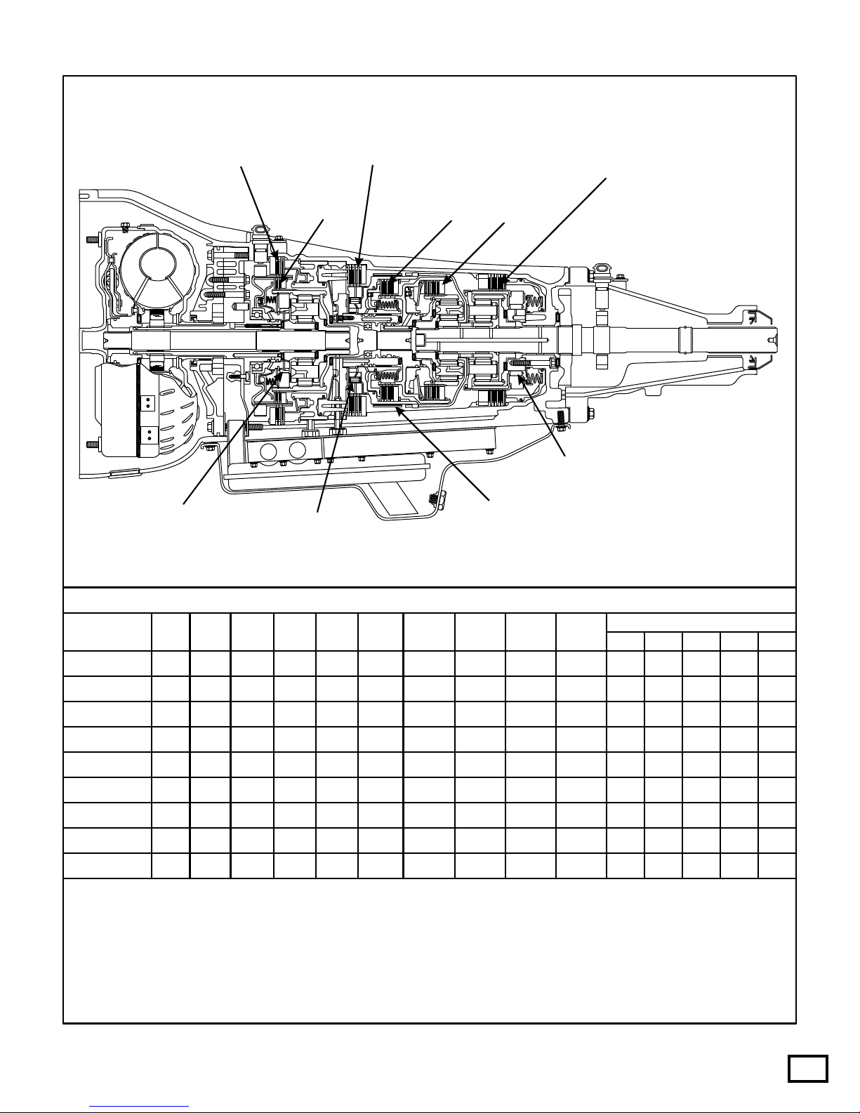
FORD MOTOR COMPANY
4R100 ("PTO" Version Illustrated)
Reverse - 2.18
GEAR RATIOS
Overdrive
Clutch
Overdrive
Roller Clutch
Intermediate
Clutch
Intermediate
Band
Intermediate
Sprag
Coast
Clutch Forward
Clutch
Direct
Clutch
Low/Reverse
Clutch
Low
Roller Clutch 1st Gear - 2.71
2nd Gear - 1.54
3rd Gear - 1.00
4th Gear - 0.71
Fwd
Clut
ON Hold
Hold
Hold
Hold
Hold Hold
Hold
Hold
Hold
Hold
Hold
ON ON
ON
ON
ON
ON
ON
ON
ON
ON
ON
ON ON
On
On
On *On
*On
*On
*On
*On
*On
On
On
On
On
On
On On
On
Mod
Mod
Mod
Mod
Mod
Mod
Mod
Mod
ModOn
On
Off Off
Off Off Off
Off
Off
Off
*Off
*Off
*Off
Off
Off
Off
Off
Off
Off
ON
ON ON
ON
ON ON
ON
ON
ON
ON
Int
Clut Int
Band O.D.
Roller Low
Roller SS1 SS2 CCS
SOLENOIDS
TCC EPC
Int
Sprag
Dir
Clut O.D.
Clut Cst
Clut L/R
Clut
Park/Neut
Reverse
OD-2nd
OD-3rd
OD-3rd**
OD-3rd** = TCS "On" with TCIL illuminated showing "Off"
OD-4th
M-2nd
M-1st
OD-1st
GEAR
COMPONENT AND SOLENOID APPLICATION CHART
*On=IfthePCMdeterminesthatpowertrainoperatingconditionsexistforTCCapply,theTCCsolenoidmay
beOn(ModulatingwithPWMTCCunits)inanyforwardgearexceptManual1st.
*Off=Willbe"On",iftheTCSswitchispushed.
Mod=ModulatingatalltimesbythePCMandlinepressurewillberegulatedbasedonthrottleposition,
engineloadandvehiclespeed.
Figure 4
AUTOMATIC TRANSMISSION SERVICE GROUP
Technical ServiceInformation
6
Copyright © 2003 ATSG
PTO "GENERAL" REQUIREMENTS:
RFF81P-7006-BA
Ford
FordFord
98
XW4P-AC
RJL-B
004361
BD-9C17
PTO
Window
Figure 5
(1)Obviously the case must be PTO capable with
the cast-in window in the transmission where the
PTOunitmountstothetransmission,asshownin
Figure5.
(2)Designed for use during Mobile (Some Models)
orStationaryconditions.
Shift Solenoid 2 and the Coast Clutch Solenoid
mustbeenergizedwhenthePTOisturnedON.
(3)PTOisavailableasanoptiononlyon 8500GVW
or above, Super Duty F-Series trucks with 6.8L
Gasoline and 7.3L Diesel engines. Ford 4R100
transmissions on other models are not PTO
capable.
(4)
(5)
Battery voltage must be supplied to the
Powertrain Control Module (PCM) input pin 4
on gasoline models, or pin 66 on diesel models,
when the PTO is engaged. The processor uses
this information to raise EPC pressure to
approximately 55 PSI so that you do not burn the
coast clutch. This voltage must be provided by
thePTOinstaller.
"GENERAL" CONDITIONS FOR OPERATION
(1)
(2)
(3)
(4)
(5)
Thevehicleisnotinthecrankorstartmode.
The transmission range selector must be in the P,
R,O.D,2or1position. ThePTOwillnotoperate
whenselectorisintheneutralposition.
PTO operation is inhibited when in cranking
mode,neutral,or4thgear.
Transmission only operates 1st through 3rd
gears. Computer strategy does not allow 4th
geartoengage,underanyconditions.
Transmission Fluid Temperature Sensor (TFT)
readingmustbeuptooperatingtemperature.
Specific Operation For Diesel, See Page 7.
GASOLINE ENGINE PTO OPERATION:
(1)
(2)
(3)
(4)
PTO installer must obtain a "High Idle Throttle
Control"fromanaftermarketsource.
Auxiliary Powertrain Control Module seen on
Pageseven,doesnotworkonthegasolineengine
models. APCM module works only on the 7.3L
dieselengine.
For stationary PTO operation an engine idle
speedof1300RPMisrequired.
The Torque Converter Clutch (TCC) engages
oncetheenginereaches1300RPM.
TRANSMISSION FUNCTIONS
DURING PTO OPERATION:
(1)
(2)
(3)
(4)
(6)
(5)
Shift Solenoid 2 and Coast Clutch Solenoids are
turned on, the coast clutch activates and does not
allow4thgearoperationduringPTOoperation.
Electronic Pressure Control (EPC) pressure is
raised to approximately 55 PSI. This is why the
coast clutch will be smoked in a short period of
time if a battery voltage wire is not supplied to
EEC input pin 4 (gasoline) or pin 66 (diesel)
when the PTO is engaged, as this rise in pressure
wouldnotoccur.
The Transmission Control Indicator Lamp
(TCIL)illuminates.
When the PTO is turned ON, the transmission
operates only in 1st through 3rd gears.
Overdrive 4th gear is not allowed by the PCM
strategy.
PTO operation can cause transmission fluid
temperature to exceed the recommended
maximum limit of 250 degrees F. Failure mode
logicwithin PCMstrategypreventstransmission
damage by disabling the PTO above this
temperaturelimit.
The transmission shift schedule is earlyand shift
feelisveryfirm.
AUTOMATIC TRANSMISSION SERVICE GROUP
Technical ServiceInformation
7
Copyright © 2003 ATSG
FordFord
FordFord
RPM
CONTROL
RPM
CONTROL CHARGE
PROTECT
CHARGE
PROTECT POWERPOWER
2500
AUXILIARY POWERTRAIN CONTROL MODULEAUXILIARY POWERTRAIN CONTROL MODULE
CHARGE PROTECTION APPLICATION
KITS INCLUDE
RPM CONTROL
ChargeProtectionisusedformaintainingbatterycharge.
In Charge Protection mode, the battery voltage is monitored and the
engine idle speed is increased as necessary, so the battery charge is
maintainedasrequired.
Charge Protection can be activated from in-cab and can be
programmedtoactivateautomaticallyonenginestart-up.
Exclusivelyforlighttruckswiththe7.3LDieselEngine.
IntendedforStationaryUseOnly.
OrderGuideOptionCode961.
Aux.PowertrainControlModule.
MountingHardwareandBracket.
WiringHarness.
InstructionBooklet.
OperatorsCard.
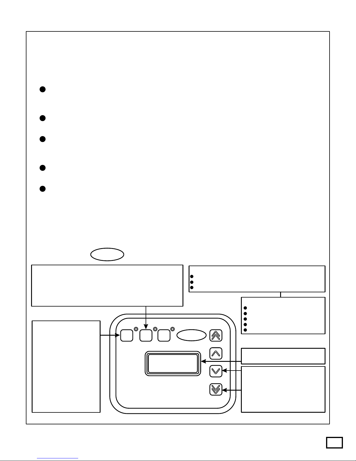
LCD screen displays the current
enginespeedorbatteryvoltage.
Each Single Arrow key contains a
preset speed allowing for four
programmableRPMsettings.
The Double Arrow keys can also be
used to manually raise or lower the
engine speed at a faster or slower
rate.
RPMControlisusedfor
This is the recommended
method of elevating idle
speedforPTOoperations.
RPM Control mode can be
activated from in-cab and
can be programmed to
activate automatically on
enginestart-up.
The programmable speed
presets range from 1300 to
"AUXILIARY" POWERTRAIN CONTROLMODULE
7.3L DIESELENGINE (ONLY)
The Auxiliary Powertrain Control Module (APCM) commands the Electronic Engine Control
(EEC) module to increase the idle speed during PTO operation. The APCM controls engine
speedfrom1300to2500RPM.
The Auxiliary Powertrain Control Module is a seperate option,it does not come standard with a
PTOcapabletransmission,andisfor7.3Ldieselapplicationsonly.
Intendedforstationaryuseonly,andinstationaryoperationthePTOrequiresanengineidlespeed
of 1300 RPM. During stationary PTO operation on the 7.3L diesel, the EEC increases the idle to
1300RPMautomatically.
During stationary PTO operation, the Torque Converter Clutch (TCC) engages once the RPM
reaches1200-1300RPM.
Thefollowingconditionsmustbemetbeforetheidlespeedisincreased:
1. Parkingbrakemustbeengagedforallapplications.
2. Nohydraulicbrakeactuation.
3. Acceleratorpedalmustbeintheidleposition.
4. VehiclespeedmustbezeroMPH.
5. Brakelightsmustbefunctional.
DIESEL ENGINE PTO OPERATION:
Figure 6
DIAGNOSTIC CONCERNS WITH PTO
EQUIPPED VEHICLES:
ELECTRICAL COMPONENT DIAGNOSIS
(1)
(2)
(3)
(4)
Always ensure that PTO is turned OFF, before
anydiagnosticproceduresbegin.
Never perform any transmission special tests
(i.e.pressuretest,stalltestetc.)whenthePTO is
turnedON.
If a transmission concern or symptom goes
away with the PTO turned OFF, it is most likely
notatransmissionconcern.
On Board Diagnostics operate normally during
PTO operation with the exception of the engine
misfiremonitor. Thecircuitchecksmadebythe
PCM and Failure Mode Effect Management
(FMEM) capability will continue. The PTO
must be turned OFF to access Diagnostic
TroubleCodes(DTC's)andperformOBDtests.
Caution: If the batteries are disconnected for any
reason,thePCM"must"havea 7 mile drivecycleat
speeds above 50 MPH, before it remembers that it is
capableofrunningaPTO
AUTOMATIC TRANSMISSION SERVICE GROUP
Technical ServiceInformation
8
Copyright © 2003 ATSG
Accelerator Pedal Position Sensor (Diesel Only)
4X4 Low Switch
The Accelerator Pedal (AP) position sensor is
mounted on the accelerator pedal inside the vehicle
and detects the position of the accelerator pedal and
sends this information as a varying voltage signal to
the PCM. The PCM then uses the monitored voltage
level of the APsensor for control of EPC pressure and
shiftscheduling.
The Idle Validation Switch is fed voltage through
fuse number 19, as well as the Transmission Control
Switch,asshowninFigure7.
If the Idle Validation Switch feed voltage is lost for
any reason, the engine will immediately return to
idleandstaythereuntil feedvoltageisrestored.
FUSE 19
Red/Yellow
Transmission Control Switch (TCS)
Clutch Pedal Position (CPP) (Std Trans Only)
Idle Validation Switch (IVS) (Diesel Only)
Overhead Trip Computer Module
Generic Electronic Module (GEM)
Instrument Cluster TerminalA12
Instrument Cluster Terminal B11
CENTRAL JUNCTION BOX
Figure 7
Figure 8
The 4X4 Low Switch is used to the PCM that the
transfer case system is operating in LOW range. The
PCM receives the 4X4 Low Switch input signal and
modifies shift scheduling for the lower gear ratio
(SeeFigure8).
If the 4X4 LOW indicator fuse is blown, the
transmission will shift according to the 4X4 LOW
shift schedule, regardless of transfer case lever
position. PCM PIN 14
Lt. Blue/Black

AUTOMATIC TRANSMISSION SERVICE GROUP
Technical ServiceInformation
9
Copyright © 2003 ATSG
Copyright © 2003 ATSG
Turbine Shaft Speed Sensor
PTO Models Only = 496-1244 Ohms Resistance
Part Number F81Z-7M101-BA
Non PTO Models Only = 781-1979 Ohms Resistance
Part Number F81Z-7M101-AA
Copyright © 2003 ATSG
Output Shaft Speed Sensor
All Models = 781-1979 Ohms Resistance
Part Number F81Z-7M101-AA
Turbine Shaft Speed Sensor Output Shaft Speed Sensor
The Output Shaft Speed (OSS) sensor is a magnetic
pickup that sends the PCM a frequency signal related
totherotatingspeedofthetransmissionoutputshaft.
The OSS sensor was added to the top of extension
housing, as shown in Figure 10. The OSS is triggered
by an added rotor pressed onto the output shaft. The
park gear is also now pressed onto the output shaft,
and the number 13 thrust washer has changed to a
thrust bearing, as shown in Figure 11. We have
provided you with the resistance reading and the
OEM part number for the output shaft speed sensor.
Refer to Figure 10 for output shaft speed sensor
information.
The PCM uses the OSS sensor signal to control EPC
pressure,shiftschedulingandTCCstrategy.
The Turbine Shaft Speed (TSS) sensor is a magnetic
pickup that sends the PCM a frequency signal related
totherotatingspeedofthetransmissioninputshaft.
The TSS mounts on the top front of the case on some
models, as shown in Figure 9. We have also provided
you with the resistance readings and OEM part
numbers on both Turbine Speed Sensors, as the PTO
and Non-PTO models use different sensors, as shown
inFigure9.
The PCM uses the TSS sensor signal to control EPC
pressureandTCCstrategy.
Figure 9
Figure 10 Figure 11
The Park Gear is also a press fit to the output
shaft,andthe number13thrustwasher, between
the case and the park gear has been replaced
withaneedlebearing.
OSS Rotor Park Gear
(Press Fit)(Press Fit)

ELECTRICAL COMPONENT DIAGNOSIS DTR TESTING PROCEDURE
AUTOMATIC TRANSMISSION SERVICE GROUP
Technical ServiceInformation
10
Copyright © 2003 ATSG
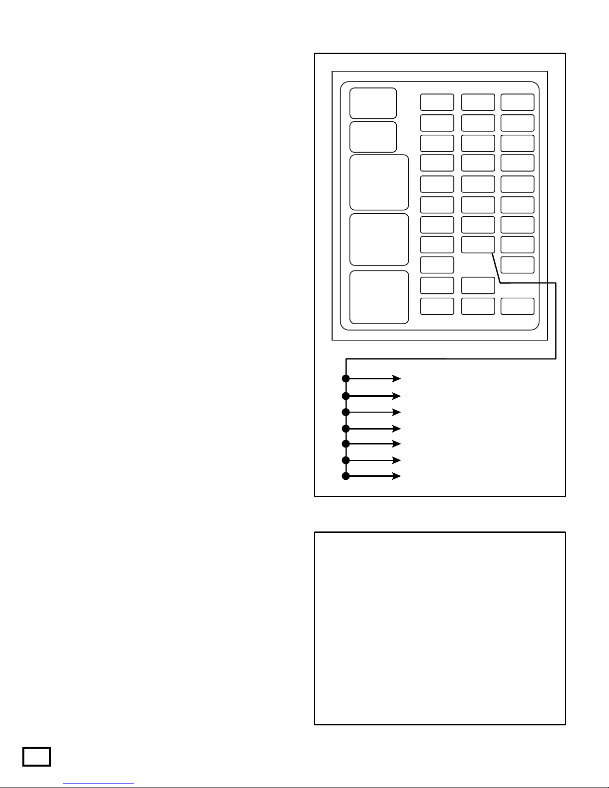
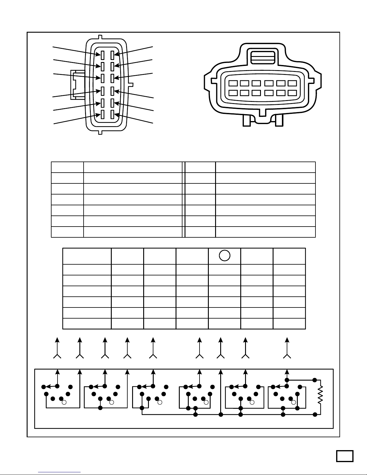
Digital Transmission Range Sensor
The Digital Transmission Range (DTR) sensor has a
twelve pin electrical connector and is located on the
outside of the transmission at the manual lever, as
showninFigure12.
The DTR sensor completes the start circuit in Park
and Neutral, the backup lamp circuit in Reverse, and
theneutralsensecircuit(4WDOnly)wheninNeutral.
The DTR sensor also opens or closes a set of four
different switches that are monitored by the
Powertrain Control Module (PCM) to determine the
positionofthetransmissionmanuallever. Referto
Figure13.
Figure 12
Ford
F7TP-7F293-AA
NEUTRAL
L
C
RFF81P-7006-BA
Ford
Ford
Ford
98
XW4P-AC
RJL-B
004361
BD-9C17
In Figure 13 we have provided you with pin number
identification for both the transmission range sensor
and the vehicle harness. We have also provided a
chart that will give you the open/closed state of each
internal switch, dependent on selector position, and
noticethatthreepositionsreada270W resistor,thatis
alsointernal.
Note: All testing that we have provided for you is
done with a DVOM, set to the ohms position, and all
tests are performed with the ignition switch in the
"OFF"position.
(1) Testing the transmission range 3A switch, and
the 270W internal resistor is done across pins 2
and3oftheDTRsensor,andmustbecheckedin
each selector position to determine the switch
andresistorintegrity. RefertoFigure13.
(2) Testing the transmission range 1 switch is done
across pins 2 and 4 of the DTR sensor, and must
be checked in each selector position to
determineswitchintegrity. RefertoFigure13.
(3)
(4)
(5)
(6)
Testing the transmission range 2 switch is done
across pins 2 and 5 of the DTR sensor, and must
be checked in each selector position to
determineswitchintegrity. RefertoFigure13.
Testing the transmission range 4 switch is done
across pins 2 and 6 of the DTR sensor, and must
be checked in each selector position to
determineswitchintegrity. RefertoFigure13.
Testing the reverse lamp circuit is done across
pins 9 and 11 of the DTR sensor, and must be
checked in each selector position to determine
switchintegrity. RefertoFigure13.
Testing the neutral start circuit is done across
pins 10 and 12 of the DTR sensor, and must be
checked in each selector position to determine
switchintegrity. RefertoFigure13.
AUTOMATIC TRANSMISSION SERVICE GROUP
Technical ServiceInformation
11
Copyright © 2003 ATSG
Figure 13
P R N 2 1TERMINALS
2 AND 3 CLOSED
CLOSED CLOSED CLOSED CLOSED
CLOSED
CLOSED
CLOSEDCLOSED
CLOSED
CLOSED
CLOSED
OPEN
OPEN
OPEN
OPEN OPEN
OPEN OPEN
OPEN
OPEN
OPEN OPEN
OPEN
OPEN
OPENOPEN
OPEN
OPEN
OPEN
CLOSED
CLOSED
CLOSED
2 AND 4
2 AND 5
2 AND 6
9 AND 11
10 AND 12
D
270 W270 W270 W
1 7
82
93
104
115
126
View looking into DTR Sensor
12 11 10 9 8
23456 1
7
View looking into DTR Sensor
harness connector-terminal side
P1
2R ND
P1
2R ND
P1
2R ND
P1
2R ND
P1
2R ND
P1
2R ND
270 W
9 11 12 10 4 5 6 32
DIGITALTRANSMISSION RANGE SENSOR
Pin No.
1
2
3
4
5
6
7
8
9
10
11
12
Pin No.Function
Not Used Ground
Neutral
Battery Voltage Feed
Fuse 21, Hot In Start
Back-up Lamps
Starter Relay
Signal Return (Ground)
TR3A (5 Volts from PCM)
TR1 (10-12 Volts from PCM)
TR2 (10-12 Volts from PCM)
TR4 (10-12 Volts from PCM)
Function

OnlyMotorcraftMercon®multi-purposeautomatic
transmission fluid XT-2-QDX or an equivalent
Mercon® fluid should be used in all Ford 4R100
transmissions. Before adding any fluid, ensure that it
isthecorrecttype.
Always use the transmission fluid level indicator
(Dipstick) to set the correct fluid level. Set the fluid
level at normal operating temperature which is 150°
to170°F,engineatidleinPark.
ELECTRICAL COMPONENT DIAGNOSIS SOLENOID PACK TESTING PROCEDURE
4R100 FLUID REQUIREMENTS
AUTOMATIC TRANSMISSION SERVICE GROUP
Technical ServiceInformation
12
Copyright © 2003 ATSG
Solenoid Assembly
Checking Fluid
The Solenoid Assembly is bolted to the case and
located inside the bottom pan. The Solenoid
Assembly contains shift solenoid 1, shift solenoid 2,
coast clutch solenoid, TCC solenoid, EPC solenoid
and the TFT sensor. The solenoids are not serviced
individually. Youmustreplacetheentireassembly,as
showninFigure14. Someof theseunitsareequipped
with an ON/OFF TCC solenoid and some are
equipped with a PWM TCC solenoid, so it is
importanttodeterminewhichyouhave.
Figure 15
Figure 14
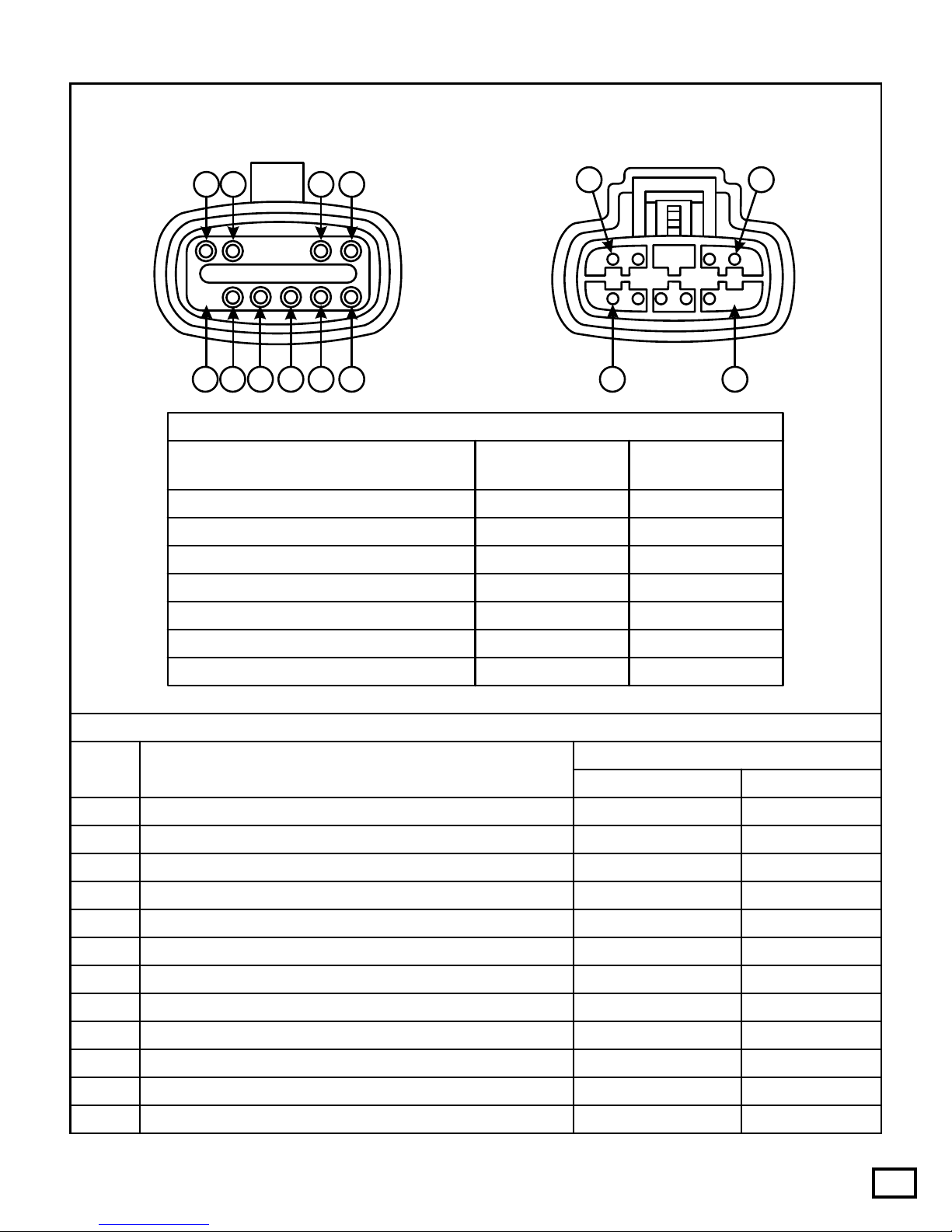
In Figure 16 we have provided you with pin number
identification for both the transmission case
connector and the vehicle harness. We have also
provided a chart that will give you the function of
each and the ohms readings you should see on each of
thesolenoidsandtheTFTsensor.
Note: All testing that we have provided for you is
done with a DVOM, set to the ohms position, and all
tests are performed with the ignition switch in the
"OFF"position.
(1) Shift Solenoid 1 is tested across pins 1 and 3,
and should read 20-30 ohms resistance. Refer
toFigure16.
Shift Solenoid 2 is tested across pins 1 and 2,
and should read 20-30 ohms resistance. Refer
toFigure16.
Coast Clutch Solenoid is tested across pins 1
and 5, and should read 20-30 ohms resistance.
RefertoFigure16.
EPC Solenoid is tested across pins 11 and 12,
and should read 3.0-5.0 ohms resistance. Refer
toFigure16.
TFT sensor is tested across pins 7 and 8. Refer
tothechartprovidedinFigure15.
TCCOn/OffSolenoidistestedacrosspins1and
4, and should read 20-30 ohms resistance.
RefertoFigure16.
TCC PWM Solenoid is tested across pins 1 and
4, and should read 10-20 ohms resistance.
RefertoFigure16.
(2)
(3)
(4)
(5)
(6)
(7)
Transmission Fluid Temperature
°C °F Resistance
-40 to -20
-19 to -1
0 - 20
21-40
41-70
71-90
91-110
111-130
131-150 267-302
-40 to -4
-3 to 31
32-68
69-104
105-158
159-194
195-230
231-266
1062k - 284k W
284k - 100k W
100k - 37k W
37k - 16k W
16k - 5k W
5k - 2.7k W
2.7k - 1.5k W
1.5k - 0.8k W
0.8k - 0.54k W
SOLENOID PACKASSEMBLY
AUTOMATIC TRANSMISSION SERVICE GROUP
Technical ServiceInformation
13
Figure 16
Solenoid Connector Pin Identification and Function
Gas & Diesel (Cal) Diesel (49 State)
PCM Connector Pin
DescriptionPin No.
1
2
3
4
5
6
7
8
9
10
11
12
Vehicle Power In For Solenoids (VPWR)
Vehicle Power In For EPC Solenoid (VPWR)
Electronic Pressure Control (EPC)
Shift Solenoid "B" (2) Ground from PCM
Shift Solenoid "A" (1) Ground from PCM
Converter Clutch Solenoid Ground from PCM
Coast Clutch Solenoid Ground from PCM
Transmission FluidTemp Sensor
Transmission FluidTemp Sensor (Signal Return)
Not Used
Not Used
Not Used
71, 97
71, 97
11
6
54
20
37
91
81
1
27
28
53
37
91
81
71, 97
71, 97
SOLENOID BODY
CONNECTOR
16 2345
121187
VEHICLE HARNESS
CONNECTOR
1
12 7
6
SOLENOID BODY PIN IDENTIFICATION AND FUNCTION
Solenoid Resistance Chart
Solenoid Body
Pin Numbers
Solenoid
Shift Solenoid "B" (2) 1 and 2 20-30 Ohms
20-30 Ohms
20-30 Ohms
10-20 Ohms
20-30 Ohms
3.0-5.0 Ohms
See Chart Below
1 and 3
1 and 4
1 and 4
1 and 5
7 and 8
11 and 12
Shift Solenoid "A" (1)
TCC Solenoid, (On-Off)
TCC Solenoid, (PWM)
Coast Clutch Solenoid
Electronic Pressure Control Solenoid
Transmission Fluid Temp Sensor
Resistance

FORD 4R100
Abbreviation Description
Abbreviation AbbreviationDescription Description
4X4L
ACCS
A/C
ABS
AP
APGND
ARPMDES
BARO
BOO
BPA
BPP
BUS -
BUS +
CCS
CASE GND
CPP
CMP
CID
CRUISE
DLC
DTC CNT
DTR
DTC
EBP
ECT
EOT
EPC
EPR
FUEL PW
FEPS
GPC
GP
GPL
IAT
ICP
IPR
IVS
KAM
KAPWR
KOEO
KOER
MAF
MAP
MIL
OCT ADJ
OSS
PCM
PBA
PIP
RPM
ROM
SCCS
SS1
SS2
SSA
SSB
SPOUT
TCC
TAC
TCIL
TCS
TFT
TP
TSS
VPWR
VREF
VSS
WOT
4X4 Low Switch
Antilock Brake System
Air Conditioning Clutch Status
Air Conditioning
Accelerator Pedal Position Sensor
Accelerator Pedal Sensor Ground
Ancillary Engine Speed Desired
Barometric Pressure Sensor
Brake ON/OFF Switch
Brake PressureApplied
Brake Pedal Position
Data Link Connector
Data Link Connector
Coast Clutch Solenoid
Case Ground
Clutch Pedal Position
Camshaft Position Sensor
Cylinder Identification
Cruise Control Mode (Driving)
Data Link Connector
Diagnostic Trouble Code Count
Diagnostic Trouble Code
Digital Transmission Range Sensor
Exhaust Back Pressure
Engine Coolant Temperature
Exhaust Pressure Regulator
Fuel Pulse Width
Flash EPROM Power Supply
Glow Plug Control Duty Cycle
Glow Plug
Intake Air Temperature
Glow Plug Lamp
Injector Control Pressure Sensor
Injector Pressure Regulator
Idle Validation Switch
Keep Alive Memory
Keep Alive Power
Key On Engine Off
Key On Engine Running
Mass Air Flow Sensor
Manifold Absolute Pressure Sensor
Malfunction Indicator Lamp
Octane Adjust
Output Shaft Speed Sensor
Powertrain Control Module
Parking Brake Applied
Profile Ignition Pickup
Engine Speed
Read Only Memory
Speed Control Command Switch
Shift Solenoid "1"
Shift Solenoid "2"
Shift Solenoid "A"
Shift Solenoid "B"
Spark Output
Torque Converter Clutch
Tachometer Signal
Trans Control Indicator Lamp
Transmission Control Switch
Transmission FluidTemperature
Throttle Position Sensor
Turbine Shaft Speed Sensor
Vehicle Power Supply
Vehicle Reference Voltage
Vehicle Speed Sensor
Wide Open Throttle
Engine Oil Temperature
Electronic Pressure Control
Figure 17
AUTOMATIC TRANSMISSION SERVICE GROUP
Technical ServiceInformation
14

Diagnostic Trouble Code Chart
Diagnostic Code Description Symptom
P0102
P0103
P0107
P0108
P0122
P0123
P0235
P0236
P0237
P0340
P0341
P0344
P0500
P0503
P0571
P0703
P0705
P0708
P0712
MAF sensor system fails to operate in a
normal manner, which may cause a
transmissionconcern.
High EPC pressure. Firm shifts
andengagements. MayflashTCIL.
BARO sensor circuit signal higher or lower
thanexpected. Firm shift feel, late shifts at higher
altitudes.
Firm shift feel, late shifts at higher
altitudes.
Firm shift feel, late shifts at higher
altitudes.
(TP) Throttle Position sensor or (AP)
Accelerator Pedal Position sensor below
specificationduringnormaloperation.
(TP) Throttle Position sensor or (AP)
Accelerator Pedal Position sensor above or
below normal specifications during normal
operation.
Harsh engagements, firm shift feel,
abnormal shift schedule, abnormal
TCCoperationordoesnotengage.
Harsh engagements, firm shift feel,
abnormal shift schedule, abnormal
TCCoperationordoesnotengage.
Harsh engagements, firm shift feel,
abnormal shift schedule, abnormal
TCCoperationordoesnotengage.
MAPsensororcircuitopen,shortedtoground
orto5V.
MAP sensor signal higher or lower than
expected or no response due to vacuum hose
circuitdamaged,disconnectedorrestricted.
MAP sensor out of On-Board Diagnostics
range. No response during Dynamic
Response(Goose)test.
Rerun On-Board Diagnostics and
perform"Goose"testwhenasked.
(DI) Distributor Ignition circuit concern or
(CKP)CrankshaftPositionsensorfailure. Engine will stall or will not run.
MayflashTCIL.
Insufficient or intermittent vehicle speed
inputfromVSS/ABS. Harsh engagements, firm shift feel,
abnormal shift pattern, unexpected
downshifts may occur at closed
throttle,abnormalTCCoperationor
engages only at WOT. May flash
TCIL.
(BPP) Brake Pedal Position switch failure, or
notconnected.
(BPP) Brake Pedal Position switch failure, or
notconnected. Failed off. TCC will not disengage
whenbrakeisapplied.
Failed off. TCC will not disengage
whenbrakeisapplied.
(DTR) Digital Transmission Range sensor
circuitmalfunction.
(DTR) Digital Transmission Range sensor
circuitmalfunction.
Harsh engagements, firm shift feel.
MayflashTCIL.
SlightincreaseinEPCpressure.
TFTsensorcircuitgrounded,exceedsscaleset
fortemperatureof315°F.
FORD 4R100
Figure 18
AUTOMATIC TRANSMISSION SERVICE GROUP
Technical ServiceInformation
15

Diagnostic Trouble Code Chart
Diagnostic Code Description Symptom
P0713
P0715
P0717
P0718
P0720
P0721
P0722
P0731
P0732
P0733
P0741
P0743
P0750
P0755
TFT sensor circuit open, exceeds scale set for
temperatureofminus40°F. TCC and stabilized shift schedule
may be enabled sooner after cold
start. MayflashTCIL.
InsufficientinputfromTSSsensor.
InsufficientinputfromOSSsensor.
TSSsensorsignalintermittent.
OSSsensorsignalintermittent.
TSSsensorsignalnoisy.
OSSsensorsignalnoisy.
Set DTC, Flash TCIL and Flash
MIL.
Set DTC, Flash TCIL and Flash
MIL.
SetDTC,FlashTCIL.
SetDTC,FlashTCIL.
SetDTC.
SetDTC.
1-2 shift error because of SSA, SSB, or
internaltransmissioncomponents.
2-3 shift error because of SSA, SSB, or
internaltransmissioncomponents.
3-4 shift error because of SSA, SSB, or
internaltransmissioncomponents.
Improper gear selection depending
on failure mode and transmission
range selector position. Refer to
shiftsolenoidoperationchart.
Improper gear selection depending
on failure mode and transmission
range selector position. Refer to
shiftsolenoidoperationchart.
Improper gear selection depending
on failure mode and transmission
range selector position. Refer to
shiftsolenoidoperationchart.
Improper gear selection depending
on failure mode and transmission
range selector position. Refer to
shiftsolenoidoperationchart.
Improper gear selection depending
on failure mode and transmission
range selector position. Refer to
shiftsolenoidoperationchart.
The PCM picked up an excessive amount of
TCCslippageduringnormaloperation. TCC slippage/erratic or no torque
converter clutch operation. Flash
TCIL.
TCCSolenoidcircuitfailure.
SSAcircuitfailure.
SSBcircuitfailure.
Short Circuit: Engine stalls in "D"
or "2" at idle with brake applied.
OpenCircuit:TCCneverengaged.
FORD 4R100
Figure 19
AUTOMATIC TRANSMISSION SERVICE GROUP
Technical ServiceInformation
16

Diagnostic Trouble Code Chart
Diagnostic Code Description Symptom
P0781
P0782
P0783
P1100
P1101
P1111
P1120
P1124
P1280
P1281
P1500
P1460
P1463
P1464
1-2 shift error because of SSA, SSB, or
internaltransmissioncomponents.
2-3 shift error because of SSA, SSB, or
internaltransmissioncomponents.
3-4 shift error because of SSA, SSB, or
internaltransmissioncomponents.
Throttle Position Sensor voltage lower than
expected.
Throttle Position Sensor out of On-Board
DiagnosticsrangeduringKOEOtest.
A/Cswitcherror.
Injection Control Pressure (ICP) sensor
circuit failure (Diesel Engine), or out of range
low.
Injection Control Pressure (ICP) sensor
circuit failure (Diesel Engine), or out of range
high.
SystemPass. NoCodesDetected.
Mayresultinfirmshifts.
Mayresultinfirmshifts.
Improper gear selection depending
on failure mode and transmission
range selector position. Refer to
shiftsolenoidoperationchart.
Improper gear selection depending
on failure mode and transmission
range selector position. Refer to
shiftsolenoidoperationchart.
Improper gear selection depending
on failure mode and transmission
range selector position. Refer to
shiftsolenoidoperationchart.
MAF sensor system fails to operate in a
normal manner, which may cause a
transmissionconcern.
High EPC pressure. Firm shifts
andengagements. MayflashTCIL.
Harsh engagements, firm shift feel,
abnormal shift schedule, abnormal
TCCoperationordoesnotengage.
Failed On: EPC pressure slightly
lowwithA/Coff.
Failed Off: EPC pressure slightly
lowwithA/Con.
TP sensor (Gas Engines) not at idle
positionduringKOEOtest.
Insufficient or intermittent vehicle speed
inputfromVSS/ABS. Harsh engagements, firm shift feel,
abnormal shift pattern, unexpected
downshifts may occur at closed
throttle,abnormalTCCoperationor
engages only at WOT. May flash
TCIL.
FORD 4R100
Figure 20
AUTOMATIC TRANSMISSION SERVICE GROUP
Technical ServiceInformation
17

Diagnostic Trouble Code Chart
Diagnostic Code Description Symptom
P1702
P1703
P1704
P1705
P1711
P1713
P1718
P1728
P1729
P1740
P1744
P1746
P1747
P1714
P1715
Digital Transmission Range (DTR) sensor
signalintermittent.
Digital Transmission Range (DTR) sensor
misalignedorfailedelectronically.
Digital Transmission Range (DTR) sensor not
run in park or neutral during On-Board
DiagnosticsKOEOorKOERtests.
Excessive amount of transmission slippage
hasbeendetected.
4X4Lowswitchcircuitfailure.
Transmission not at operating temperature
duringOn-BoardDiagnostics.
NochangeinTFTsensor-Lowrange.
NochangeinTFTsensor-Highrange.
SSAmechanicalfailuredetected.
SSBmechanicalfailuredetected.
TCCsolenoidmechanicalfailuredetected.
Erraticharshshiftengagements.
IncreaseinEPCpressure.
RerunOn-BoardDiagnostics.
MayflashTCIL.
MayflashTCIL.
Earlyordelayedshiftschedule.
Harshshift,mayflashTCIL.
Warm vehicle to normal operating
temperature and rerun On-Board
Diagnostics.
(BPP) Brake Pedal Position switch not
actuatedduringKOERtest. Failed on or not connected, TCC
will not engage at less than one-
thirdthrottleopening.
Improper gear selection depending
on failure mode and transmission
range selector position. Refer to
shiftsolenoidoperationchart.
Transmissionslippage,erraticorno
TCCoperation.MayflashTCIL.
Improper gear selection depending
on failure mode and transmission
range selector position. Refer to
shiftsolenoidoperationchart.
Open circuit causes maximum EPC
pressure, harsh engagements and
shifts. MayflashTCIL.
Shorted circuit causes minimum
EPC pressure, limits engine torque
with partial fuel shut off and heavy
misfire. FlashingTCIL.
The PCM picked up an excessive amount of
TCCslippageduringnormaloperation.
Failure of the EPC control pressure driver
locatedinsidethePCM.
TCC slippage/erratic or no torque
converter clutch operation. Flash
TCIL.
EPCshortedcircuitfailure,orPCM.
FORD 4R100
Figure 21
AUTOMATIC TRANSMISSION SERVICE GROUP
Technical ServiceInformation
18

Diagnostic Trouble Code Chart
Diagnostic Code Description Symptom
P1754
P1760
P1780
P1781
P1783
CCScircuitfailure.
EPCsignalintermittentshort.
TCS not cycled during the On-Board
Diagnosticsorthecircuitisopenorshorted.
Transmission Fluid Temperature has
exceeded270°F.
Failed Off: No third gear engine
brakinginO.D.cancel.
Failed On: Third gear engine
brakinginO.D.range. Coastclutch
may be damaged causing eventual
failure.
Short circuit causes minimum EPC
pressure.
No overdrive cancel when switch is
cycled.
4X4Lowswitchcircuitfailure. Earlyordelayedshiftschedule.
SlightincreaseinEPCpressure.
MayflashTCIL.
FORD 4R100
Figure 22
AUTOMATIC TRANSMISSION SERVICE GROUP
Technical ServiceInformation
19
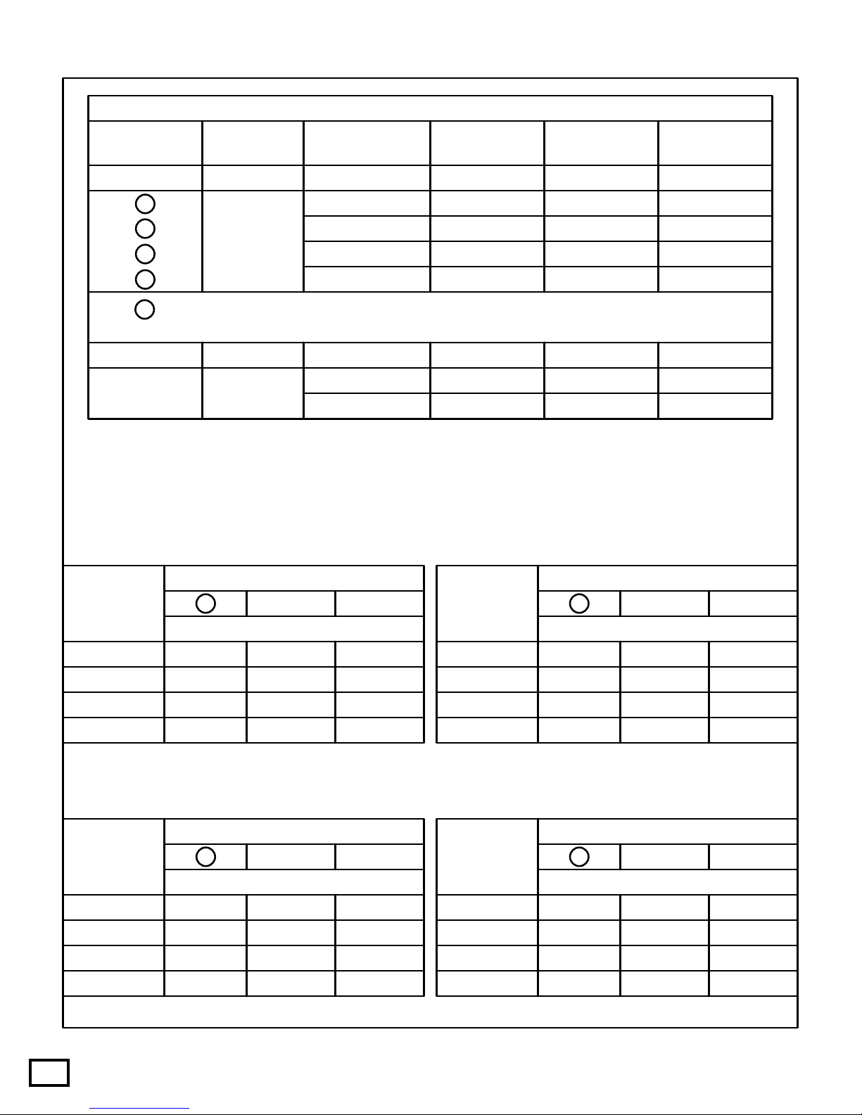
Figure 23
AUTOMATIC TRANSMISSION SERVICE GROUP
Technical ServiceInformation
20
Shift Solenoid Application Chart
Selector Lever
Range Commanded
Gear Shift
Solenoid "B"
Shift
Solenoid "A" TCC
Solenoid Coast Clutch
Solenoid
P/R/N 1
1
2
2MANUAL 2
MANUAL 1
MANUAL 1 2
1
3
4
ON
ON
ON
ON
ON
ON
ON
ON
ON
OFF
OFF
OFF
OFF
OFF OFF
OFF
OFF
OFF
OFF
D
D
D
D
D
Cancel First Through 3rd Gear Only, SSA, SSB, TCC, Same as Overdrive, CCS Always On.
* *
* *
* *
* *
*
***
*
*
Controlled by PCM
DSelector Lever Position
Actual Gear Obtained
PCM Gear
Commanded 2 1
1st
2nd
3rd
4th
SHIFT SOLENOID "A" ALWAYS OFF
4
4
3
32
2
2
2 2
2
2
1
DSelector Lever Position
Actual Gear Obtained
PCM Gear
Commanded 2 1
1st
2nd
3rd
4th
SHIFT SOLENOID "B" ALWAYS ON
2
2
2 2
2
2
2
2
3
3
1
1
DSelector Lever Position
Actual Gear Obtained
PCM Gear
Commanded 2 1
1st
2nd
3rd
4th
SHIFT SOLENOID "A" ALWAYS ON
2
2
2
2
2
2
1
1
1
1
1
1
DSelector Lever Position
Actual Gear Obtained
PCM Gear
Commanded 2 1
1st
2nd
3rd
4th
SHIFT SOLENOID "B" ALWAYS OFF
4
4
2
2
2
2 2
2
1 1
11
SHIFT SOLENOID TROUBLE CHART GUIDE
Table of contents
Other ATSG Microphone System manuals


