ATT Hammer Jet v1 User manual

Revision 1 - April 2020
Operating Manual
Hammer Jet v1 Dryer & Cleaner

2
EU Declaration of Conformity.......................................................................................... 3
Annex 1 to EU Declaration of Conformity............................................................................4
Nameplate................................................................................................................5
Safety Instructions....................................................................................................... 7
Obligations................................................................................................................7
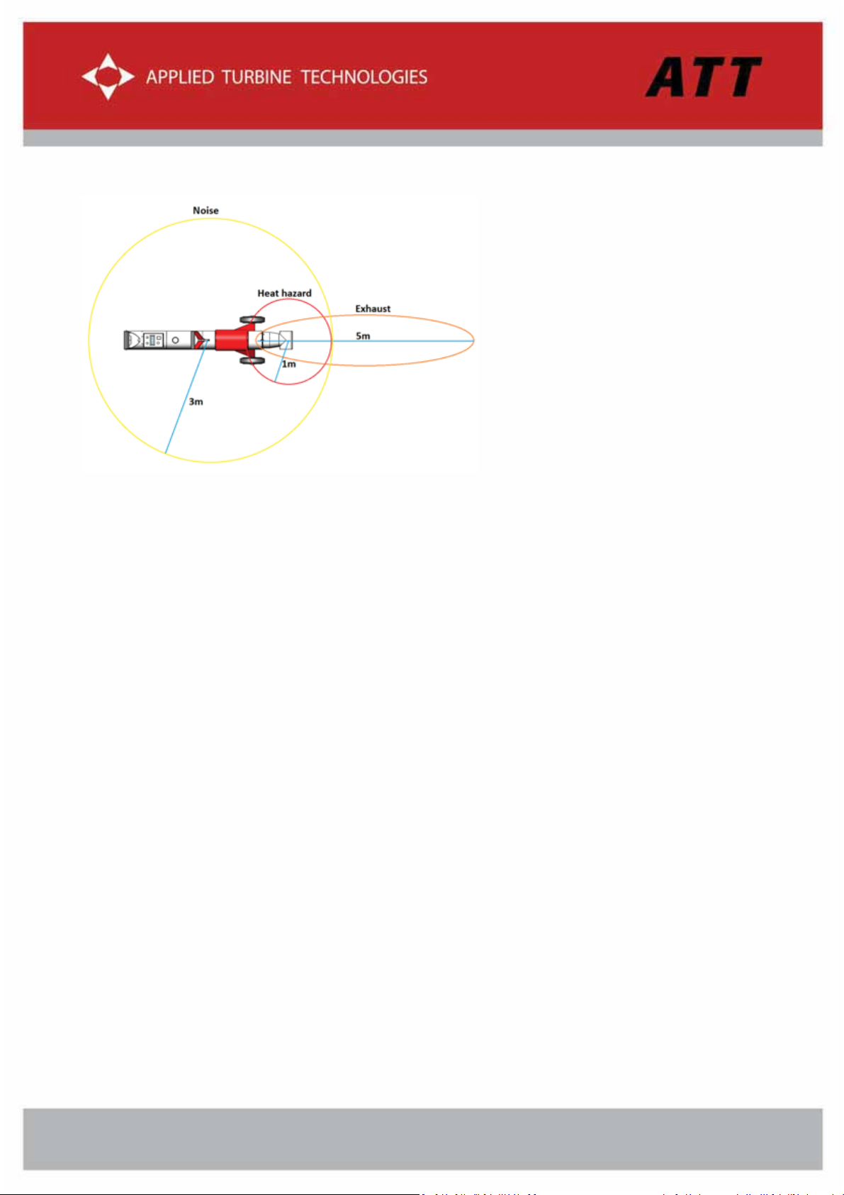
Hazard and danger zones...............................................................................................8
Intended use .............................................................................................................8
Misuse .....................................................................................................................9
Disclaimer ................................................................................................................10
Introduction..............................................................................................................10
Hammer Jet Dryer & Cleaner........................................................................................ 10
Product Overview.......................................................................................................11
Display “Operation Hours & Time to Service”..................................................................... 12
Display “Ready to Start”.............................................................................................. 12
Display “Idle” – Ready to use ........................................................................................ 13
Display “Low Power Setting” ........................................................................................ 13
Recommended elevation for optimal drying speed............................................................... 14
Display “High Power Setting”........................................................................................ 14
Accessories and Spares ............................................................................................... 15
Operation.................................................................................................................16
Safety Instructions..................................................................................................... 16
Before start-up......................................................................................................... 17
Safety Stop............................................................................................................. 18
Power-up and start-up................................................................................................ 19
Shut down and Cooling................................................................................................ 22
Parking, transport and storage ...................................................................................... 22
Dismantling the turbine module from the chassis ................................................................ 23
Installing the turbine module........................................................................................ 25
Charging the Hammer Jet ............................................................................................ 28
Filter Removal ......................................................................................................... 29
Cleaning the turbine compartment ................................................................................. 31
Display shut down ..................................................................................................... 32
Re-fuelling.............................................................................................................. 32
Filter inspection and change......................................................................................... 33
Technical Data...........................................................................................................34
Dimensions.............................................................................................................. 34
Warning Signs .......................................................................................................... 36
Troubleshooting.........................................................................................................37
Off conditions.......................................................................................................... 37
Maintenance and Service..............................................................................................38
Turbine module compartment....................................................................................... 38
Filter cover............................................................................................................. 38
Overview of recommended maintenance and service............................................................ 39
Wheel inspection and replacement ................................................................................. 39
Storage & Transportation..............................................................................................40
Wastedisposal............................................................................................................40

3
EU Declaration of Conformity
The undersigned, representing the following manufacturer:
Applied Turbine Technology ApS
Østager 2, 6400 Sønderborg, Denmark
hereby declares that:
Machine type no
.
10000-40-80
is in conformity with all relevant provisions of the following EC directive(s):
DIRECTIVE 2006/42/EC OF THE EUROPEAN PARLIAMENT AND OF THE COUNCIL of 17 May 2006
on machinery
The EMC Directive 2004/108/EC
Person authorized to collect technical data and make them available to the relevant authorities:
Name
Address
Mike Claudi Kühl
Østager 2, DK-6400 Sønderborg
The machine’s design has taken the standards and specifications referenced in Annex 1 of the EU
Declaration of Conformity into consideration.
Sønderborg, April 12, 2020
Brian Ellegaard Andersen
CEO

4
Annex 1 to EU Declaration of Conformity
References to standards and specifications used for the Declaration of Conformity:
Harmonized standards:
Number
Version
Title
DS/EN 60204-
2006
Safety of machinery – Electrical equipment of machines
– General requirements
DS/EN ISO 13849-1
2006
Safety of machinery – Safety-related parts of control
systems – General principles for design
ISO 12100
2011
Safety of machinery – General principles for design.
Risk assessment and risk reduction.
Other standards:
Number
Version
Title
Other specifications:
Number
Version
Title

5
Nameplate
The Hammer Jet is provided with a name plate according to the requirements stated in the Directive
2006/42/EC placed on the “End Blinder” plate next to the charging port.
The nameplate is showing the CE and EAC (Russia) symbol as well as the website of the manufacturing
company (for contact information etc).
The nameplate is also showing some important product information such as:
xTYPE: Model number of the product
xS/N: Serial number, a unique product number
xYear: Year of manufacturing
xLWA: Sound level in dB at less than 1m distance from the noise source.
The Hammer Jet has an A-weighed max sound power level of 108 dBA around the machine and 103 dBA at
the operators’ position, at its max performance. The LWA is here not directly related to an environmental
noise level as weighted average of the different work steps during machine operation. It is the maximum
sound pressure which the operator will experience when using the machine at 100% performance level.
This choice of LWA was made to ensure proper health protection even when the machine is used above its
intended use.
When persons are exposed to excessively loud
environments (85 dB or more), hearing protection
is required to prevent noise-induced hearing losses.
The table to the left is showing the acceptable
noise levels without hearing protection during a
maximum daily exposure.
It is required that the operator of the Hammer Jet is using relevant hearing protection to prevent work
induced hearing losses.

6
In the United States hearing protection is by law assigned a single number rating, NRR, which is an
abbreviation for a Noise Reduction Rating. Hearing protection is available with NRR ratings from 0 to 30.
The required NRR level of a hearing protection is an estimate of the exposed daily noise level dose, which
then can be converted to an 8-hour Time Weighed Average called TWA. The following table shows the
required NRR rating for the hearing protection dependent of the average machine usage a day.
TWA exposure Operator
Working hours 1 2 3 4
Work exposure dB(A) 103 103 103 103
(100% Machine performance level)
TWA dose dB(A) 89 93 96 98
NRR protection rating 15 23 29 33
dBA reduction (NRR-7)/2 4 8 11 13
Requirement dB(A) 85 85 85 85
In this table the LWA value is used in the calculation of the TWA dose as a “worst case”, although the
operator normally would operate the machine at lower performance level because the marking equipment
often is limiting the overall operation.
The highest NRR rating for earplugs is 33, and the highest available NRR rating for earmuffs is 31. These
values reflect the level of noise protection available for each device when worn alone. Combining earplugs
with earmuffs can offer an NRR protection level of 36.
The environmental exposure will depend on how the work is done. It is possible to work below an
environmental sound pressure LWA of 108, if that is needed, but it will require that the machine is
operated below 50% of the maximum possible.

7
Safety Instructions
Obligations
Obligations of the Operator/manager:
The Hammer Jet must only be operated by personnel with the following knowledge:
xAre aware of the basic workplace safety information and accident prevention regulations.
xHave been instructed and trained in working with the Hammer Jet.
xHave read and understood this operating manual.
The operator is obliged to as follows:
xTo ensure that the required service and maintenance is performed according to the instructions laid out
in this operating manual.
xTo keep all the warning pictograms on the machine in a legible state.
If you still have queries, please contact the representative or manufacturer.
Obligations of the Operator:
Before starting work, all operators are obliged to as follows:
xTo comply with the basic workplace safety instructions and accident prevention regulations.
xTo read and understand the operating section of the operating manual.
xTo use the required personal protective equipment, when working with the Hammer Jet.
xTo read the section "Warning symbols and other labels on the machine" in this operating manual, and to
follow the safety instructions represented by the warning symbols, when operating the machine.
xTo get the required work training.
If the operator discovers that a function is not working properly, he must eliminate the fault immediately. If
this is not the task of the operator or if he does not possess the appropriate technical knowledge, then he
must report this fault to his superior (supervisor).

8
Hazard and danger zones
The hazard and danger zones are illustrated in the above figure.
Each hazard zone requires its own protection measures:
xThe NOISE zone requires protection to avoid loss of hearing ability.
xThe EXHAUST zone, where the use of safety glasses are required.
xThe HEATING zone, where use of safety shoes are required.
Intended use
The Hammer Jet intended use is for outdoor drying and cleaning of roads, runways, concrete areas or other
areas of non-flammable surfaces.
The product is using the exhaust from a micro jet turbine to dry and clean the surfaces and should not be
used on surfaces covered with sand or gravel as well as waste of or close to flammable materials.
The product is intended to be operated by a professional construction worker according to the guidelines in
the instruction manual using the required PPE's.
When operating the Hammer Jet hearing protection is mandatory. In restricted work areas with limited
air exchange respiratory protection or a limited use can be necessary to apply.
A backup operator needs to be present, where oncoming traffic is not shielded from the working area or on
roads in short range visibility areas.

9
During turbine operation, always ensure that the outlet air from the nozzle opening freely can get out. Do
not cover and do not put the nozzle opening in such way that it the air flow is hindered.
Misuse
The product Hammer Jet should not be used indoor, since the jet turbine is using fuel and the exhaust
emission could be toxic.
As soon as the turbine engine is warming up or running the machine needs to be moved in order not to
leave unintended hot spot marks on the ground.
Bystanders should be kept behind the machine when working, or at a safety distance of 5m away from the
nozzle cover in the working direction. The exhaust can lead to ejection of debris such as dust, sand or small
gravel, which can lead to eye injuries.
Examples of intended use:
xDrying and cleaning prior to road marking
xDrying and cleaning prior to crack repair and joint sealing on roads, runways, aprons etc.
xDrying and cleaning prior to line and tape marking/removal
xDrying and cleaning prior to paving on concrete and asphalt.
This Operating Manual utilise the following safety signs. Follow these safety signs carefully since failure to
comply may cause personnel injuries or irreparable damage to the equipment.
WARNING
Personal injury / mortal danger
A usage situation of a technical nature or similar that may cause personal injury or
mortal danger.
CAUTION
Damage to machine or accessories
A usage situation of a technical nature or similar that may cause damage to the machine
or its accessories.

10
ATTENTION
Important information
A usage situation of a technical nature or similar that is very important.
INFORMATION
The product without operational disturbances. Provides useful tips and
recommendations as well as information about the efficient use.
Disclaimer
All specifications and instructions in this document conform to the rules and provisions in the EU
Machinery Directive 2006/42/EC and Directive 2004/104/EC.
INFORMATION
This Operating Manual is subject to change without prior notice.
Contact info@zirocco.dk to request new editions of the Guide.
The warranty will be voided if the product is damaged for one of the following reasons:
•Non-compliance with the instructions in this Operating Manual
•Use of the product for a purpose it is not designed for
•Natural wear or tear
•Incorrect installation performed by the owner or a third party
•Mechanical or technical alterations
•Use of unauthorized spare parts
•Non-compliance with the maintenance instructions or lack of maintenance within the prescribed service
intervals.
•Use of safety button.
Introduction
Hammer Jet Dryer & Cleaner
•A small and versatile jet turbine dryer, cleaner and heater. The lightweight and compact design makes it
easy to always have on site for many tasks within different industries. The Hammer Jet is easy to
operate and to deploy even on uneven surfaces.
•Independent and convenient machine operation as there is no need for a compressor or bottled gas
supply.
K
K

11
•The Hammer Jet is equipped with a gas turbine which operates on standard diesel type EN590 mixed
with 5% ATT turbine oil. The Hammer Jet does not use LPG, which makes its use possible also in
populated areas.
•Only hot air - no open flames (a requirement for operations many airports etc.)
•Drying and cleaning speed up to 2.5 km/h depending on the surface and weather conditions and nozzle
width.
Product Overview
Hammer Jet in the dedicated transport
box with the 15 cm standard nozzle
Handle w/two-step throttle
Filter holder for the turbine
inlet air
Display, start, stop & power
setting buttons
Refuelling point & fuel cap &
lifting handle
Filter holder, air filter & filter
cover

12
Display “Operation Hours & Time to
Service”
- This information appears app. 1 second after
activation of the display button with a duration of
app. 2 seconds.
1) Total Operating hours and minutes on the
installed turbine module
2) Next service time in hours and minutes for the
installed turbine module
Display “Ready to Start”
- This information appears app. 5 seconds after
activation of the display button.
1) Nozzle air temperature
2) Battery Voltage (Must be higher than 11.2V
before start-up)
3) Last off condition
4) RPM (x1000)
1
2
6
6
1
2
3
4
6
3
Figure 1
Figure 2 - Display

13
Display “Idle” – Ready to use
- This information appears app. 10-15 seconds after
activation of the start button.
1) Nozzle air temperature
2) Battery voltage (Must be higher than 11.2V
before start-up)
3) Power output
4) Throttle set point
Display “Low Power Setting”
1) Nozzle air temperature
2) Battery voltage (Must be higher than 11.2V
before start-up)
3) Power output
4) Throttle set point
1
2
3
4
6
1
2
3
4
6
Figure 3 - Display
Figure 4 - Display

14
Recommended elevation for optimal
drying speed
Figure 6 – Nozzle opening position for optimal drying speed.
Display “High Power Setting”
5) Nozzle air temperature
6) Battery voltage (Must be higher than 11.2V
before start-up)
7) Power output
8) Throttle set point
1) Keep the nozzle opening 1-2 cm above the
surface to get optimal drying speed.
Do not force the nozzle opening into the surface,
because this will stop the outlet of the air flow
from the nozzle opening and can cause damage
to the turbine.
2) For slower but wider drying width, then elevate
the nozzle opening few cm more
1
2
3
4
6
Figure 5 - Display

15
Accessories and Spares
Item
Description
Order no.
Battery Charger for Hammer Jet 90-
265V assembly (EU plug)
3A, 12.6V
12000-130
Battery Charger for Hammer Jet 90-
265V assembly (US plug)
3A, 12.6V
12000-135
Hammer Jet Air Filter (HS 84213100)
For replacement minimum
every 10 hours of operation
5000-65
Battery Pack for Hammer Jet
LI-PO 11,1 V, 4500 mA
4000-450
Fuel Cap
Fuel tank cap
5000-425
Labels: ATT
Logo
9000-30
Label: Heat
Warning sign
9000-20
Label: Hearing protection
Warning sign
9000-10
Turbine oil
ATT Turbine oil
7000-80
200 mm Wheel for Hammer Jet
Ø200 mm
5000-430
A50H v1 Hammer Jet Turbine
Module (HS 8411810090)
Turbine incl. Flange and
nozzle (must be complete
when returned for service)
12000-100
Hammer Jet v1 Chassis stand-alone
(HS 8411810090)
Hammer Jet v1 without the
turbine module
10000-40-80-1
Hammer Jet Main Transport Box
(dimensions: 1423x463x553 mm)
Protection box for daily use,
transport, storage, and
shipping
8000-40
Hammer Head Nozzle 15/20cm (HS
8419900000)
Standard nozzle (delivered
with the product) is 15 cm,
however on request wider
nozzles can be delivered
14010-10

16
Operation
Hammer Jet may only be operated by personnel, who have read and understood this Operating Manual.
Relevant product training could cover the following subjects:
•Operation of the Hammer Jet
•Fuel mix and refuelling procedures
•Maintenance procedures, hereunder air filter replacement
•Turbine module replacement
•Machine safety
•Transport and storage
Safety Instructions
WARNING
Fire hazard
Do not use the Hammer Jet indoors or close to flammable material.
Hot exhaust air/safety distance
The outlet temperature next to the turbine is 350 to 550˚C. Keep a distance of at least 5
m from the machine during operation.
Hearing and eye protection
The personnel in the immediate vicinity of the Hammer Jet must use hearing protection
and safety goggles, when operating the Hammer Jet.
CAUTION
Fuel
Use Exxsol D80 or Shellsol D70 petroleum/Kerosene along with 3 % ATT Turbine oil
(7000-80) in the mixing ratio 1 to 30. (20 litres of fuel to 0.6litreof ATT Turbine oil).
When utilizing US Gallons, the mixing ratio is 0.6 litre ATT Turbine Oil to 5 US Gallons of
Kerosene
Nozzle
Always check the nozzle for damages, cracks or constrictions before use.
Keep under supervision
Do not power up and leave the Hammer Jet unsupervised.
Do not transport the Hammer Jet before it has cooled down completely.
Transport and storage

17
Figure 7 - Starting position of the Hammer Jet
Do not transport or store the Hammer Jet before it has cooled down completely (nozzle
temperature must be below 50°C/122°F.
Only use the dedicated Hammer Jet Transport Box, when not in use, and for storing and
transportation the Hammer Jet. This will shelf the product against dents, dust and dirt.
Always keep the Hammer Jet Transport Box clean and tidy.
.
Before start-up
Figure 8 - Fuel mix and amount
1) Place the Hammer Jet in horizontal
position (to ensure proper fuel
supply).
2) Do not try to start in any other
angles, since this can cause excessive
fuel leakage, overheating and
malfunction, which may lead to
permanent damage.
1) Ensure correct fuel mix and sufficient fuel amount
to perform start-up and operation of the turbine.

18
1) Prior to start-up, ensure proper charging and
battery level of minimum 11.2V.
SSafetyy Stop
1) Press the “Stop” button (also used for reset during
cooling down) to turn off the Hammer Jet turbine
(will enable cooling down).
Figure 9 – Power level at start-up
Figure 10 - Safety stop

19
Power-up and start-up
Figure 12 – Step 2: Idle mode
1) Push the “1” on the “power” button to turn the display on.
1) Wait 5-10 seconds until the ECU has started and the display settles
with the shown information.
1) Push the “stop/reset” button to reset the display and enable start-up.
Figure 11 - step 1: Start up
Figure 14 - Step 3: reset the
ECU

20
1) Push the “Start” button to turn on the turbine.
Figure 16 - Step 5: Idle mode
1) Wait 5-10 seconds until the turbine is in idle mode with the shown
display indication.
Figure 16 - Step 6: Option “Low” or
“High” on the Power button
1) Choose between “High” or “Low” throttle on the “Throttle Mode
Switch” for activation of the relevant air flow for the task (the higher
throttle level, the higher fuel consumption). The two modes are
activated in combination with a soft press on the throttle
Figure 14 - Step 4: Start-up of the
turbine
Table of contents
Other ATT Washer Dryer manuals
Popular Washer Dryer manuals by other brands

Siemens
Siemens WK14D321GC Instruction manual and installation instructions

Frigidaire
Frigidaire FFLE1011MW0 Use & care guide

Whirlpool
Whirlpool Washer/Dryer Pedestal installation instructions

Beko
Beko HTV 8736 XSHTR user manual

Electrolux
Electrolux EWW 167580 W user manual

Bosch
Bosch WNA14400TH/02 User manual and installation instructions