ATTA Freedom Fill User manual

1
2018
Aluminum Tank & Tank Accessories, Inc.
2702-B N. Nichols, Fort Worth, TX 76106
800-773-3047 * 817-378-8455
www.ATTAtank.com
FREEDOM FILL AUXILIARY SYSTEM
Gauge & Switch Console
FILL OUT WARRANTY CARDS FIRST BEFORE
INSTALLATION. WARRANTY WILL BE VOID IF WE
DO NOT RECEIVE WARRANTY CARD.
NOTE: Visit our webpage at www.attatank.com, for a helpful instructional video of an installation.
Follow us on Facebook: www.facebook.com/aluminumtanks
SAFETY PRECATIONS:
*READ ENTIRE INSTALLATION INSTRUCTION PRIOR TO INSTALLATION.
*Use proper eye protection during any installation.
*Work in a well ventilated area.
*Do not connect or disconnect any wires with ignition in the on position
*Do not modify or substitute any component provided with installation kit.
*Any questions regarding installation, please contact your dealer.
*Warranty will be void if installation is not followed as per installation instructions.
2
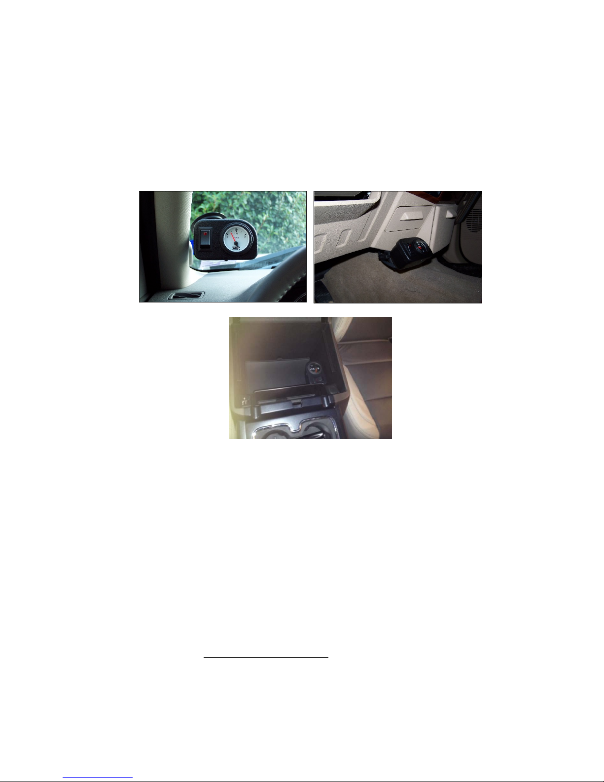
1. Mount the Gauge & Switch Console on desired location on dash. Note: Attach locking suction cup to
console arm to mount on windshield. Clean surface area to insure proper seal of suction cup. Or remove
suction cup to mount directly to dash. Run wires to the underside of the instrument cluster. Insure the
wires will not interfere with any moving parts (IE: brake pedals, parking brake, etc.). It may be
necessary to drill a hole for routing of wires. (NOTE: When routing wires, it is not necessary to pull
wires tight, give yourself some slack).
EXAMPLE OF MOUNTING POSITION OPTIONS SHOWN BELOW:
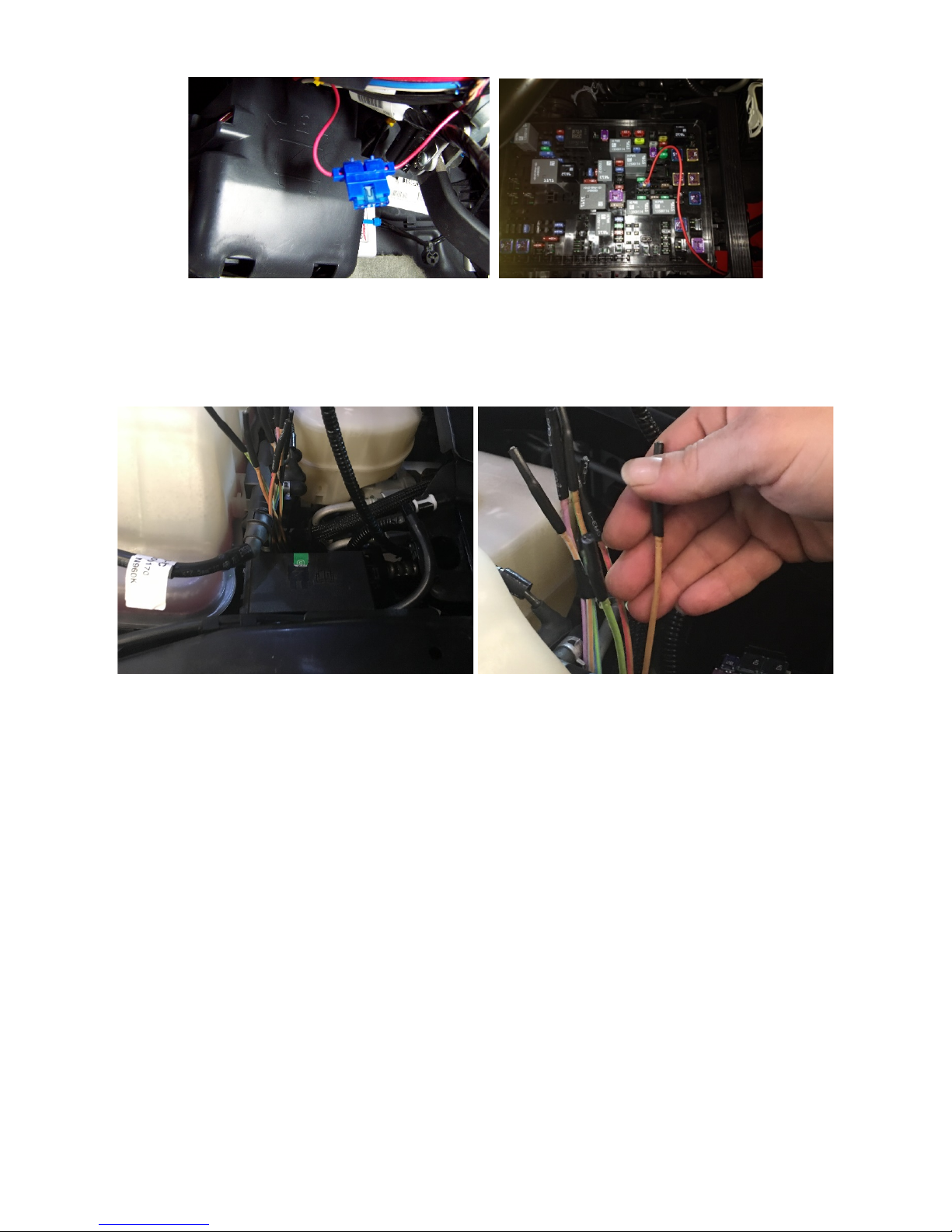
2. Place the Freedom Fill Controller Box under the instrument panel, (It may be necessary to remove the
dash panel). This can be done by using two zip-ties to attach the controller to a factory harness or
bracket. Insert the Controller harness to the Controller Box.
DO NOT PLUG IN COMPUTER MODULE WITH THE POWER ON, THIS MAY DAMAGE
THE COMPUTER MODULE!!
3. Connect the GREEN wire from the Gauge & Switch Console and Controller Harness to chassis ground.
This can be done by attaching a small eyelet to the wire and using a self-tapping screw to a chassis
ground.
4. See owner’s manual for location of either a spare fuse or upfitter fuse. Connect the RED wire off the
switch to a 12 volt ignition power source. When using a factory fuse, tap into the cold side of fuse. The
cold side is the side of the fuse with no power in the fuse panel when fuse is blown. Note: Spare,
Auxiliary, Upfitter or SEO (Special Equipment Option) fuses are not used in any factory system and
should be used when adding any accessory part. Do not connect red wire to direct battery power. To
add the 15 amp inline fuse to the red wire, cut the red wire and place one end of the wire inside the fuse
holder and clamp that side down. Place the other side of the wire to the other side of the fuse holder and
clamp down. Insure each side of the fuse holder is properly in the locked position. Insert the 15 amp
fuse to the fuse holder at the end of the installation.
3
Examples of 12 volt ignition power sources. (Examples only, due to variations in vehicles, see owner’s
manual.)
2017 Ford – w/ upfitter switches = Brown wire near under hood driver side fuse panel. (To locate wire, reach
down behind the under fuse panel. You should be able to feel a group of blocked of wires. Pull the wires up and
find the solid brown wire).
2017 Ford – w/out Upfitter Switches, #35 (Under Hood fuse panel – Passenger Side)
2015 Chevrolet 2500HD = #30 fuse, SEO, 15 amp (Located on Driver Side Fuse Panel)
2014 Ford F350= #44 Fuse, Auxiliary (Located on the Passenger Side Fuse Panel)
2014 GMC Denali 2500HD= #51 fuse, SEO/ALC (SEO Upfitter Usage)
2011+ Dodge = Fuse #93 – (Located under hood driver’s side)
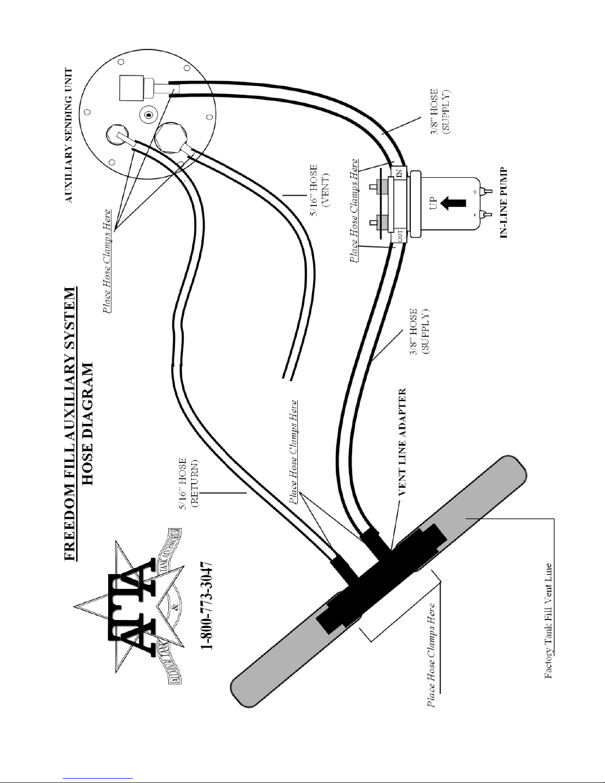
5. Connect the BROWN wire from the Gauge & Switch Console to the BROWN wire on the controller
harness. Connect the PURPLE wire from the Gauge & Switch Console to the PURPLE on the
Controller Harness. Using the supplied POSI-Tap, splice the YELLOW wire from the FTC computer
module harness to the YELLOW wire from the fuel gauge (NOTE: The yellow wire from the fuel gauge
will be routed through the factory fire wall (Step 7).
6. Connect the ORANGE wire from the Gauge & Switch Console to the Factory dimmer switch wire.
This wire is used for the auxiliary gauge light. The wire can be found behind the factory dimmer switch.
It may be necessary to use a test light to determine the proper wire. (See owner’s manual)(Use the
supplied splice to tie the orange wire to the factory dimmer switch wire).
Example Dimmer Switch Wire Colors:
11-14 GM/Chevrolet – Brown with White Stripe
GM+ = Yellow
Dodge – Orange with Grey Stripe
Ford- Purple with Gray Stripe

4
7. Route the remaining wires (White, Black, Blue, and Yellow “from fuel gauge”) through the fire wall and
route the wires along the frame rail. Insure the wires do not come in contact with any moving parts. Use
a small grommet or use a rubber boot when routing wires through firewall to insure wires will not chaff
and create a short.
8. Apply a gasket sealer to both sides of the gasket of the Sending unit. Install the Sending Unit Assembly
to the tank using self-tapping screws. DO NOT BEND FLOAT ARM WHEN INSTALLING
SENDING UNIT INTO THE TANK. Attach the Sending unit harness to the tank. The Yellow wire
attaches to the center brass post of the Sending unit. The Green wire attaches under any of the self-
tapping screws.
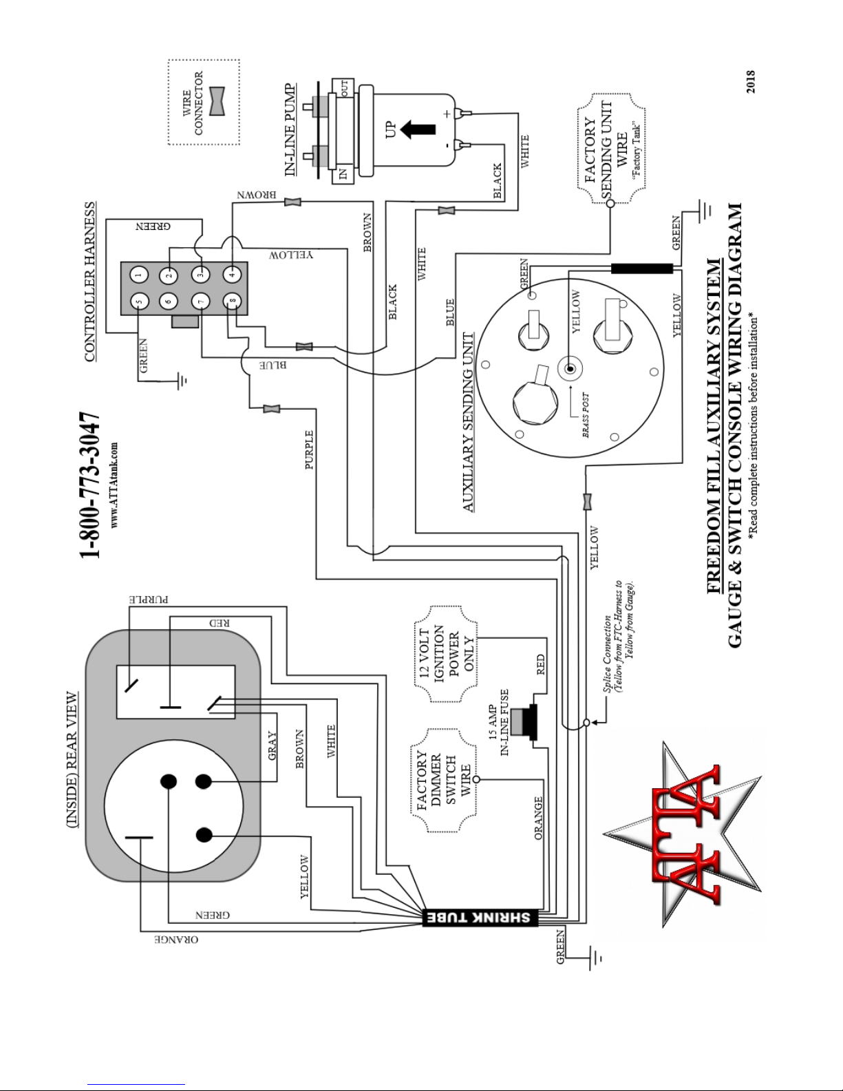
9. Connect the 3/8” hose to the 3/8” supply port/check valve on the Sending Unit using a hose clamp.
Connect the long 5/16” hose to the 5/16” black nylon return port using a hose clamp. Connect the short
5/16” hose to the 5/16” aluminum vent port using a hose clamp. Inspect all hose clamps to insure proper
seal.
10. Remove the lock-bar from the auxiliary tank and throw away shipping screws. Center lock-bar in bed
and drill a 3/8” hole approximately 1” from each end of the lock-bar through the lock-bar and truck bed,
then place a 3/8” carriage bolt in each hole. Insure the auxiliary tank is placed on some sort of isolation
mat. (Drop-In or Spray-In bed liners will work. Mud Flaps or a rubber mat will work also). Position and
center the auxiliary tank in the truck bed. The front hold-down tabs of the tanks will slide under the
lock-bar. Drill a 3/8” hole in the rear hold-down(s) of the tank and bed, and then place a bolt in the hole.
Route the wires and hoses under the truck. Insure the hoses are properly tied and no sharp bend was
created. Place one flat washer, one lock washer and one nut on each bolt. Tighten all bolts.
11. (A) ONLY TRUCKS WITH INTERNAL FILL VENT LINES NEED TO FOLLOW THIS STEP,
ALL OTHERS SKIP TO 11 B. Trucks with an internal fill vent line it will be necessary to use the
push-in adapters (not included with kit) on the factory fill neck in place of the vent-line adapter.
Disconnect the factory fill from the body of the truck. Pull the assembly down the underside of the truck
to make it easier to work on and prevent metal shaving to fall into factory tank. Using a 19/32” drill bit
(a 9/16” bit may used, only if the 19/32” cannot be found), drill two (2) holes into the metal portion of
the factory fill neck. *Note: Insure that the holes will be on the side of the factory fill neck facing the
engine side of the truck when it is bolted back to the factory position. Remove any shaving that may
have been produced. Place a bead of gasket sealer around the ring of the rubber boot of the adaptor, (do
not install the elbow at this time). Insert the rubber boot into the 19/32” hole of the factory fill neck.
Insert the metal elbow into the rubber boot. Insure that it has a snug fit. Place one long cable-tie around
each of the push-in adapters.
NOTE: In some later year GM/Chevrolet vehicles, you may be required to pull excess factory vent hose
and remove excessive slack before installing Vent-Line Adapter.
11. (B) Locate the factory fill neck on the inboard side of the truck bed. The vent line adapter has both a
5/8” & ¾” step, the same vent line adapter will be used for both sizes. (If it is a 5/8” vent line, place it upon
the 5/8” portion (lower step) of the Vent-Line Adapter. If it is a 3/4" vent line, place it upon the 3/4" portion
(upper step) of the Vent-Line Adapter.) Mark the factory vent line where the cut should be made, insuring
that you will have enough factory vent hose to slide over the adapter. Cut a small section (approx. 1” or
more) out of either the 5/8” or 3/4” factory vent line. Place a large hose clamp on each side of the cut
section. Insert the vent-line adapter and tighten the #12/#10 hose clamps. NOTE: On some trucks with metal
fill vent lines, it will be necessary to cut a portion of the metal tube and add the applicable rubber hose to
install the Vent Line Adapter. Do not “kink” the vent hose. It does not matter whether the 3/8” fitting or the
5/16” fitting face the factory tank.

5
*Note: Vent Line Adaptor may differ than picture shown.
(Pictures below shows Factory Fill Neck removed from truck. Example Only. The Factory Fill Neck does not need to be
removed for installation of the Vent Line Adapter.)
((Installer Tip: When cutting a metal fill vent line, place a magnet on the line to catch any metal
shavings.))
**Warning: When mounting the Vent Line Adaptor, be sure that the position of the factory fill vent line, does
not allow the line to retain fuel. For example, a low portion of the hose that will hold fuel and not allow air to
escape when normally filling the factory tank. This will cause spit-backs for the station fuel nozzle. Any fuel in
the line needs to drain to the factory tank.
12. Mount the inline pump near the Vent-Line Adapter. NOTE: Mount the pump so the lowest portion of the
pump will be above the bottom of the frame rail. Insure the fuel flow is going from the auxiliary tank
(marked “IN” on pump) to the factory tank (marked “OUT” on pump). NOTE: Pump must be mounted
in upward position, arrow must be up. Run the 3/8” supply hose & the 5/16” return hose to the Vent-
Line Adapter Area. Attach the 3/8” supply hose to the inline pump. Place and tighten with a hose clamp.
It will be necessary to cut the excess hose off. Attach the remaining portion of the 3/8” hose to the other
side of the pump. Place and tighten with a hose clamp. Route the 3/8” hose to the Vent-Line Adapter
and place upon the 3/8” port. Route the 5/16” hose to the Vent Line Adapter. Place and tighten with a
hose clamp. ENSURE ALL HOSES ARE NOT KINKED OR BENT TO RESTRICT FUEL FLOW.
Note: when installing the Vent Line Adapter to the factory fill vent line, ensure the vent line will not
create a low spot where fuel will sit. This can cause fueling problems, when filling the factory tank.
NOTE: Place Vent-Line Adapter in the Up-Right position as shown in example photos.
13. The WHITE wire that was run through the fire wall will connect to the positive (+) wire on the pump.
The BLACK wire will connect to the negative (-) wire on the pump. (Note: Do not cross wires, or
damage to the FTC controller will occur. Damage to FTC controller will not be covered by warranty.)
Note: The negative wire of the Pump does NOT go to Chassis Ground.

6
14. The BLUE wire will splice into the Factory Sending Unit Wire. To ensure proper reading, attach the
blue wire as close to the top of the factory sending unit as possible. (Going from the inboard side of the
factory tank, it is possible to feel the factory wiring harness. Pull the factory harness towards you to
attach the BLUE wire to the factory sending unit wire).
Purple-04-14 GM/Chevrolet
Blue w/ Purple Strip 2015+ Gm/Chevrolet
Yellow with purple stripe-2008-current Ford (May have multiple same color wire in harness. Correct wire will have voltage –
Incorrect wire will have no voltage)
Yellow with white stripe 88 to 07 Ford front tank
Blue with black stripe 03 to 05 Dodge
Blue with white stripe-98-02 & 06-Current Dodge (May have multiple same color wire in harness. Incorrect wire will be
wrapped around another wire)
(See owner’s manual due to variations of truck wiring).
15. The long YELLOW wire from the gauge & switch will connect to the YELLOW wire from the
Auxiliary Tank. The GREEN wire from the auxiliary tank needs to be connected to chassis ground.
How the System Works
When the system is turned on, the Freedom Fill Controller box will sense when the factory tank is
approximately at a half a tank, the controller box will then turn the auxiliary in-line pump on, filling the
factory tank to approximately three-quarters of a tank. The light on the switch will turn on allowing you to
know when the system is transferring fuel. When the factory tank reaches approximately three-quarters of a
tank, the pump will then turn off. When the auxiliary tank is empty, the system will not turn on. If the
factory tank goes below approximate one-half of a tank, you know the auxiliary tank is empty. When the
switch is in the off position, the auxiliary gauge and computer will be off, and will not transfer fuel from the
auxiliary tank to the factory tank.
When the truck or the system first turns on, the pump &light will turn on for approx 5 seconds, then turn
off. If the factory tank needs fuel it will then turn back on and begin to transfer fuel. If the factory tank is
above approx ½ a tank, the system will remain off until the factory tank reaches the appropriate level of
approx ½ a tank. If the truck or Freedom Fill System is shut off during fuel transfer, it will not turn back on
until the factory tank reaches approx half a tank.
Please visit our website at www.attatank.com for latest updates and warranty information.
Need trouble shooting tips, please visit: http://www.attatank.com/freedom-fill-troubleshoot/
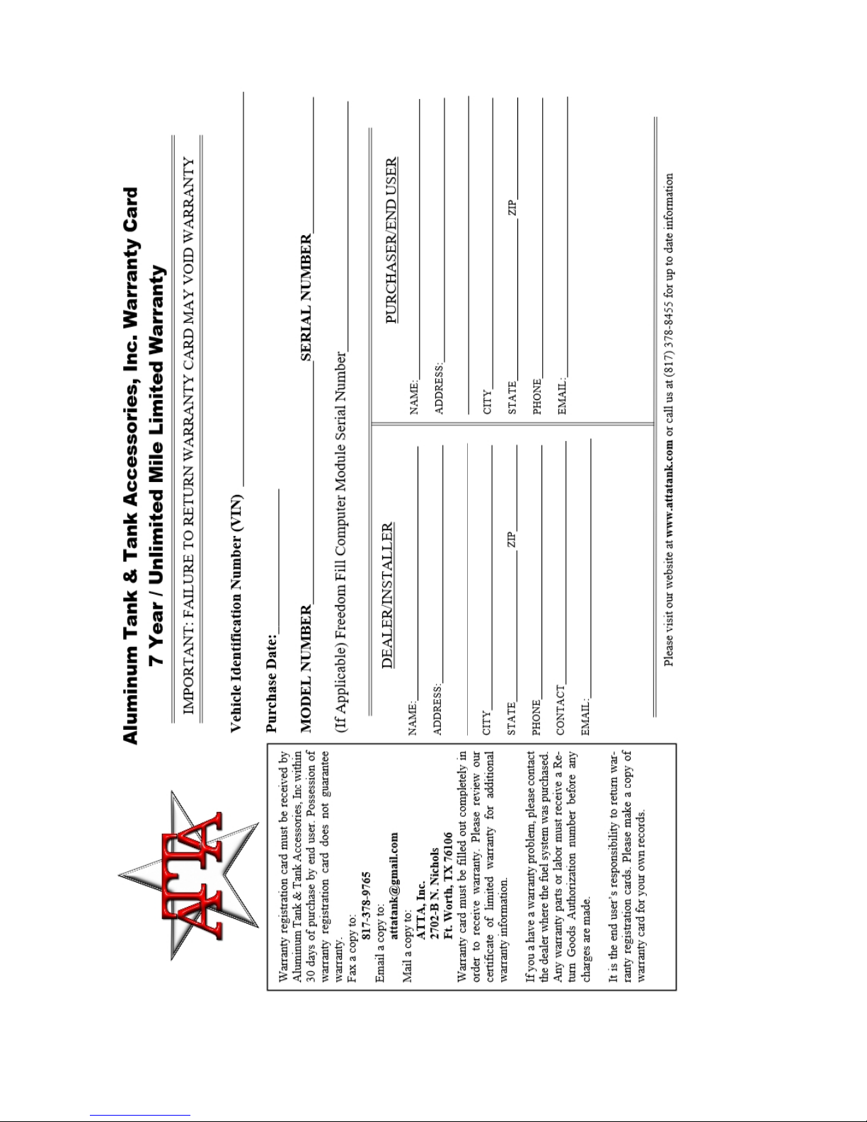
Return warranty card within thirty (30) days of installation to activate your
warranty.
7
8

9
Certificate of Limited Warranty
Effective Date: September 1, 2017
Warranty valid for any fuel tank, fuel system or headache rack purchased from Aluminum Tank & Tank Accessories, Inc (ATTA) on or after above
effective date.
Warranty is only valid with the return of warranty card to Aluminum Tank & Tank Accessories, Inc. within 30 days from the date of purchase by the
original purchaser. The 7 year/unlimited mile warranty will not be valid without the return of the warranty card. The limited warranty is valid only for the
vehicle listed on the warranty card. Valid only in the United States and Canada.
Seven Year/Unlimited Mile Warranty
Aluminum Auxiliary Fuel Tank Warranty:
Aluminum Tank & Tank Accessories Inc. (ATTA, Inc.) auxiliary diesel fuel tanks are covered by a 7 year/unlimited mile limited liability warranty, against
defects in material and workmanship. Aluminum Tank & Tank Accessories, Inc. fuel system components are covered by a 7 year/ Unlimited mile
limited warranty, except for the inline fuel pump and sending unit resistor. The inline fuel pump and sending unit resistor are covered by a 1 year limited
warranty per manufacture requirements. ATTA generator tanks and other manufactured products are covered by a 7 year limited warranty.
Aluminum Special Permit Transfer Tank Warranty:
Aluminum Tank & Tank Accessories Inc. (ATTA, Inc.) Aluminum transfer tanks with Special Permit (DOT-SP 20416) are covered by a 7 year/unlimited
mile limited liability warranty against defects in material and workmanship. The Special Permit is valid for 2.5 years from the date of manufacturing.
Refueling tanks must be retested every 2.5 years in accordance with 49 CFR 180.352. The end user is responsible to keep refueling tank within 49 CFR
180.352. Special Permit is valid for with diesel, ethanol, gasoline, methanol, kerosene and aviation fuel only. In order to maintain ATTA manufacture
warranty, the refueling tank must be maintained within accordance of 49 CFR 180.352 regulation. Failure to have refueling tank retested every 2.5 years
will void warranty. Failure to send ATTA, Inc retesting documentation within the 2.5 year limit will void ATTA, Inc manufacture warranty. Special Permit
must be carried aboard vehicle at all times. Refueling pumps and refueling pump accessories are covered via manufacturer warranty.
Aluminum Headache Rack Warranty:
Aluminum Tank & Tank Accessories Inc. (ATTA, Inc.) aluminum contour headache racks are covered by a 7 year/unlimited mile limited liability warranty,
against defects in material and workmanship. The 6” oval LED lights are covered by a 1 year manufacture warranty. Aluminum headache racks are not
intended as a safety device.
Powdercoat/Spray-On Bedliner/Vehicle Paint Warranty:
Powdercoat, Spray-on Bedliner, and Vehicle Paint finish are covered by a 1 year limited warranty against defects.
Aluminum Tank & Tank Accessories, Inc. warranty begins when the original purchaser purchases the unit. The original purchaser is the person who will
use for his own use. If a fuel tank or headache rack needs to be repaired, it shall be done at a “Repair and Return” only, unless deemed un-repairable by
ATTA, Inc discretion. If a part must be replaced, ATTA, Inc. will furnish the replacement part on a “Return and Replace basis” only. ATTA will pay the
established warranty labor rates, listed below, once authorization has been established. ATTA will make no payment for parts purchased or repaired in
the field without prior written authorization from ATTA. We will not accept any charges greater than our established warranty rates. We reserve the right
to examine the tank or part being claimed for warranty upon return to ATTA, with all shipping charges being prepaid to ATTA. If the warranty claim is
determined valid, repair or replacement will be made at ATTA discretion. Warranty will not be honored if the tank or the component failure is caused by
conditions beyond the control of ATTA such as damage caused by but not limited to:
1. Customer’s misuse or negligence.
2. Improper installation by the installer.
3. Shipment or improper handling.
4. Ordering of incorrect product
5. Use of Contaminated fuels or improper fuel additives.
6. Road Debris
7. Damage caused by fuel additives or contaminated fuels
Warranty claims will be valid only if completed warranty card has been received prior to claim by Aluminum Tank & Tank Accessories, Inc. Warranty will
not be honored if the product or system is altered in any way or if the ATTA manufacturing tag is removed or defaced. Warranty does not cover
consequential damages including, but not limited to: loss of use of the warranted product, loss of time, transportation expenses, towing, expenses for
travel, lodging, telephone, or fuel charges, loss of damage to personal property or loss of revenue. Warranty cards must be received within 30 days of
purchase by end user. It is the end user’s responsibility to fill out and send in warranty cards to Aluminum Tank & Tank Accessories, Inc.
Warranty Labor Rate @ $100.00/hr (subject to change without notice)
*Sending unit replacement in an easy to access ATTA tank (in-bed, Etc.) –1/2 hr
*Any procedure requiring removal and replacement of a fuel tank- 1hr
*Removal and replacement of inline fuel pump -1/2 hr
*Removal and replacement of Freedom Fill Controller box -1/4 hr
Troubleshooting and diagnostics fees will only be paid when Aluminum Tank & Tank Accessories, Inc. is contacted before troubleshooting begins. ATTA
will pay no labor rates without a written quote. Labor rates are only authorized with written approval from Aluminum Tank & Tank Accessories, Inc
before labor begins.
Warranty does not include the removal of non-ATTA products.
Please visit our website for current Warranty Claim Procedure
Aluminum Tank & Tank Accessories, Inc. 2702-B N. Nichols St. Fort Worth, TX 76106
10
Other manuals for Freedom Fill
1
Table of contents
Other ATTA Automobile Accessories manuals

Popular Automobile Accessories manuals by other brands


Axxess
Axxess OESWC-8113-RF installation instructions

AMP Research
AMP Research BedStep 75316-01A quick start guide

TAUBENREUTHER
TAUBENREUTHER 50-TG500-0 manual

Westfalia
Westfalia monoflex 350046600001 Installation and operating instructions

APS
APS IA06SJA1B installation instructions

Champion
Champion 94521CH user manual