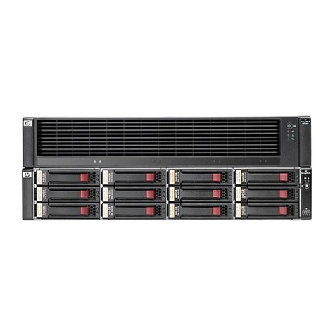
ATTO Technology Diamond Storage Array V-Class User manual

Diamond Storage Array
V-Class
Installation and Operation Manual
© 2005 ATTO Technology Inc. All rights reserved. All brand or product names are trademarks of their
respective holders. No part of this manual may be reproduced in any form or by any means without the
express written permission of ATTO Technology Inc.
2/05
6.4 PRMA-0338-000

ATTO Technology Inc.
Contents
Preface
1.0 Product Overview ...........................................................................1
Features
Fibre Channel model
SCSI model
2.0 Technical Overview ........................................................................3
ATA disk drives
ADXT Powers ATA to New Levels
3.0 Installation Instructions .................................................................5
Three major steps are required to set up the Diamond Storage Array
Step 1: physical setup
Step 2a: set up the Ethernet connection
Step 2b: connect to Ethernet
If the Diamond Storage Array is attached to a DHCP server
If the Diamond Storage Array is not attached to a DHCP server and you wish to change the
defaults
Step 3: configure drives
3.1 Components .........................................................................7
Floor model
Rack mount
3.2 Physical Setup ......................................................................9
Floor Model
Rack Mount
General Instructions
3.2.1 Connecting a Fibre Channel Array .............................11
Autoconfiguration
Manual configuration
3.2.2 Connecting a SCSI Array ............................................13
To connect the SCSI Diamond Storage Array
3.3 Determining Drive and Sled Designations .........................15
Numbering conventions
Physical numbering
Logical Numbering
Examples
Unique serial number for each LUN

Diamond Storage Array Installation and Operation Manual
4.0 Accessing the Array .......................................................................17
Command Line Interface
ATTO ExpressNAV
In-band SCSI over Fibre Channel
RS-232 port
Ethernet port
SNMP
4.1 In-band CLI Over Fibre Channel .........................................19
I/O details
4.2 Serial Port Access ................................................................21
4.3 Ethernet Access: Telnet and SNMP Protocols ..................23
To connect to the Ethernet port
To use Telnet
To use SNMP
4.4 ATTO ExpressNAV: Browser-based Interface ...................25
Browser Compatibility
To optimize ExpressNAV in Internet Explorer
To open an ExpressNAV session
To navigate ExpressNAV
4.4.1 ExpressNAV Pages ......................................................27
Status
Ethernet
SNMP
Serial Port
Fibre Channel
Storage Management
RAID
Clear Data
Logical Units
Partitions
Zoning
Rebuild
Configuration
Advanced
To use the Advanced Page CLI commands
Restart
Help
4.5 CLI: Interface via ASCII-based Commands .......................29
4.5.1 Summary of CLI Commands .......................................31

ATTO Technology Inc.
4.5.2 General Use Commands .............................................34
FirmwareRestart
Help
PartitionCommit
SaveConfiguration
SystemSN
VerboseMode
ZoneCommit
4.5.3 Fibre Channel Configuration Commands ..................35
FcConnMode
FcDataRate
FcFairArb
FcFrameLength
FcFullDuplex
FcHard
FcHardAddress
FcPortInfo
FcPortList
FcSCSIBusyStatus
FcWWName
4.5.4 Serial Port Configuration Commands ........................37
SerialPortBaudRate
SerialPortEcho
SerialPortHandshake
SerialPortStopBits
4.5.5 Ethernet Commands ....................................................39
EthernetSpeed
FTPPassword
IPAddress
IPDHCP
IPGateway
IPSubnetMask
SNMPTrapAddress
SNMPTraps
SNMPUpdates
Te l ne t Pa s sw o r d
TelnetTimeout
TelnetUsername
4.5.6 Diagnostic Commands ................................................41
AudibleAlarm
DiamondModel
DiamondName
DriveCopyStatus
DriveInfo
FcNodeName
FcPortList
FcPortName
Help
IdentifyDiamond
Info
LUNInfo
PartitionInfo

Diamond Storage Array Installation and Operation Manual
RAID5ClearDataStatus
RAIDRebuildStatus
SerialNumber
SledFaultLED
SMARTData
Temperature
VirtualDriveInfo
ZoneInfo
4.5.7 Drive Configuration Commands .................................43
ATA D i s k S t a te
AutoRebuild
ClearDiskReservedAreaData
DriveCopy
DriveCopyHalt
DriveCopyResume
DriveCopyStatus
DriveInfo
DriveSledPower
DriveWipe
IdeTransferRate
LUNInfo
LUNState
PartitionCommit
PartitionInfo
PartitionMerge
PartitionSplit
QuickRAID0
QuickRAID1
QuickRAID5
QuickRAID10
RAID5ClearData
RAID5ClearDataStatus
RAIDInterleave
RAIDHaltRebuild
RAIDManualRebuild
RAIDRebuildState
RAIDRebuildStatus
RAIDResumeRebuild
RebuildPriority
ResolveLUNConflicts
RestoreModePages
SledFaultLED
VirtualDriveInfo
ZoneAddDevice
ZoneAddHost
ZoneAddPort
ZoneClearAll
ZoneCommit
ZoneCreate
ZoneDelete
ZoneInfo
ZoneRemoveDevice
ZoneRemoveHost
ZoneRemovePort
ZoneRetrieve
ZoneState

ATTO Technology Inc.
4.5.8 Maintenance Services Commands .............................48
FcScsiBusyStatus
FirmwareRestart
MaxEnclTempAlrm
MinEnclTempAlrm
Temperature
Zmodem
ZoneRetrieve
5.0 Configuring Drives ..........................................................................49
JBOD (Just a Bunch of Disks)
RAID Level 0
RAID Level 1
RAID Level 10
RAID Level 5
Interleave
Partitions
Zones
Hot Spare sleds
Enhancing performance
5.1 JBOD .....................................................................................51
To set up the JBOD configuration
5.2 RAID Level 0 .........................................................................52
Sled-based versus disk-based
To set up RAID Level 0 groups
To remove RAID Level 0 groups from the array
5.3 RAID Level 1 .........................................................................55
To set up RAID Level 1 groups
To set up RAID Level 1 with Hot Spare sleds
To remove RAID groups
5.4 RAID Level 5 .........................................................................57
Configuring a fully-populated array
To set up one RAID Level 5 group with one Hot Spare sled
To set up two RAID Level 5 groups with two Hot Spare sleds
Configuring a partially-populated array
To set up one RAID Level 5 group with one Hot Spare sled
Removing RAID groups
5.5 RAID Level 10 .......................................................................61
To set up RAID Level 10 groups
To remove RAID groups
To set up RAID Level 10 with Hot Spare sleds:
5.6 Rebuilding RAID Level Configurations ..............................63
To reset LUN status
To synchronize mirrored drives automatically
Rebuild priority
To synchronize mirrored drives manually

Diamond Storage Array Installation and Operation Manual
5.7 RAID Interleave .....................................................................65
To change the RAID Interleave parameter
5.8 Creating Partitions ...............................................................67
To create a partition
To merge partitions
5.9 Creating Zones .....................................................................69
Principles of Zoning
Factors to consider
Status and Sense Data
Configuring Zones
To create a zone
To remove zones
To change current zones
Other operations
Errors
6.0 Copying Drives ................................................................................73
7.0 Updating Firmware .........................................................................75
Updating firmware via the RS-232 serial port
Updating firmware via the optional Ethernet card
8.0 System Monitoring and Reporting ................................................77
8.1 Troubleshooting ...................................................................81
Windows 2000 special instructions
Error Messages
System Fault LED
Command Line Interface messages
ERROR. Wrong/Missing Parameters
ERROR. Invalid Command. Type ‘help’ for command list
ERROR. Command Not Processed.
Audible Alarm
Specific situations and suggestions
If a drive fails to respond
If a power supply fails
To determine if the problem exists with the Host Interface Card or the connection
If you can’t access the array CLI via Ethernet
If you do not see the appropriate number of LUNs on the host machine
8.2 Resetting Defaults ................................................................83
Default
Return to Default settings
Factory Default
To reset to Factory Defaults, firmware version 2.5.3 or higher
9.0 Hardware Maintenance ...................................................................85

ATTO Technology Inc.
9.1 Hot Swap Operating Instructions .......................................87
Disk Drives
The following method is the safest way to perform a hot swap of a drive
Power Supplies
Blower Assemblies
To replace a blower assembly
9.2 Optional Hot Spare Sled ......................................................89
To set up RAID Level 1 with Hot Spare sleds
To set up RAID Level 10 with Hot Spare sleds
To set up one RAID Level 5 group with one Hot Spare sled
To set up two RAID Level 5 groups with Hot Spare sleds
Glossary .................................................................................................i
Fibre Channel technology
SAN technology
SCSI protocol
Appendix A ATA Disk Technology .......................................................iii
Appendix B Information command returns .........................................iv
Driveinfo
LUNInfo
PartitionInfo
ZoneInfo
Appendix C Sample Zoning Command Sequences ............................x
First time configuration (after download)
Simple
Symmetric Model
Asymmetric Model
Combined Symmetric/Asymmetric Model
Appendix D Product Safety ...................................................................xiii
Safety compliances
EMC specifications
Radio and television interference
Appendix E Specifications ....................................................................xiv
Environmental and physical
Rack mount dimensions
Floor mount dimensions
Appendix F Part numbers .....................................................................xv
Appendix G Warranty ............................................................................xvi
Manufacturer limited warranty
Contact ATTO Technology, Inc.

Diamond Storage Array Installation and Operation Manual

ATTO Technology Inc.
Preface
This guide will take the technology-savvy user through the installation and maintenance of the Diamond Storage
Array.
The Diamond Storage Array was designed to meet your need for large amounts of easily accessible storage using
proprietary Aggregated Data Transfer Technology (ADXT
J
) to merge the power of multiple, high performance
ATA disk drives with the sustained data transfer rates required by sophisticated computer users.
Your comments help us improve and update our products. Contact us:
ATTO Technology, Inc.
155 CrossPoint Parkway
Amherst, New York 14068
(716) 691-1999 • voice
(716) 691-9353 • fax
http://www.attotech.com/diamond
ATTO Technology can also be reached via e-mail at the following addresses:
Sales Support: sls@attotech.com
Technical Support: techsupp@attotech.com
Disclaimer
Although reasonable efforts have been made to assure the accuracy of the information contained herein, this
publication could include technical inaccuracies or typographical errors. Manufacturer expressly disclaims
liability for any error in this information and for damages, whether direct, indirect, special, exemplary,
consequential or otherwise, that may result from such error including but not limited to loss of profits resulting
from the use or misuse of the manual or information contained therein (even if Manufacturer has been advised of
the possibility of such damages). Any questions or comments regarding this document or its contents should be
addressed to Manufacturer.
Manufacturer provides this publication as is, without warranty of any kind, either express or implied, including,
but not limited to, the implied warranties for merchantability or fitness for a particular purpose.
Information in this publication is subject to change without notice and does not represent a commitment on the
part of Manufacturer. Changes may be made periodically to the information herein; these changes will be
incorporated in new editions of the publication. Manufacturer reserves the right to make improvements and/or
changes at any time in product(s) and/or program(s) described in this publication.
Diamond Storage Array Installation and Operation Manual

1
ATTO Technology Inc.
1.0 Product Overview
The Diamond Storage Array offers up to 24 ATA disk drives in a rack mount or floor model configuration.
The Diamond Storage Array is ideally suited for data
intensive applications such as web hosting, e-mail
servers, on-line transaction processing, digital video
editing, medical imaging and digital audio editing.
Virtually any high performance computing system
with a growing need for storage capacity can use the
power of the array.
With the cost effective approach of using ATA disk
drives, you can add more storage capacity as your
needs grow without the costs of other disk storage
technologies. You can also improve the performance
and capacity of the array cabinet as technology
progresses by simply replacing disk drive sleds and
host interface cards.
The array is operating system independent and
supports all popular computer hardware platforms and
network environments.
Three interface options are available: a 1-gigabit Fibre
Channel interface, a 2-gigabit Fibre Channel interface,
and an Ultra160 SCSI interface.
The array is a fully populated, turnkey solution with
drives pre-installed. It is fully supported by a highly
trained customer service and engineering staff.
The Diamond Storage Array uses Aggregated Data
Transfer Technology (ADXT
J
) to merge the
performance of multiple ATA drives to achieve
sustained, full bandwidth data transfer rates. ADXT
provides end users with the power and sophisticated
data control needed to take moderately priced ATA
disk drives, combine them in a disk storage array, and
power them to the performance levels of SCSI or Fibre
Channel disk arrays.
Features
• Up to 7.2 Terabytes initial configuration
(expandable with future drive technology)
• 24 ATA disk drive capacity
• Aggregated Data Transfer Technology
(ADXTJ) for high performance/scalability
• Ultra ATA 100 megahertz (Mhz)
• JBOD, RAID Level 0, RAID Level 1, RAID Level
10 and RAID Level 5 configurable
• Partitioning capability
• Zoning capability compatible with third party
servers, switches and with deliverables from
industry standards organizations.
• Hot spare sleds: replace degraded sleds with
spares on the fly using software
• Staggered drive spin-up to reduce peak power
demand

2
Diamond Storage Array Installation and Operation Manual
• Tagged command queuing to process up to 255
simultaneous data requests
• RS-232 management for local management
control; Ethernet option available for setup
connection only
• ExpressNAVTM browser-based user interface
• Two power supplies capable of 85-264 V (rated
100-240V AC) operation (340 watts each)
• UL, TUV and CE marked and compliant
• Internal thermal and power management
• Redundant hot swappable power supplies with
integrated thermal and power management
• Floor model cabinet or 19” 3U rack mount
Fibre Channel model
• 2 gigabit Fibre Channel Port (single or dual
channel)
• SFP-based Fibre Channel interface supports
long wave and short wave optical cables
• Built-in hub for daisy-chaining
• Up to 9,500 I/Os per second per port
• Up to 240 MB/sec. sustained Fibre Channel
transfer rates per interface
SCSI model
• Ultra 160 SCSI bus.
• Dual stacked VHDCI connectors for daisy-
chaining and termination
• SCSI Target ID selection switch
• Support for single-ended and LVD SCSI
• No onboard termination
Exhibit 1.0-1 Back of rack mount model, Diamond Storage Array. Left: 2 gigabit Fibre Channel. Right:
SCSI.

3
ATTO Technology Inc.
2.0 Technical Overview
The Diamond Storage Array uses Aggregated Data Transfer Technology (ADXT) to achieve the high data transfer
performance you need. ADXT
merges the performance of multiple ATA drives together to achieve sustained, full
bandwidth Fibre Channel data transfer rates.
Unlike other storage arrays which use expensive SCSI
or Fibre Channel disk drives to achieve performance,
the Diamond Series uses lower cost ATA disk drives
combined with an intelligent midplane to create a
storage array with price and performance
characteristics.
The intelligent midplane contains hardware and
software which provide the proprietary ADXT
,
a
switched data management and data movement
technology. The storage array delivers faster sustained
data transfer rates as well as impressive I/Os per
second.
The array is made up of dual SCSI or Fibre Channel
host interface cards, the intelligent midplane, a system
management card, and 12 independent disk drive sleds
containing up to 24 ATA disk drives.
Exhibit 2.0-1 Data pathways and architecture for Fibre Channel operation
ATA disk drives
ATA disk drives were known originally as Integrated
Drive Electronics (IDE), a low end disk interface. The
original IDE interface was low performance, single
threaded (no simultaneous I/O requesting), contained
minimal error detection and was unsuitable for
computer applications requiring high performance and
high reliability.
As IDE was refined and acquired important
capabilities, its name was changed to ATA, Advanced
Technology Attachment.

4
Diamond Storage Array Installation and Operation Manual
• UltraDMA transfer protocol similar to high
performance SCSI disk protocol operating at 66
MB/sec.
• Double-clocking of data transfers, doubling disk
data transfer rates
• CRC (Cyclic Redundancy Check) code allowing
full error detection and data reliability
• Multi-threaded I/O support
• Overlapped Command Support: allows
commands to be simultaneously active on
multiple drives on the same ATA bus.
• Command Queuing which allows simultaneous
multiple read/write commands to be sent to each
drive, reducing command overhead and
allowing the drive to service commands in the
most efficient manner: similar to the SCSI
feature Tagged Command Queuing.
• Faster drive speeds (5400/7200 RPM) with
higher media transfer rates
• A communication protocol and interface with a
fundamental lower cost structure than SCSI or
FC interfaces
ATA disk drives operate at performance and data
integrity levels similar to those that were previously
available only on SCSI or Fibre Channel disk drives.
ADXT Powers ATA to New Levels
The original notion of RAID was to build high
capacity, reliable storage subsystems using large
numbers of inexpensive disk drives. Thus its original
definition:
Redundant Array of Inexpensive Drives
.
Over time that definition became
Redundant Array of
Independent Drives
and the
inherent cost advantage in a
RAID system was lost.
Intelligent Midplane
The
heart of the Diamond Series
storage array is the
intelligent midplane with
ADXT
to sum or
aggregate
the data rates of individual
ATA disk drives to create
high data transfer rates. This
technology enables features such as serverless backup,
advanced error protection, metadata storage
techniques, virtualization software, thermal
management and advanced enclosure services.
The midplane contains a combination of custom
Application Specific Integrated Circuits (ASICs),
processors and proprietary embedded software
divided into three main processing sections which
handle the data being read or written to the ATA disk
drives from the Fibre Channel or SCSI host interfaces.
The Virtual Device Manager (VDM), Data Routing
Fabric (DRF) and ATA Interface Engines (AIE)
organize data streams for storage or retrieval.
Virtual Drive Manager
Data is accessed through
Virtual Drives using an implementation of the standard
SCSI protocol controlled by the Virtual Device
Manager.
Data Routing
Fabric incoming or outgoing data is
routed between the ATA Interface Engines (AIE) and
the Fibre Channel or SCSI interface by the custom
Data Routing Fabric ASIC, a high speed, low latency
transfer fabric with more than 2 GB/sec. of bandwidth
supported by up to 512 Megabytes of memory.
ATA Interface Engine (AIE)
The interface to each
pair of drives is through a custom ATA Interface
Engine ASIC. The AIE implements the typically
software-intensive ATA interface completely in
silicon. Each AIE contains a dedicated ATA protocol
processor to completely automate command and
protocol processing.
text
Disk 1
Disk 2
AIE 1
Disk 1
Disk 2
Disk 1
Disk 2
Disk 1
Disk 2
Disk 1
Disk 2
Disk 1
Disk 2
Disk 1
Disk 2
Disk 1
Disk 2
Disk 1
Disk 2
Disk 1
Disk 2
Disk 1
Disk 2
Disk 1
Disk 2
DATA ROUTING FABRIC
VIRTUAL DEVICE MANAGER
FIBRECHANNEL
INTERFACE 1
FIBRECHANNEL
INTERFACE 2
AIE 2AIE 3AIE 4AIE 5AIE 6AIE 7AIE 8AIE 9AIE 10 AIE 11 AIE 12

5
ATTO Technology Inc. Diamond Storage Array Installation and Operation Manual
3.0 Installation Instructions
If you are familiar with the Diamond Storage Array, Fibre Channel, SCSI and RAID configurations, you
may set up and configure the array using these instructions. You will find details, illustrations and other
guidance for more involved operations and special cases in the rest of this manual.
CAUTIONCAUTION
Before configuring the Diamond Storage
Array, ensure that any computer data to be
stored on the array is properly backed up
and verified. The Manufacturer is not
responsible for the loss of any data stored
on the array under any circumstances and
any special, incidental, or consequential
damages that may result thereof.
Three major steps are required to set up the
Diamond Storage Array
1 Physically set up Diamond Storage Array
2 Connect to Ethernet
3 Configure the drives
Step 1: physical setup
1 Make sure the Diamond Storage Array is
mounted properly and has adequate air flow
around it.
2 Insert the appropriate connector into the
interface card in the back of the Diamond
Storage Array.
3 Connect the Fibre Channel or SCSI cable from
your host computer system to the connector. To
use ExpressNAV browser-based management
interface and configure your Diamond Storage
Array, you must connect to the Ethernet port.
4 To set up the Ethernet connection: connect a
cross-over cable (for a direct connection to a
PC) or regular network cable from a network
device to the RJ45 Ethernet port on the
Ethernet management card on the front of the
Diamond Storage Array.
Step 2a: set up the Ethernet connection
The Diamond Storage Array supports service
operations over the RS-232 serial port using
standard terminal emulation software available
with most systems.
1 Connect a DB-9 null modem serial cable
between the port marked RS-232 on the front of
the Diamond Storage Array and the computer’s
serial port. The cable must be no longer than
three meters.
2 Make sure the power switches on the power
supplies on the rear of the unit are in the Stand-
by position.
3 Plug in the power cords to the back of the unit,
then into an appropriate power source (100-240
VAC).
4 Reboot your host computer system.
5 Press the Stand-by power switch for each
power supply on the Diamond Storage Array to
the ON position.
6 Upon successful power up and diagnostics, the
unit displays the POST (power up self test)
information.
The Diamond is now in Command Line Interface
mode. You may modify the setup of the Diamond
Storage Array using the CLI (refer to
CLI: Interface
via ASCII-based Commands
on page 27), but the
easiest method to configure the array is by using
ATTO ExpressNAV software, a graphical user
management interface accessed through a
standard Internet browser. Refer to
ATTO
ExpressNAV: Browser-based Interface
on page 23.
Step 2b: connect to Ethernet
If the Diamond Storage Array is attached to a
DHCP server
1 At the Ready prompt after POST (refer to Step
6 above), type set IPDHCP enabled
2TypeSaveConfiguration Restart
3AttheReady prompt after POST (see above),
type get IPAddress
4 Enter this address into your browser.
5 The ATTO ExpressNAV screen appears. Log in
using the Telnet defaults:
Username: Telnet
Password: Diamond
6 Follow the screens to find information about the
array or to configure the array from the factory-

6
Quick start
default settings. The Diamond Storage Array
may be set up in a JBOD, RAID Level 0, 5 or 10
configuration with or without Hot Spare sleds
If the Diamond Storage Array is not attached to
a DHCP server and you wish to change the
defaults
1 At the Ready prompt after POST (see above),
type set IPAddress [desired IP address].
2Typeset IPSubnetMask [desired IP Subnet
Mask]
3Typeset IPGateway [desired IP Gateway]
4TypeSaveConfiguration Restart to save the
configuration and restart the Diamond Storage
Array
5 After the powerup and POST complete, type
the IP address from step 1 above into your
browser.
6 The ATTO ExpressNAV screen appears. After
logging in (refer to Step 2b: connect to
Ethernet, Step 5 on page 5), follow the screens
to find information about the array or to
configure the array from the factory-default
settings. The Diamond Storage Array may be
set up in a JBOD, RAID Level 0, 1, 5 or 10
configuration with or without Hot Spare sleds.
Step 3: configure drives
The simplest way to set up configurations is to use
the ExpressNAV interface. Refer to
ATTO
ExpressNAV: Browser-based Interface
on page 23 for
more information on the interface. After logging
in, follow the screens to find information about
the array or to configure the array from the
factory-default settings.
You may the CLI to set up RAID, partitions and
zones.
Note
All arrays using RAID level 10 and Hot Spare
sled options must be fully populated.

7
ATTO Technology Inc. Diamond Storage Array Installation and Operation Manual
3.1 Components
The Diamond Storage Array has been designed to be easy to use, maintain and upgrade. It features a
durable steel outer case and modular components in either a floor or a rack mount model.
Immediately upon receipt, check the shipping
carton for damage from mishandling. Contact us
at once via the means that is easiest for you (refer
to
Warranty
on page xvi) if the carton has been
mishandled or displays any signs of damage.
The front of the Diamond Storage Array provides
access to the management card and disk drive
sleds. The rear of the unit holds the host interface
cards, power supplies and blower assemblies.
CAUTIONCAUTION
All modular components must be replaced
by qualified personnel only.
Floor model
The management system card is at the top front of
the case. At its center is a DB-9 serial RS-232
port, a connection for setup, monitoring and
upgrade of the unit from any computer system
with an RS-232 interface. The optional 10/100
BaseT Ethernet management services card
enables Telnet-based monitoring and
management. It
also provides
the ability to
update the
firmware in the
array via FTP.
LEDs to the
port’s right
indicate fault,
unit ready, host
interface cards
A and B
installation
status, and the
power status for
each power
supply.
Below the management system card are
individual disk drive sleds which also have LEDs
for each drive’s status. Each sled contains two
hard drives. Up to 24 hard drives may be installed
on the 12 sleds. Empty bays should be covered by
blank faceplates or empty sleds. Access is
provided by loosening two screws and gently
pulling on the sled handle.
On the rear of the unit are blowers which support
hard drive, cabinet and power supply cooling. The
blowers are held in by removable screws. Correct
operation is displayed by a LED at the top of each
panel.
The power supplies for the array, also in the rear
of the unit, are accessible by loosening two screws
and pulling on the power supply module handle.
The power standby on/off switch is at the top of
each module. A yellow LED indicates
caution
and a green LED indicates
on
. The power cord
socket is at the bottom of each power supply.
Between the power supplies and blower
assemblies are two slots that hold the Host
Interface cards. The HIC is the connection point
into the array and is available in three options: 1-
Gigabit Fibre Channel, 2-Gigabit Fibre Channel,
or Ultra 160 SCSI. Host Interface cards have
fault
and
on-line
or
fault
and
activity
LED indicators,
depending on the model.
SCSI
The SCSI card faceplate has a rotary
binary-coded hex switch to set the SCSI ID of the
array. The SCSI card also has an in channel, to
connect via cable to the unit’s communication
source, and an out channel, available for daisy-
chaining arrays together or to complete
termination using an external LVD terminator.
Rack mount
The system management card is at the left front of
the case. At its center is a DB-9 serial RS-232 port

8
Components
which allows a connection
for setup, monitoring and
upgrade of the unit from
any computer system with
an RS-232 interface. The
optional 10/100 BaseT
Ethernet management
services card enables
Telnet-based monitoring
and management. It also
provides the ability to
update the firmware in the
array via FTP. LEDs
farthest to the left indicate
fault, unit ready, Host
Interface cards A and B
installation status, and the
power status for each
power supply.
To the right of the system
management card are
individual disk drive sleds
which also have LED
indicators for each drive’s
status. Each sled contains two hard drives. Up to
24 hard drives may be installed on the 12 sleds.
Empty bays should be covered by blank
faceplates or filled with empty sleds to promote
effective cooling. Access is provided by
loosening two screws and pulling on the sled
handle.
In the rear of the unit are the blower assemblies
which support hard drive, cabinet and power
supply cooling. Correct operation is displayed by
a LED at the top of each panel. The blowers are
held in place by removable screws.
The power supplies for the array are accessible by
loosening two screws and pulling on the power
supply module handle. The power standby on/off
switch is at the top of each module. A yellow LED
indicates
caution
and a green LED indicates
on
.
The power cord socket is at the bottom of each
power supply.
Between the power supplies and blower
assemblies are two slots that hold the Host
Interface cards. The HIC is the connection point
into the array and is available in 2-Gigabit Fibre
Channel, or Ultra 160 SCSI. Host Interface cards
have
fault
and
on-line
or
fault
and
activity
LED
indicators, depending on the model.
SCSI
The SCSI card faceplate has a rotary
binary-coded hex switch which allows you to set
the SCSI ID of the array. The SCSI card also has
an in channel, to connect by a cable to the unit’s
communication source, and an out channel,
available for daisy-chaining arrays together or to
complete termination using an external LVD
terminator.
Intelligent midplane (internal)
Disk drive sleds (12)
System Management Card
Power supplies Host interface cards
Blower assemblies

9
ATTO Technology Inc. Diamond Storage Array Installation and Operation Manual
3.2 Physical Setup
The Diamond Storage Array is shipped completely assembled with two 120 VAC power cords for use in
the United States and Canada.
Immediately upon receipt, check the shipping
carton for damage from mishandling. Contact us
at once by the means easiest for you (refer to
Warranty
on page xvi) if the carton has been
mishandled or displays any signs of damage.
Floor Model
The Diamond Storage Array is heavy (about 92
pounds fully loaded) and requires two people to
lift and carry it safely. Place the array on a level
surface and make sure there is adequate space in
the front and back of the unit for proper cooling
and airflow. Continue with the general
instructions.
Rack Mount
The array fully loaded is heavy (about 86 pounds).
The unit should be handled with care and requires
two people to lift, carry and/or install it safely.
The array can be mounted via several different
methods in a 19” rack with 3U (5.25”) of vertical
space required. Air flow should not be restricted
in any way.
Installation in a rack may create a differential
between the room ambient temperature and the
internal ambient temperature in the rack. While
the maximum internal operating temperature of
the array is 47°C,
you should not
run the system at
the maximum
temperature for
extended
periods.
Therefore,
ensure that the
room ambient
temperature is
kept below 30°C
for best operation.
Each side of the rack mount array chassis has
three pairs of mounting holes. One is located near
the front of the rack, one near the unit’s center of
gravity, and one near the rear of the rack. The
holes accommodate 10/32 screws but the screws
can protrude no farther than .375 inches into the
rack.
Spaced rail pairs in some rackmount cabinets.
You can mount the array using two sets of rail
pairs spaced to accommodate the overall length of
the unit (approximately 23 inches). Mount using
the rack mount brackets on the front and rear of
the unit fastened to the rail pairs using 10/32 pan
head screws with lock and flat washers.
Rack mount cabinets with stationary shelf or tray
system.
The shelf or tray must be able to support
at least 125 pounds. The shelf or tray must be
installed and secured to the rack before installing
the array. Secure the front of the array to the rack
with 10/32 screws, locks and flat washers.
Sliding shelf or tray type systems
should never
be used under any circumstances.
Two point open rack system.
The rack must be
strong enough to support the array properly.
Mounting brackets should be moved to the
This manual suits for next models
1
Table of contents
Other ATTO Technology Disk Array System manuals