Atwood RV Owner's manual

1
SAFETY ALERT SYMBOLS
Safety Symbols alerting you to potential personal safety hazards.
Obey all safety messages following these symbols.
WARNING CAUTION
avoid possible avoid possible
injury or death injury and/or property damage
FOR YOUR SAFETY
READ ALL INSTRUCTIONS BEFORE OPERATING APPLIANCE
Installer: Provide these instructions to the consumer.
Consumer: Keep documents for future reference.
WARNING
FIRE OR EXPLOSION
FOR YOUR SAFETY
WHAT TO DO IF YOU SMELL GAS
• Open windows.
• DO NOT touch any electrical switch, or use any phone or radio in
vehicle.
• Extinguish any open flame.
• Evacuate ALL persons from vehicle.
• Shut off gas supply at gas container or source.
• DO NOT start vehicle’s engine or electric generator.
• Contact nearest gas supplier or qualified Service Technician for
repairs.
• If you cannot reach a gas supplier or qualified Service Technician,
contact the nearest fire department.
• DO NOT turn on gas supply until gas leak(s) has been repaired.
FOR YOUR SAFETY
➤DO NOT store or use gasoline or other flammable vapors and liquids
in the vicinity of this or any other appliance.
WARNING
• Improper installation, adjustment, service or maintenance can
cause injury, property damage or death. Refer to this manual. For
assistance or additional information, consult a qualified installer,
service agency, manufacturer or the gas supplier.
WARNING
EXPLOSION OR FIRE
• Shut off all gas appliances and pilot lights when refueling gasoline
tanks, LP tanks or when vehicle is in motion.
• Atwood & Wedgewood gas operated cooking appliances are for
use with LP gas only, and for installation in recreation vehicles
only (e.g. travel trailers, motor homes, tent campers, etc.).
WARNING
CARBON MONOXIDE POISONING
• DO NOT use cooking appliance for space heating. It is a potential
danger to occupants of vehicle and damage to operating compo-
nents of the range/cooktop.
• A window or air vent should be open slightly while using any
cooking appliance. Gas flames consume oxygen which must be
replaced to assure proper combustion.
NOTE TO CONSUMER:
Have the installer or dealer show you where the main gas shut off
valve is located so that you will know how and where to turn off the
gas supply when necessary.
Table of Contents
Safety Information . . . . . . . . . . . . . . . . . . . . . . . . . . . . . . . .1
Installation . . . . . . . . . . . . . . . . . . . . . . . . . . . . . . . . . . . .1-2
Operation . . . . . . . . . . . . . . . . . . . . . . . . . . . . . . . . . . . . .2-3
Maintenance . . . . . . . . . . . . . . . . . . . . . . . . . . . . . . . . . .3-4
Storage . . . . . . . . . . . . . . . . . . . . . . . . . . . . . . . . . . . . . . . .4
Covers . . . . . . . . . . . . . . . . . . . . . . . . . . . . . . . . . . . . . . . .4
Illustration Figures . . . . . . . . . . . . . . . . . . . . . . . . . . . . . . . .5
Warranty . . . . . . . . . . . . . . . . . . . . . . . . . . . . . . . . . . . . . . .5
Parts Identification . . . . . . . . . . . . . . . . . . . . . . . . . . . . . .6-7
Accessories / Extended Warranty . . . . . . . . . . . . . . . .14 - 15
Cabinet & Counter/Recessed Bi-Fold - Cut Out Charts . . .16
Wiring Diagram . . . . . . . . . . . . . . . . . . . . . . . . . . . . . . . . .16
INSTALLATION
Installation must conform with local codes or in the absence of local
codes, with the American National Standard for Recreational Vehicles,
ANSI/A119.2 and Article 551, ANSI/NFPA 70. In Canada, installation
must conform with CSA Z240.4.2-M.
WARNING
FIRE, EXPLOSION, BURN INJURY
CARBON MONOXIDE POISONING
• The cooking appliance must be completely separated and/or
sealed from other air moving or air consuming devices such as,
but not limited to, furnaces, microwave ovens, clothes dryers,
cooling fans and doors or drawers in common cabinets. Failure
to do so will affect the appliance(s) combustion air supply by
creating either a negative or positive draft.
• NEGATIVE DRAFT caused by air moving appliances may draw
the top burner flame down into or toward the cooktop resulting
in cooktop damage, burn hazard, explosion possibility and/or
carbon monoxide buildup.
• POSITIVE DRAFT may blow out the top burner flame during use
resulting in an explosion and/or fire hazard and/or injury to the
occupants of the vehicle.
• DO NOT operate the appliance in excessive windy conditions as
this may cause a negative or positive draft.
1. For proper operation of your cooking appliance:
THE HOUSING CABINET MUST BE:
• properly constructed.
• squared to the countertop and cabinet face
OPENING IN THE HOUSING CABINET MUST BE:
• level from side to side and front to rear
2. For ranges, the cabinet opening must be constructed so that no com-
bustible material can be placed next to the range sides. If there is a
gap between the range and an adjacent cabinet, the gap must be
closed prior to installing the range.
WARNING
FIRE
• 30 inches is the minimum vertical distance to combustible mate-
rial above the cooktop stove. This distance may be reduced by
using non-combustible construction in accordance with Table 2-
6.7.2 in ANSI A119.2.
ENGLISH •Installation •Operation •Maintenance
Effective 1/6/04
LP GAS RANGE &
SLIDE-IN COOKTOPS
RV, CV, RA, CA (33) Models
PROTECTED BY U.S. PATENTS D397,909 AND 5,931,151
LITERATURE NUMBER MPD 57279

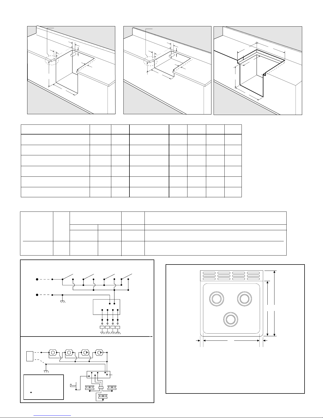
3. Cabinet dimensions needed for each model are shown in CABINET &
COUNTER CUT OUT CHART. The cabinet cut-out must be located
with respect to the minimum clearances to combustible materials as
noted. When planning the location, consider curtains or other com-
bustible materials installed around the range or cooktop.
Note: For models having suffix “N” (i.e. RA1732 BGPN) Countertops with
an overhang must be notched as shown in the illustrations. The notch
should be 7/16˝ minimum, both sides.
WARNING
FIRE AND/OR EXPLOSION
• KNIFE RACK INSTALLATION - Gas supply pipe must be installed with clear-
ance from knives contacting or cutting gas lines.
4. When the cabinet has been prepared according to the dimensions
given and the gas line is in place, remove the range or cooktop
from its packaging and position the range or cooktop in the opening.
5. Verify the range or cooktop is level from side to side and front to rear.
6. Remove the cooking grate(s), slide the range top back about 1/8”, then
lift up on one of the front corners (FIG 3) to remove the range top.
7. Fasten the range or cooktop in place with wood screws (not supplied)
through holes in burner box. Care should be taken to not force the
range mounting flanges to bend, which may cause the range or cook-
top to be mounted too low in the cabinet cutout.
8. Make the gas connection. All openings in the cabinetry around the
gas line must be closed at time of installation. RA, CA series with
electronic ignition: Complete the electrical connections as shown in
the WIRING DIAGRAM. For galley slide-out applications, it is highly
recommended that the negative 12 volt connection be connected
directly to the battery. Voltage supply must be between 9 and 13
VDC. Appliance electrical rating is 12VDC, 0.6A during sparking.
CAUTION
PRODUCT DAMAGE HAZARD
• Connect to 12VDC service only.
• DO NOT connect to a circuit fused for more than 3 amps.
• DO NOT hi-pot range unless electronic ignition system has been
disconnected.
9. Turn on the gas supply.
WARNING
EXPLOSION OR FIRE
• DO NOT use matches, candles or other sources of ignition to test
fittings and gas lines for leaks.
10. Check all connections for gas leaks using a non-corrosive leak
detection fluid. Do not use a soap and water solution. Leak test in
excess of 8 oz. per square inch (1/2 psi) of air pressure will invali-
date warranty.
11. Replace range top (FIG 4-5). Range/cooktop is now ready for operation.
TOP BURNER OPERATION
WARNING
BURN INJURY, FIRE AND/OR EXPLOSION
• Use range or cooktop only for use as described in this manual.
• DO NOT leave children alone or unattended in area where range or cook-
top is in use. Never allow anyone to sit, stand, or climb on any part of
the range cooktop. They could be burned or injured.
• DO NOT store things children might want above the range or cooktop.
Children could be burned or injured while climbing on it.
• DO NOT wear loose or hanging garments when using the range or cooktop.
They could ignite if they touch an open flame and you could be burned.
• Use only dry potholders. Moist or damp potholders on hot surfaces may
result in burns from steam. Do not let the potholder touch an open flame.
DO NOT use a towel or bulky cloth for a potholder. It could catch on fire.
• DO NOT heat unopened containers. They could explode. The hot contents
may cause burns and container particles may cause injury.
• DO NOT use range or cooktop for warming or heating vehicle. You could
be burned or injured, a fire could start, or deplete oxygen in the vehicle.
• DO NOT store flammable materials on, in, or near the range or cooktop.
Any fumes can create an explosion and/or fire hazard.
WARNING
BURN INJURY, FIRE AND/OR EXPLOSION
• All control knobs must be turned to OFF when not in use. Fire and/or
burning hazard may occur if a burner is accidentally left ON.
• DO NOT operate range or cooktop if it is damaged or not working properly.
• Know where your vehicle’s main LP gas shutoff is located.
• Verify sufficient gas supply before attempting to light any top burner. Air in
the gas supply line will significantly delay burner ignition, and a burner may
light unexpectedly as the air in the line clears out and is replaced by LP
gas; this unexpected ignition may burn you. Air may be introduced into the
supply line when the vehicle gas bottle is replaced, during servicing of other
gas appliances, etc.
• If any burner should extinguish (after initially lighting or due to accidental
blow-out), turn all burner knobs clockwise to OFF and WAIT FIVE (5)
MINUTES before again attempting to light the burner.
• DO NOT touch top burners, burner grates, or other areas near top burners
during and after use. Do not let clothing or other flammable materials to
contact top burners or areas near top burners until they have had sufficient
time to cool.
• Make sure the utensils you use are large enough to contain food and avoid
boil overs and spillovers. Heavy splattering or spillovers left on the cooktop
can ignite and burn you.
•
DO NOT
drop pans on the porcelain surface. Cracks or chips in the
porcelain surface may result.
• Be sure that glass cooking utensils are safe for use on the cooktop. Only
certain kinds of glass utensils are suitable for surface or top burner use
without breaking due to the sudden changes in temperature.
• Never leave top burners unattended. A boil over could result and cause
smoking and greasy spillovers that may ignite.
• Turn pan handles inward, but not over other top burners. This reduces the
chance of burns due to bumping pan.
• Grease is flammable. Never allow grease to collect around top burners or
on cooktop surface. Wipe spillovers immediately.
• DO NOT use water on grease fires. Never pick up a flaming pan. Smother a
flaming pan with a tight-fitting lid or cookie sheet. Flaming grease outside of
the pan can be extinguished with baking soda or a multipurpose dry chemi-
cal or foam-type fire extinguisher.
• Use care when lighting a top burner by hand. If the burner lights unex-
pectedly, or your hand is close to the burner, you may be burned.
• Burner flame should not extend beyond the edge of the cooking utensil.
The flame could burn you and cause poor cooking results.
1. Check that gas is on at shutoff valve.
2. LIGHTING Top Burners:
a. All burner controls operate counter-clockwise and must be
pressed inward (toward the cooktop) to turn ON or LITE. Do not
attempt to light more than one burner at a time.
b. IMMEDIATELY light the burner by holding a lit match or a hand-held
spark igniter designed for this purpose near the burner ports.
c. To extinguish the top burner flame, turn the appropriate burner knob
clockwise to OFF.
LIGHTING Top Burners with spark ignition: (FIG 4-5)
a. Turn the appropriate burner knob counter-clockwise to ON or LITE.
Do not attempt to light more than one burner at a time.
b. Turn the SPARK knob clockwise one “click”. If the burner fails to
light, continue turning the SPARK knob clockwise until the burner
lights.
c. To extinguish the top burner flame, turn the appropriate burner knob
clockwise to OFF.
LIGHTING Top Burners with electronic ignition:
a. Turn the appropriate burner knob counterclockwise to ON or LITE.
This will automatically activate the ignition system, and all burners will
begin to spark repeatedly. This is the “clicking” sound you will hear.
b. The burner will light within five (5) seconds. Once the burner is lit, turn
the knob counterclockwise to the desired setting.
c. To extinguish the top burner flame, turn the appropriate burner knob
clockwise to OFF.
d. If 12 VDC power is not available to the ignition module for any reason,
top burners may be lit manually. See instructions in “Lighting Top Burners”.
CAUTION
PRODUCT DAMAGE HAZARD
• DO NOT cook with the control knob set in the LITE position.
Damage to the ignition module and burner electrodes may result.
2

3
3. Proportional flow (linear) top burner valves are installed. Start cooking
at the HI setting, then turn the control knob counter-clockwise to con-
tinue cooking and obtain best results. Use the following table as a guide
until you get used to the setting.
SETTING RECOMMENDED USE
LITE •To light the burner
HI •To start foods cooking
•To bring liquids to a boil
MED •To hold liquids at a boil
9-6 •To fry chicken or pancakes
•To cook large amounts of vegetables
LOW - 5- Low •To keep food warm
CAUTION
PRODUCT DAMAGE HAZARD
• DO NOT use oversized cookware. The pan should not be more than one
inch larger than the burner grate. The maximum pan size is a 10-inch
skillet. Oversized cookware will cause excessive heat build-up in the
stove top and will result in damage to the burner grate, burner and cooktop.
• DO NOT use a broiler pan, griddle, or any other large utensil which covers
more than one (1) top burner at a time. This will create excessive heat
which may cause melting, sooting or discoloration damage to the burn-
er grates, range top, or utensils.
• DO NOT leave an empty utensil, or one which has boiled dry, on a hot top
burner. The utensil could overheat and damage the utensil or the cook-
ing appliance.OVEN OPERATION
WARNING
FIRE, EXPLOSION, BURN INJURY,
CARBON MONOXIDE POISONING
• DO NOT touch any inner surfaces of the oven or oven door, or the wire
rack inside, or any utensils inside the oven during and after use until
these areas have had sufficient time to cool. You could be burned or
injured. During and after use, do not let clothing or other flammable
materials contact these areas until they have had sufficient time to cool.
• DO NOT touch the outer surface of the oven door or the oven vent while the
oven is in use. These areas become hot enough to cause burns. During and
after use, do not let clothing or other flammable materials contact these
areas until they have had sufficient time to cool.
• DO NOT cover the ventilation holes in the oven broiler shelf (shelf above
oven burner). The air circulation inside the oven will be interrupted and
cooking times will vary from normal; food may be burned or under-
cooked.
• DO NOT cover the oven vent openings while the oven is in operation; restrict-
ing the flow of combustion air may create a carbon monoxide poisoning haz-
ard.
• DO NOT use oven as a storage area.
• If oven pilot should extinguish after initial lighting or due to accidental
blowout, turn oven knob clockwise to OFF and wait five (5) minutes
before again attempting to light oven.
1. Check that gas is on at shutoff valve.
2A. LIGHTING THE OVEN PILOT - Match Lit
a. Push in oven control knob FIG 1-A and rotate counter-clockwise to
PILOT ON - PUSH/HOLD.
b. PUSH the knob in and HOLD it in while holding a lit match under the
oven pilot FIG 1-C located near the back of the oven, under the broil-
er shelf FIG 1-B and to the right of the oven burner FIG 1-D.
c. Continue to hold the oven control knob in for 5 seconds after pilot is
lit. Release knob and verify pilot stays lit. Repeat steps (b) and (c) if
pilot does not stay lit.
2B. LIGHTING THE OVEN PILOT - Electronic Spark Lighting
a. Push in oven control knob FIG 1-A and rotate counter-clockwise to
PILOT - PUSH/HOLD.
b. PUSH the knob in and HOLD it in while observing the oven pilot
FIG 1-C located near the back of the oven, under the broiler shelf
FIG 1-B and to the right of the oven burner FIG 1-D.
c. Continue to hold the oven control knob in for 5 seconds after pilot is
lit. Release knob and verify pilot stays lit. Repeat steps (b) and (c) if
pilot does not stay lit.
CONTINUE for both MATCH LIT and ELECTRONIC SPARK LIGHTING -
d. Set the oven control knob to PILOT PUSH/HOLD to maintain pilot
flame. The oven and broiler are now ready for operation; see #3
below before proceeding. The oven pilot has been factory set and
requires no further adjustment.
e. To extinguish the oven pilot, push in the oven control knob
FIG 1-A and rotate clockwise to OFF. Extinguish all pilots when
refueling or traveling.
3. LIGHTING THE OVEN BURNER:
a. Light the oven pilot as described in #2 above.
b. With the oven control knob set to PILOT PUSH/HOLD, push in and
rotate the knob counter-clockwise to the desired temperature set-
ting or to BROIL. The oven will pre-heat in approximately 15 min-
utes. For best results, always pre-heat the oven before use.
c. To extinguish the oven burner, rotate the knob clockwise to PILOT
PUSH/HOLD. The oven pilot will remain lit.
d. For complete shutdown, push in and rotate the knob clockwise to
OFF.
4. USING THE BROILER:
a. Light the oven pilot as described in #2 (above).
b. Push in and rotate the oven control knob counter-clockwise to
BROIL.
c. Center a broiler pan under the broiler flame.
d. Move and turn the food over frequently to ensure even browning and
cooking.
Note: A 2-piece enameled broiler pan (MPD 51042) may be purchased from
Atwood.
Note: Cooking times will be longer at higher attitudes (+4000 feet).
MAINTENANCE
WARNING
BURN INJURY, FIRE AND/OR EXPLOSION
• Make sure all controls are OFF and the range or cooktop is cool
before cleaning.
• Make sure that all cooktop surfaces, burner grates and burners are
cool before cleaning or disassembling cooktop.
• DO NOT use oven cleaners, bleach, or rust removers on the cooktop
or burner grates.
• DO NOT obstruct the flow of combustion and ventilation air.
• Keep appliance area clear of combustible materials, gasoline and
other flammable vapors and liquids.
• Clean oven with oven cleaner only. Follow directions on the container.
•
N
ever use a wire brush or metallic item for cleaning burner ports
or orifices. Brush may “shed” bristles, that may lodge in the orifice
or burner ports and cause a fire or explosion.
CAUTION
PRODUCT DAMAGE HAZARD
• Clean all surfaces as soon as possible after boil overs or spillovers.
• Use warm soapy water only to clean the burner grates, cooktops, paint-
ed surfaces, porcelain surfaces, stainless steel surfaces and plastic
items on your range or cooktop. Do not use grit or acid-type cleaners.
• DO NOT use steel wool, or abrasive cleaners, or acid type cleaners
such as chlorine bleach on your cooktop or grate systems. They
will damage your range or cooktop. Use only non-abrasive plastic
scrubbing pads.
• DO NOT allow foods containing acids (such as lemon or tomato juice, or
vinegar) to remain on porcelain or painted surfaces. Acids may
remove the glossy finish. Wipe up egg spills when cooktop is cool.
• DO NOT wash warm porcelain surfaces. Allow these areas to cool
before cleaning. You could burn yourself, or the porcelain could crack.
• Pitting and discoloration will result if spills are allowed to remain
for any length of time on stainless steel.
•
DO NOT allow spillovers to remain on the burner caps. The caps
could become permanently stained.
•
When cleaning around the burners, use care to prevent damage to
the electrode (if so equipped). If a sponge or cloth should catch
the metal igniter electrode, it could damage or break the electrode.
If this occurs, the burner will not light.

4
The owner’s cooking habits and cleanliness will affect the operation of
the range or cooktop. Proper installation and care will help keep your
range or cooktop looking and operating like new. Most cleaning can
be performed using normal household items.
RANGE & SLIDE-IN COOKTOP:
1. To remove the range top:
All Models - Push firmly in the back of the top to slide the entire top
backwards. While the top is slid backwards, lift up on one of the
two front corners (FIG 3).
2. To replace the range top:
a. RV & CV Models - Place the top on the range (FIG 4) so that the
tabs on the spring clips fit into the slots on the top (FIG 4-B). Push
backwards on the top until the bracket on the front of the top fits
into the notch in the front control panel (FIG 5).
b. RA & CA Models - Place the top on the range (FIG 4) so that the
tabs on the spring clips into the slots on the top (FIG 4-B). Attach
spark wires to burners (FIG 4-A), routing the wires away from the
center of the burner. Rotate the top downward making sure that
all three burner tubes fit up into the burner caps (FIG 4-C). This
may be made easier by using a side to side motion when rotating
the top down. Once the tubes are up into the burner caps push
backwards on the top until the bracket on the front of the top fits
into the notch in the front of the control panel (FIG 5).
3. To remove burner grates:
a. RV and CV Models - simply lift grate up and remove. Replace by
placing two legs at a time into the retaining grommets.
b. RA & CA Models - lift grate up by rotating up away from center of
stove (fig 2). Replace by placing legs into silicone retaining grom-
met and rotating back down on cooktop.
Clean all surfaces quickly after boil over or spillovers. Use a dry towel or
cloth to soak up spills.
ALL SURFACES - When surface is cool,
clean with warm soapy water,
rinse and dry with soft cloth
. Additional cleaning measures:
• Control Knobs - pull the knobs straight off the stems to clean.
• Control Panel - You may use a spray glass cleaner, applying
cleaner to a paper towel (do not spray directly on panel.)
• Cook Top Surface - You may use a mild liquid cleaner/glass cleaner.
• Surface Burner Grates - They should be cleaned as soon as they
become dirty. You may need to use a non-abrasive plastic scrub-
bing pad.
• Surface Burners, Burner Ports or Orifices - if clogged, gently
brush perforated areas with a lightweight brush (toothbrush) or
carefully clean holes out with a toothpick.
NOTE
: Heavy burned on soil may require repeated cleaning steps
until the soil is completely removed.
NOTE
: The grate and surface of the cook top is covered with porce-
lain coating. Porcelain is a glass/ceramic coating glazed to the
surface of the metal. Porcelain is designed to provide a sur-
face that can withstand high temperatures and maintain an
attractive appearance and make it easier to clean.
STORAGE
Dry all surfaces and burner box, then spray surfaces with an oil base
substance to preserve the surface from rusting during long term stor-
age. Wipe off oil coating before reuse.
RANGE MAINTENANCE & CARE INSTRUCTIONS
CARE OF PORCELAIN
The grates and surface of the cook tops are coated with porcelain. Porcelain is
a glass/ceramic coating glazed to the surface of the metal. Porcelain is
designed to provide a surface that withstands high temperatures, has an
attractive appearance and is easy to care for and clean.
UNACCEPTABLE - WHICH WILL VOID YOUR WARRANTY
• NEVER use steel wool, abrasive cleaners, or acid type cleaners such as
chlorine bleach or dish detergents with lemon fruit acid on any part of your
cook top or grate system.
• DO NOT drop pans on the cook top surface, you may crack or chip the
porcelain surface.
Should the porcelain become cracked, chipped or affected by excessive heat,
the porcelain surface will become unsightly and its effectiveness will be reduced.
GENERAL COOKING INSTRUCTIONS
To quickly bring liquids to a boil or to begin a cooking procedure use a high
flame setting. Reduce the flame to a lower setting to continue cooking. using a
higher flame setting than is necessary to maintain a gentle boil will not cook
food more quickly.
COOKWARE
Acquire cookware that fits the RV environment. Proper cookware will reduce
cooking time, using less energy with better cooking results.
ACCEPTABLE
• A heavy gauge (aluminum or copper) metal pan with a smooth flat bottom
(no more than 10” diameter), straight sides, and a tight fitting lid.
• Cover pan with a lid, food cooks faster when covered, because more heat
is retained.
• Lowering flame size, increases cooking efficiency.
• Use cookware with appropriate utensils.
UNACCEPTABLE - WHICH WILL VOID YOUR WARRANTY
Oversized cookware causes a build up of excessive heat, which results in dam-
age to the burner grate, burners, and cook top. Including the following cook-
ware - but not limited to:
• Griddles
• Any cookware that extends beyond 1” of the grate edge.
• Any cookware that comes into contact with the cook top.
• Woks with support rings which restrict air circulation around the burners.
Excessive heat will cause grates and tops to lose their protective coating,
becoming unsightly in appearance. Airflow is important for cooking,
the warmed air must be allowed to mix with air around the burner.
COOKWARE
Use cookware that fits the RV environment, Proper cookware will reduce cook-
ing time, use less energy, and produce better cooking results.
OVEN HEAT CONTROL AND GENERAL USE
PREHEATING OVEN
For best results, preheat the oven for 15 minutes before use. For baking, do
not select a higher than required temperature to preheat the oven faster, it may
have a negative effect on baking results.
AIR CIRCULATION
Warmed air must circulate freely throughout the oven for food to cook proper-
ly. To prevent undercooked or burned food:
• DO NOT cover or block ventilation holes in the oven broiler shelf
(shelf above the burner).
• DO NOT cover the bottom of the oven with aluminum foil to catch “over flow”.
• DO NOT cover oven racks
with aluminum foil.
• Place the food to be baked
in the center of the oven
with 1”-2” inches space
from the oven wall on all
sides allowing at least 1”-
2” of space on all sides of
the container.
• DO NOT crowd the oven with
assorted pans or block air
passage with an oversized
pan.

Atwood Mobile Products warrants to the original owner and subject to the
below mentioned conditions, that this product will be free of defects in
material or workmanship for a period of two years from the original date of
purchase. Atwood’s liability hereunder is limited to the replacement of the
product, repair of the product, or replacement of the product with a recon-
ditioned product at the discretion of Atwood Mobile Products. This warranty
is void if the product has been damaged by accident, unreasonable use,
neglect, tampering or other causes not arising from defects in material
workmanship. This warranty extends to the original owner of the product
only and is subject to the following conditions:
1. For two years from the date of the original purchase Atwood warrants
that this product will be free of defects in material and workmanship with
the exceptions noted below. This warranty includes reasonable labor
charges required to remove and replace the part. Service calls to the
customer’s location are not considered part of these charges and are
therefore the responsibility of the owner.
2. This warranty does not cover the following items classified as normal
maintenance and/or customer damage.
a. Damage, discoloration or scratches to porcelain enamel or other fin-
ishes from improper use and care.
b. adjustment of gas pressure
c. cleaning or adjustment of any burners
d. cleaning or replacement of burner orifices
e. cleaning or adjustment of pilot and thermocouple
f. damage to glass
g. products purchased for commercial or industrial use.
3. In the event of warranty claim the owner must contact in advance either
an authorized Atwood Service Station or the Atwood Service Department.
Warranty claim service must be performed at an authorized Atwood
Service Station (a list will be provided at no charge) or as approved by
the Atwood Service Department Atwood Mobile Products, 4750
Hiawatha Drive Rockford, IL 61103-12998 USA. Phone 815-877-5700.
4. Return parts must be shipped to Atwood Mobile Products “prepaid”.
Credit for shipping costs will be included with the warranty claim. The
defective parts become the property of Atwood Mobile Products and
must be returned to the Consumer Service Department, Atwood Mobile
Products, Greenbrier Operations, 6320 Kelly Willis Road, Greenbrier, TN
37073 USA.
5. This warranty applies only if the unit is installed according to the installa-
tion instructions provided and complies with local and state codes.
6. The warranty on replacement parts is the unused portion of the original
warranty period.
7. Damage or failure resulting from misuse (including failure to seek proper
repair service) misapplication, alterations, water damage or freezing are
owner’s responsibility.
8. Atwood does not assume responsibility for any loss of use of vehicle,
loss of time, inconvenience, expense for gasoline, telephone, travel,
lodging, loss or damage to personal property or revenues. Some States
do not allow the exclusion or limitation of incidental or consequential
damages, so the above limitations or exclusions may not apply to you.
9. Any implied warranties are limited to two (2) years. Some States do not
allow limitations on how long an implied warranty lasts, so the above limi-
tation may not apply to you. This warranty gives you specific legal rights and
you may also have other rights, which may vary, from State to State.
10. Replacement parts purchased outside the original cooking warranty
carry a 90 day warranty. This includes the part at no charge and reason-
able labor charges to replace it.
This Atwood product is designed for use in recreation vehicles for the pur-
pose as stated in the ‘data plate’. Any other use, unless authorized in writ-
ing by the Atwood Engineering Department, voids the warranty.
Atwood/Wedgewood Vision Products include range/oven, drop-in, slide-in
and high pressure stoves. 3/03
A
B
1 2 3
C
D
5
4
a
b
c
c
side view
5
COOKING APPLIANCE LIMITED WARRANTY

7
ATWOOD & WEDGEWOOD
Oven & Slide-In Cooktop Parts Identification
WEDGEWOOD ATWOOD
ITEM DESCRIPTION RV CV RA CA
1733 2133 33 1733 2133 33
1 Grate - black 56272 56272 56272 57190 57190 57190
2A Grommet (4) 53009 53009 53009 53009 53009 53009
2B Sealed Grate U-Channel 57194 57194 57194
3 Top Spring Clip (2) 51035 51035 51035 51035 51035 51035
4-A Range Top Assy - white 52007 52007 52007 57300 57300 57300
4-B Range Top Assy - black 52008 52008 52008 57299 57299 57299
4-C Range Top Assy - bisque 52009 52009 52009
4-D Range Top Assy - stainless steel 56742 56742 56742 57309 57309 57309
5-A Burner, Piezo - left rear 57205 57205 57205
5-A Burner, Matchlit - left rear 57206 57206 57206
5-B Burner, Piezo - center front 57201 57201 57201
5-B Burner, Matchlit - center front 57202 57202 57202
5-C Burner, Piezo - right rear 57203 57203 57203
5-C Burner, Matchlit - right rear 57204 57204 57204
5-D Burner, Piezo/Electronic Ignition 57276 57276 57276
6 Bushing, Burner (3) 53011 53011 53011 53011 53011 53011
7 Hex Nut (2) 51004 51004 51004
8 Brass Fitting 52294 52294 52294 52294 52294 52294
9 Pressure Regulator 51062 51062 51062 51062 51062 51062
10 3-Burner Manifold 57270 57270 57268 57270 57270 57268
11 Valve thru Bolt 57278 57278 57278 57278 57278 57278
12 Bolt Oven Thermostat thru Bolt (1) 57266 57266 57266 57266
13 Valve, Burner-Mini 9000 BTU (1) 57252 57252 57252 57252 57252 57252
14 Valve, Burner-Mini 6500 BTU (2) 57251 57251 57251 57251 57251 57251
15-A Burner Tube Assy- right rear 57110 57110 57110
15-B Burner Tube Assy- left rear 57108 57108 57108
15-C Burner Tube Assy- center front 57109 57109 57109
15-D Burner Clip, wire (3) 57198 57198 57198
16A Thermostat, oven control 57294 57294 57294 57294
16B Thermostat, oven control w/switch 57265 57265
17 Piezo Ignitor 56096 56096 56096 56096 56096 56096
18 12V Ignition Module 57277 57277 57277
19 Valve Ignition Switch 56163 56163 56163
20A Piezo Knob -black 51344 51344 51344 51344 51344 51344
20B Piezo Knob -white 53223 53223 53223 53223 53223 53223
21A Burner Knob - black 56148 56148 56148 56148 56148 56148
21B Burner Knob - white 53221 53221 53221 53221 53221 53221
22A Oven Thermostat Knob - black 57258 57258 57258 57258
22B Oven Thermostat Knob - white 57291 57291 57291 57291
23 Control Panel Assy- w/o Label ◆◆ ◆ ◆◆◆
24 Control Panel Label ◆◆ ◆ ◆◆◆
25 Burner Box 51687 51687 51687 51687 51687 51687
26 Burner Spring Clips (3) 57107 57107 57107
27 Oven Can 51969 51970 51969 51970
28 Oven rack 51069 51069 51069 51069
29 Oven shelf 51670 51670 51670 51670
30-A Door assembly includes handle - black steel 51977 51983 51977 51983
30-B Door assembly includes handle - white steel 51978 51984 51978 51984
30-C Door assembly includes handle - white glass 51981 51987 51982 51988
30-D Door assembly includes handle - black glass 51980 51986 51980 51986
30-E Door assembly includes handle - stainless steel 51958 51958
30-F Door assembly white handle - white steel 51957 51957
31A Oven Door Handle - black 51124 51124 51124 51124
31B Oven Door Handle - white 51126 51126 51126 51126
32 Orifice Block 57271 57271 57271 57271
33 Pilot Assembly 57250 57250 57250 57250
34 Burner, oven 57275 57275 57275 57275
35 Thermocouple 57274 57274 57274 57274
36 Oven Can Trim 51975 51976 51975 51976
37 Oriface Block Plate 56139 56139 56139 56139
38 Spark Electrode 57292 57292
N/S Wiring Harness - Electronic Ignition Switches 57262 57262 57262
Wiring Lead - Electronic Ignition Electrodes 57261 57261 57261
Wiring Lead - Electronic Ignition Ground 57260 57260 57260
N/S Wiring Lead - Piezo 57264 57264 57264 57264 57264 57264
N/S KIT - Door Seal 51060 51061 51060 51061
N/S KIT - Gas Tube Supply Oven 57273 57272 57273 57272

6
Order by model, color and style ◆commander par couleur
not shown in illustration N/S pas montré
RA Series Range & Slide-In
Piezo and Electronic Ignition
RV Series Range & Slide-In
Match Light and Piezo
4
5D
7
17
16
11
20
21
22
10
26
18
9
8
1
19
32
30 28
36 34 33 32
5A
5B
5C
6
12
13
16
20
21
22
25
17
10
8
9
11
14
1
4
2-A
23
27
24
23
37
29
30
31
28
36 34 33 38
35
32
25
27
37
29
24
3
31
15C
12
26
14 15D
13
15B
2-A
2B
3
15A
6
35

16
A
B
D
E
F
G
C
B
D
E
F
G
C
All Ovens All Slide-In Cooktops
A
G
E
B
A
C
D
F
Recessed Bi-Fold Cover
Notch for N-Series only Notch for N-Series only
CUT OUT DIMENSIONS - DIMENSIONS DE LA DÉCOUPE
CABINET & COUNTER CUT OUT CHART RECESSED BI-FOLD COVER
CUT OUT CHART
RECESSED BI-FOLD COVER - COUVERCLE PLIANT EN DEUX PARTIES ENCASTRÉ
LAMINATE MATERIAL MPD RV & RA OVEN CV & CA
MATÉRIAU STRATIFIÉ PART #17˝ 21˝ SLIDE-IN
AAABCDEFG
1/4˝ 56397 16.0˝ 20.0˝ 3.0˝ 17.75˝ 20.0˝ 2.31˝ 24.5˝ 2.13˝ 20.25˝
6 mm 406 mm 508 mm 76 mm 451 mm 508 mm 59 mm 622 mm 54 mm 514 mm
1/32˝ 56391 16.0˝ 20.0˝ 3.0˝ 17.75˝ 20.0˝ 1.84˝ 24.5˝ 2.13 20.25˝
.8 mm 406 mm 508 mm 76 mm 451 mm 508 mm 47 mm 622 mm 54 mm 514 mm
† Minimum clearance to combustible
materials. (typical two (2) sides and back)
*The overall unit depth for CA models with
Electronic Ignition is 18-1/4˝ from cabi-
net face to back wall of cutout below
counter.
† Éloignement minimum des matériaux
combustibles .(Typiquement sur les deux
côtés et à l’arrière)
*La profondeur totale des modèles CA à
allumage électronique est de
(464 mm). Ces dimensions sont celle de
la découpe entre la façade de l’élément
de cuisine et la paroi arrière du comp-
toir.
ELECTRICAL RATING:
12 VDC. 0.05 A
For 12 VDC service, DO NOT connect
to higher voltage. DO NOT connect
to a circuit fused for more than 3A
SCHEMATIC DIAGRAM FOR ELECTRONIC IGNITION MODELS
R
GR
G
WWW
12 VOLT DC
IGNITION MODULE
SPARK ELECTRODES
TOP BURNERS
Burner Valve
Switches
+
-
Burner Valve Switches
Top Burners
12 volt
Battery
+
–
Ignition
Module
G
R
R
R
W
R
G
W
- - - -
= RED Wire
= GREEN Wire
= WHITE Wire
= Wire Connection
= Wired by Installer
CONNECTION DIAGRAM FOR ELECTRONIC IGNITION MODELS
Thermostat Switch
(if equipped)
W
OVEN PILOT BURNER
(if equipped)
Pilot
Burner
Thermostat Switch (if equipped)
(if
equipped)
A
BB
CD
RECESSED BI-FOLD COVER - COUVERCLE PLIANT EN DEUX PARTIES ENCASTRÉ
RANGE HOOD MOUNTING INFORMATION
ABCD
Range Top 19-3/8˝
Mounting Trim 3/4˝
Range Top Depth 15-7/8˝
Range Top plus Oven Vent 19-9/16˝
AB
(RV/CV) C (RA/CA) DEFG
17" RV & RA Ranges 17.75˝20.25˝1.13˝†2.13˝†16˝0˝1.75˝1.5˝
Série RV et RA 17”451MM 514MM 29MM†54MM†406MM 0MM 45MM 38MM
21" RV & RA Ranges 17.75˝20.25˝1.13˝†2.13˝†20˝0˝1.75˝1.5˝
Série RV et RA 21”451MM 514MM 29MM†54MM†508MM 0MM 45MM 338MM
Slide-In CV & CA 17.75˝*20.25˝1.13˝†2.13˝†3˝0˝1.75˝1.5˝
Série CV et CA àencastrement 451MM 514MM 29MM†54MM†76MM 0MM 45MM 38MM
17" RV & RA-N Series 17.75˝20.25˝1.13˝†2.13˝†16˝7/16˝1.75˝1.5˝
Série RV 43cm RV et RA-N 451MM 514MM 29MM†54MM†406MM 11MM 45MM 38MM
21" RV & RA-N Series 17.75˝20.25˝1.13˝†2.13˝†20˝7/16˝1.75˝1.5˝
Série RV 53cm RV et RA-N 451MM 514MM 29MM†54MM†508MM 11MM 45MM 38MM
Slide-In CV & CA-N Series 17.75˝20.25˝1.13˝†2.13˝†3˝7/16˝1.75˝1.5˝
Série CV àencastrement CV et CA-N 451MM 514MM 29MM†54MM†76MM 11MM 45MM 38MM
CUT OUT DIMENSIONS
DIMENSIONS DE LA DÉCOUPE
CABINET & COUNTER CUT OUT CHART - TABLEAU DE DECOUPE DES ELEMENTS ET DU COMPTOIR
NOTE: Maximum countertop overhang = 3/4”NOTE: rebord maximum du comptoir = 19 mm

Atwood Extended Service
Contract Provides These Extras!
for
PLEASE USE ORDER FORM BELOW TO BEGIN EXTENDED SERVICE CONTRACT OF YOUR PRODUCT(S).
ATWOOD WATER HEATER
inner tank
HYDRO FLAME
FURNACE
combustion chamber ATWOOD/WEDGEWOOD RANGE
gas valves & manifold
■■
■■extends coverage
to full five years ■■
■■one price covers
parts and labor ■■
■■in-shop service
(read complete information on form below)
Also available...
Service Related Travel
✔✔✔
■■
■■Includes mileage travel
expense by authorized
service center
■■
■■Up to 200 miles total
of service travel ■■
■■One full year of
coverage
✔✔✔
ATWOOD EXTENDED SERVICE CONTRACTS
Water Heater Tank—An extended service contract is available covering the parts and labor
for replacement of the inner tank in the event the water heater tank develops leaks due to
corrosion. This extends the original (2) two year warranty an additional (3) three years for
a total of (5) five years to the original owner from the original date of purchase of the water
heater or vehicle.
Furnace Combustion Chamber—An extended service contract is available covering the
parts and labor for the replacement of the combustion chamber in the furnace in the event
the combustion chamber were to prematurely fail due to defects in material or workmanship.
This extends the original (2) two year warranty an additional (3) three years for a total of
(5) five years to the original owner from the date of purchase of the furnace or vehicle.
Range Gas Valves and Manifold—An extended service contract is available covering the
parts and labor for the replacement of range burner valves and manifold in the event of
premature failure due to defects in material and workmanship. This extends the original
(2) two year warranty an additional (3) three years for a total of (5) five years to the original
owner from the original date of purchase of the range or vehicle.
Save $10.00 by selecting all three Extended Service Contracts.
SERVICE RELATED TRAVEL MILEAGE—$20.00 (See Explanation)
Mileage Travel Expense—Mileage travel expense is not covered by the Limited Warranty
issued with each product. If it is anticipated that it may be inconvenient to transport your
vehicle or Atwood product to obtain service you may choose to purchase this Service
Mileage option. This will pay up to 200 miles of service travel at 20 cents per mile to an
authorized Atwood Service Center whose service personnel travels to your location to per-
form in-warranty service work on your Atwood product. This is for (1) one year from the
original date of purchase of the vehicle or Atwood water heater, furnace or range.
To qualify for any of these options, they must be purchased within 90 days of the vehicle or
product purchase. Prices listed are in US DOLLARS-please make check amount accordingly.
Upon receipt of this completed card together with your check or money order, Atwood will
send you a written confirmation of the options you selected.
$45
■■
■■
$25
■■
■■
$15
■■
■■
All 3
$75
■■
■■
$20
■■
■■
EXTENDED SERVICE ORDER FORM
Today’s Date __________________________________________
Date of Purchase________________________________________
Name ________________________________________________
Address ______________________________________________
City ____________________________ ST ____ ZIP __________
Phone ________________________________________________
Your RV Manufacturer’s Brand Name ________________________
Your Dealer’s Company Name ____________________________
CONTRACT DESIRED
Atwood Mobile Products
4750 Hiawatha Drive
Rockford, IL 61103
Model No. Serial No.
ATWOOD Water Heater Tank ____________ __________ $45.00 ■■
■■
HYDRO FLAME Furnace ____________ __________ $25.00 ■■
■■
ATWOOD/WEDGEWOOD Range ____________ __________ $15.00 ■■
■■
Save $10—Select All Three from above ■■
■■
MILEAGE TRAVEL EXPENSE $20.00 ■■
■■

Offer void outside the United States.
Tennessee residents add 8.25% sales tax.
Enclose check or money order in U.S. dollars.
Allow 4-6 weeks for delivery.
Please send me these Wedgewood accessories.
Mail in orders only. No C.O.D.s or charge card orders
WEDGEWOOD MODEL #
NAME
ADDRESS
CITY ST ZIP
Qty. Description Part # Price Sub Total
■■
■■2-Piece broiler pan 51042 $25.95
Bifold Range Cover
■■
■■White Cover 56418 $44.95
■■
■■Black Cover 56417 $44.95
Lift-Up Drop-In Cooktop Cover - DV Series*
■■
■■2-burner ss w/windguard 56459 $44.95
■■
■■3-burner ss w/windguard 56461 $49.95
Prepaid UPS Charges of $4.50 per item
*DA Series please call Atwood Greenbrier TOTAL
▼ COPY ORDER FORM AND MAIL IN WITH PAYMENT ▼
PHONE:615•643•4556 FAX:615•643•4616
Atwood Mobile Products
6320 Kelly Wills Road
Greenbrier, TN 37073
INTERNET: http://www.atwoodmobile.com
Wedgewood Accessories
Full-Size Broiler Pan
This beautiful two-piece broiler pan, designed especially for your
Wedgewood range, has a durable, easy-to-clean porcelain enamel
finish for trouble-free broiling.
Bi-Fold Range Cover and Backsplash
This two-in-one accessory provides extra counterspace when
closed and protects the wall behind the stove while you are
cooking.
Available in white or black.
Lift-Up Drop-in Cover
This attractive cover for Wedgewood drop-in units adds valuable counter
space—a must for camping. Available for two-and-three burner units in
stainless steel. The cover comes completely assembled, with mounting
screws and rubber corner guards.
(D Models Only)
Save on these popular accessories!
Order a broiler pan, a lift-up cooktop cover or a bi-fold cover/backsplash
direct from Wedgewood and save.
8/03
ATWOOD SEALED BURNER WEDGEWOOD VISION RANGE
Other manuals for RV
1
This manual suits for next models
4
Table of contents
Other Atwood Range manuals
Popular Range manuals by other brands

Viking
Viking BVGRC8366BWSS Use & installation guide

Blodgett
Blodgett Saffire B36A-BBB-SU Specification sheet

Lotus cooker
Lotus cooker BR-6ET Instructions for installation and use

GE
GE Profile PGS950SEF quick start guide

KitchenAid
KitchenAid KDRS505X Specification sheet

GE
GE PB920TPWW - Profile 30" Electric Ran Technical service guide