ATX SignalOn Series User manual

INSTALLATION & OPERATION MANUAL
L-Band Splitter Module
www.atxnetworks.com
www.atxnetworks.com
1.2 GHz
D3.1/CCAP
™
Compliant
SignalOn
®
Series

SignalOn®Series, MAXNET®, HFC Enhance®, PCI Filters®, Q-Series®& FiberLinx®are registered trademarks of ATX in the United States and/or other countries. SMACSM is a
service mark of ATX in the United States and/or other countries. Products or features contained herein may be covered by one or more U.S. or foreign patents. Other non-ATX
product and company names in this manual are the property of their respective companies.
Although every effort has been taken to ensure the accuracy of this document it may be necessary, without notice, to make amendments or correct omissions.
Specications subject to change without notice.

TABLE OF CONTENTS
Page
Introduction........................................................................................................................................................ iii
Admonishments ................................................................................................................................................ iii
General Safety Precautions.............................................................................................................................. iii
Certication........................................................................................................................................................ iii
FCC Compliance Statement ............................................................................................................................. iii
1. GENERAL.................................................................................................................................................. 1-1
2. PRODUCT DESCRIPTION........................................................................................................................ 2-1
3. SPECIFICATIONS ..................................................................................................................................... 3-1
3.1. Functional Diagram ........................................................................................................................... 3-3
4. INSTALLATION ......................................................................................................................................... 4-1
5. SERVICE & SUPPORT.............................................................................................................................. 5-1
5.1. Contact ATX Networks....................................................................................................................... 5-1
5.2. Warranty Information ......................................................................................................................... 5-1
5.3. Safety ................................................................................................................................................ 5-1
SignalOn®Series – L-Band Splitter Module – Installation & Operation Manual i

Index of Tables
Tables
#1 Power Passing Ports .............................................................................................2-1
Figures
#1 2–way Splitter Functional Diagram........................................................................3-3
#2 4–way Splitter Functional Diagram........................................................................3-3
#3 8–way Splitter Functional Diagram........................................................................3-3
ii SignalOn®Series – L-Band Splitter Module – Installation & Operation Manual

Introduction
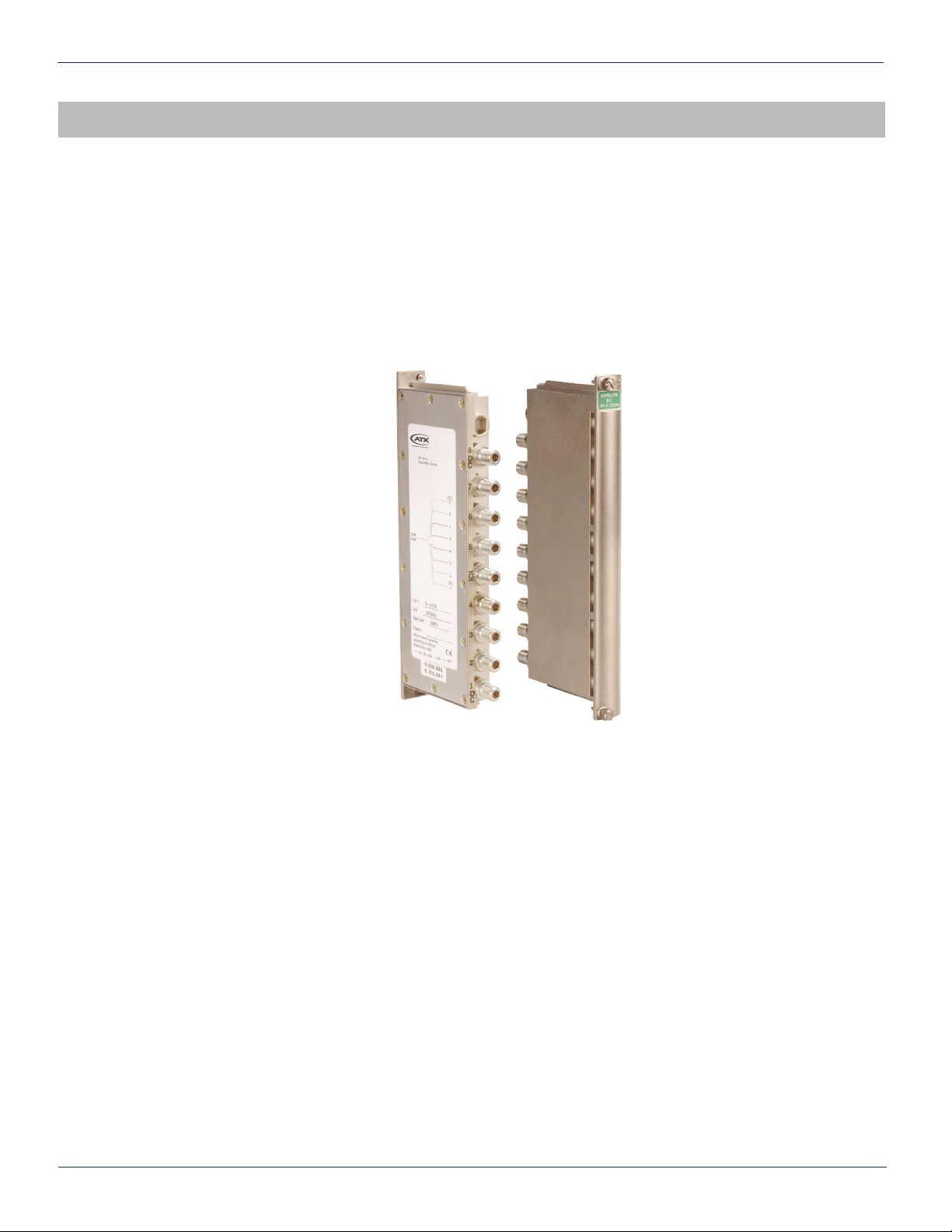
The SignalOn Series L-Band Module is designed to be installed in the 4-, 8-, or 20-position SignalOn Series chassis. Each
module occupies one positions in the chassis. The mechanical dimensions, cable management, and aesthetics of the L-Band
Module are compatible with the SignalOn product line. The system is designed to accommodate superior cable management
and ease of use.
Admonishments
Important safety admonishments are used throughout this manual to warn of possible hazards to persons or equipment.
An admonishment identi es a possible hazard and then explains what may happen if the hazard is not avoided. The
admonishments — in the form of Dangers, Warnings, and Cautions — must be followed at all times. These warnings are
fl agged by use of the triangular alert icon (seen below), and are listed in descending order of severity of injury or damage
and likelihood of occurrence.
Danger: Danger is used to indicate the presence of a hazard that will cause severe personal injury, death, or substantial
property damage if the hazard is not avoided.
Warning: Warning is used to indicate the presence of a hazard that can cause severe personal injury, death, or substantial
property damage if the hazard is not avoided.
Caution: Caution is used to indicate the presence of a hazard that will or can cause minor personal injury or property
damage if the hazard is not avoided.
General Safety Precautions
Warning: Wet conditions increase the potential for receiving an electrical shock when installing or using electrically-powered
equipment. To prevent electrical shock, never install or use electrical equipment in a wet location or during a lightning
storm.
Certication
SignalOn Forward Path products have been tested and found to comply with the requirements of UL 60950, and CSA 22.2
No. 0.7, emissions EN55022 radiated and conducted.
FCC Compliance Statement
The SignalOn Forward Path Ampli er product line has been certi ed to comply with the requirements for class A computing
devices per part 15 of the FCC regulations.
Warning: This equipment generates, uses, and can radiate radio frequency energy and if not installed and used in accordance
with the instruction manual, may cause interference to radio communications. It has been tested and found to comply with
limits for a Class A digital device pursuant to Subpart B of Part 15 of FCC Rules, which are designed to provide reasonable
protection against such interference when operated in a commercial environment. Operation of this equipment in a residential
area is likely to cause interference to TV and radio reception in which case the user, at their own expense, will be required to
take whatever measures may be required to correct the interference.
This equipment does not exceed Class A limits for radio emission for digital apparatus, set out in the radio interference
regulation of the authorization methods of Industry Canada. Operation in a residential area may cause unacceptable
interference to TV and radio reception requiring the owner or operator to take whatever steps are necessary to correct the
interference.
SignalOn®Series – L-Band Splitter Module – Installation & Operation Manual iii
PREFACE

PREFACE
iv SignalOn®Series – L-Band Splitter Module – Installation & Operation Manual
This page left intentionally blank.

PREFACE
GENERAL
1. General
The SignalOn system is a modular system that permits high isolation splitting and switching of headend signals in a CATV
system. The system is designed to accommodate strong cable management, EMI shielding, and ease of use. This facilitates
easy recon guration and high performance within a dynamic headend environment.
The SignalOn L-Band Splitter Module is designed for use with the SignalOn 4-position, 8-position, or 20-position chassis. All
RF connections to the splitter are made through standard 75 Ohm BNC, or F connectors located on the rear. Each SignalOn
Splitter Module occupies one position in a chassis. A splitter module is shown on the front of this publication. Each module
can be used as either a splitter or a combiner.
SignalOn®Series – L-Band Splitter Module – Installation & Operation Manual 1-1
CHAPTER 1: GENERAL

1-2 SignalOn®Series – L-Band Splitter Module – Installation & Operation Manual
CHAPTER 1: GENERAL
This page left intentionally blank.

CHAPTER 1: GENERAL
PRODUCT DESCRIPTION
2. Product Description
L-Band microwave signals operating in the 950 MHz to 2.145 GHz frequency band are received from a satellite downlink
antenna. Signals are then typically fed to multiple satellite receivers such as analog receivers, analog Integrated Receiver/
Decoders or digital Integrated Receiver/Transcoders. When these multiple receiving devices are fed from the same satellite
antenna, it is necessary to split the downlink signal into several equal outputs. These split signals are then fed to each
receiving device individually.
Each splitter conguration has two ports that pass DC voltage(s) from the receiver(s) assigned to supply power to the Low
Noise Block (LNB). Table 1 shows the power pass port assignment for each individual module type.
SignalOn®Series – L-Band Splitter Module – Installation & Operation Manual 2-1
CHAPTER 2: PRODUCT DESCRIPTION
Table #1: Power Passing Ports
MODULE TYPE DC POWER PASSING PORTS MAXIMUM POWER RATING
2–way 1 & 2 24 VDC at 1 Ampere
4–way 1 & 4 24 VDC at 1 Ampere
8–way 1 & 8 24 VDC at 1 Ampere

2-2 SignalOn®Series – L-Band Splitter Module – Installation & Operation Manual
CHAPTER 2: PRODUCT DESCRIPTION
This page left intentionally blank.

CHAPTER 2: PRODUCT DESCRIPTION
SPECIFICATIONS
3. Specications
Please refer to the SignalOn L-Band Satellite Splitter Modules data sheet located at atxnetworks.com for specications.
3.1. Functional Diagrams
SignalOn®Series – L-Band Splitter Module – Installation & Operation Manual 3-1
CHAPTER 3: SPECIFICATIONS
PASS
PASS
4-way Splitter
1
2
3
4
PASS
PASS
2-way Splitter
1
2
PASS
PASS
8-way Splitter
1
2
3
4
5
6
7
8
Figure #2: 4-way Splitter Functional Diagram
Figure #1: 2-way Splitter Functional Diagram
Figure #3: 8-way Splitter Functional Diagram

3-2 SignalOn®Series – L-Band Splitter Module – Installation & Operation Manual
CHAPTER 3: SPECIFICATIONS
This page left intentionally blank.

CHAPTER 3: SPECIFICATIONS
INSTALLATION
4. Installation
Each splitter module occupies a single slot in the chassis. Use the following procedure to install modules in the SignalOn
Series chassis.
1. Make sure the ATX logo (or any other front panel lettering) is readable. Slide the plug-in module into its designated
location in the chassis.
Warning: Never install equipment in a wet location or during a lightning storm.
2. Secure the module using its two captive retaining screws.
3. After each module is loaded into the chassis, refer to your work order, and connect the designated RF cables to the
appropriate BNC or F connectors on the modules in the chassis.
4. Carefully route cables through the cable management slots located on each side of the rear of the chassis. Use the
cable management guidelines found in this manual to route cable from the chassis to the rack/cabinet.
5. Perform any cabling or operational tests required at your facility.
SignalOn®Series – L-Band Splitter Module – Installation & Operation Manual 4-1
CHAPTER 4: INSTALLATION

This page left intentionally blank.
3-4 SignalOn®Series – L-Band Splitter Module – Installation & Operation Manual
CHAPTER 4: INSTALLATION

SERVICE & SUPPORT
5. Service & Support
5.1. Contact ATX Networks
Please contact ATX Technical Support for assistance with any ATX products. Please contact ATX Customer Service to obtain
a valid RMA number for any ATX products that require service and are in or out-of-warranty before returning a failed module
to the factory.
RF Products
(MAXNET, SignalOn, HFC Enhance, PCI Filters, Q-Series, SCN, SMAC, FiberLinx)
TECHNICAL SUPPORT
Tel: (905) 428-6068 – press *3 then press 2
Toll Free: (800) 565-7488 – press *3 then press 2 (USA & Canada only)
Email: [email protected]
CUSTOMER SERVICE
ATX Networks
1-501 Clements Road West
Ajax, ON L1S 7H4 Canada
Tel: (905) 428-6068 – press *1
Toll Free: (800) 565-7488 – press *1 (USA & Canada only)
Fax: (905) 427-1964
Toll Free Fax: (866) 427-1964 (USA & Canada only)
Email: [email protected]
Web: www.atxnetworks.com
5.2. Warranty Information
All of ATX Networks’ products have a 1-year warranty that covers manufacturer’s defects or failures.
5.3. Safety
IMPORTANT! FOR YOUR PROTECTION, PLEASE READ THE FOLLOWING:
WATER AND MOISTURE: Care should be taken so that objects do not fall and liquids are not spilled into the enclosure
through openings.
POWER SOURCES: The device should be connected to a power supply only of the type described in the operating
instructions or as marked on the device.
GROUNDING OR POLARIZATION: Precautions should be taken so that the grounding or polarization means of the device
is not defeated.
POWER CORD PROTECTION: Power supply cords should be routed so that they are not likely to be pinched by items
placed upon or against them, paying particular attention to cords at plugs, convenience receptacles, and the point where
they exit from the device.
SERVICING: The user should not attempt to service the device beyond that described in the operating instructions. All other
servicing should be referred to quali ed service personnel.
FUSING: If your device is equipped with a fused receptacle, replace only with the same type fuse. Refer to replacement text
on the unit for correct fuse type.
SignalOn®Series – L-Band Splitter Module – Installation & Operation Manual 5-1
CHAPTER 4: INSTALLATION CHAPTER 5: SERVICE & SUPPORT

ATX Networks
1-501 Clements Road West, Ajax, ON L1S 7H4 Canada
ISO
9001:15
REGISTERED
© 2018 ATX Networks
Printed in Canada
Information in this document is subject to change without notice.
www.atxnetworks.com
Rev. 06/18 (ANW0848)
Other manuals for SignalOn Series
3
Table of contents
Popular Cables And Connectors manuals by other brands

SeaLevel
SeaLevel SeaLINK+485 user manual

PCB Piezotronics
PCB Piezotronics 010D30 Installation and operating manual

CYP
CYP CLUX-18S Operation manual

Gefen
Gefen EXT-HDMI1.3-145 user manual

Gefen
Gefen HDSDI-144N user manual

Gleason Reel
Gleason Reel Universal Cable Reel-Drive Drive UE32 Installation and maintenance instructions