ATX MAXNET II Platinum Series User manual

MPAC/MPDC Modular Power Supply
Installation & Operation Manual
CCAP™
Com
pliant
1.2 GHz

MAXNET®II is a registered trademark of ATX in the United States and/or other countries. Products or features contained herein may be covered by one or more U.S. or foreign
patents. Other non-ATX product and company names in this manual are the property of their respective companies..
Although every effort has been taken to ensure the accuracy of this document it may be necessary, without notice, to make amendments or correct omissions.
Specications subject to change without notice.

TABLE OF CONTENTS
Page
1. PRODUCT DESCRIPTION........................................................................................................................ 1-1
1.1. Functional Diagrams.......................................................................................................................... 1-2
1.2. Technical Specications .................................................................................................................... 1-3
2. INSTALLATION ......................................................................................................................................... 2-1
2.1 Product Inspection............................................................................................................................. 2-1
2.2. Module Installation Into the Active MAXNET®II Chassis .................................................................. 2-1
2.3. DC Redundant Powering of Active MAXNET®II Chassis ................................................................. 2-2
2.4. Remote Powering of Additional Active MAXNET®II Chassis’ ........................................................... 2-2
2.5. Module Power Requirements ............................................................................................................ 2-3
2.6 LED Indicators................................................................................................................................... 2-3
3. STATUS MONITORING ............................................................................................................................. 3-1
3.1. Chassis Interface Options ................................................................................................................. 3-1
3.2. SCTE HMS MIB Software Denition of Module................................................................................. 3-1
3.3. Web Interface .................................................................................................................................... 3-1
3.4. Updating Active Chassis Firmware.................................................................................................... 3-2
3.5. Factory Reset .................................................................................................................................... 3-2
4. STATUS MONITORING FEATURES ......................................................................................................... 4-1
4.1. SNMP Parameters............................................................................................................................. 4-1
4.2. SNMP MIBs Required for MPAC & MPDC ........................................................................................ 4-2
5. MAINTENANCE & TROUBLESHOOTING................................................................................................ 5-1
5.1. Maintenance...................................................................................................................................... 5-1
5.2. Troubleshooting................................................................................................................................. 5-1
6. SERVICE & SUPPORT.............................................................................................................................. 6-1
6.1. Contact ATX Networks....................................................................................................................... 6-1
6.2. Warranty Information ......................................................................................................................... 6-1
6.3. Safety ................................................................................................................................................ 6-1
MAXNET®II – MPAC/MPDC Modular Power Supply – Installation & Operation Manual i

Index of Figures and Tables
Figures
#1 MPAC Power Supply Functional Diagram ...................................................1-2
#2 MPDC Power Supply Functional Diagram...................................................1-2
#3 Front & Rear Panel Pictures........................................................................2-2
#4 Remote Powering ........................................................................................2-2
#5 Redundant Powering ...................................................................................2-2
Tables
#1 Ordering Information....................................................................................1-1
#2 Technical Specications ..............................................................................1-3
#3 Rear Terminal Block Assignments ...............................................................2-1
#4 LED Status Indications ................................................................................2-3
#5 Common Module SNMP Parameters ..........................................................4-1
#6 MPAC & MPDC SNMP Parameters.............................................................4-1
#7 SCTE HMS MIBs Required .........................................................................4-2
ii MAXNET®II – MPAC/MPDC Modular Power Supply – Installation & Operation Manual

PRODUCT DESCRIPTION
1. Product Description
The MPAC and MPDC are modular power supplies that supply the required +24 VDC to the MAXNET II Active Chassis
back plane. This allows any MAXNET II active module (RPR’s, FPT’s, AMP’s, RF switcher) to be installed in any remaining
active chassis slot to receive power. Both MPAC and MPDC have 24 VDC redundant powering capabilities, although
only the MPDC offers true load sharing logic. Installing two power supply modules into a chassis will thus ensure power
to the backplane if one of them fails. Both the MPAC and MPDC include a 24 VDC rear terminal block connection for
remote powering options. The MPAC and MPDC power supply modules are dual-width, taking up two slots in the Active
MAXNET II Chassis. They are connected to the Active MAXNET II Chassis through a hot-swapping backplane. The MPAC
and MPDC modules feature the standard MAXNET II functionality including front panel power and alarm LED indicators as
well as the capability of module status monitoring through SNMP based Managers. The MAXNET II SNMP interface is HMS
compliant.
Please refer to the web page for up-to-date specications – www.atxnetworks.com
MAXNET®II – MPAC/MPDC Modular Power Supply – Installation & Operation Manual 1-1
CHAPTER 1: PRODUCT DESCRIPTION
Table #1: Ordering Information
Part Number Description
MPAC-110 110 VAC to 24 VDC 250W Power Supply
MPAC-220 220 VAC to 24 VDC 250W Power Supply
MPDC -48 VDC to 24 VDC 250W Power Supply

1.1. Functional Diagrams
1-2 MAXNET®II – MPAC/MPDC Modular Power Supply – Installation & Operation Manual
CHAPTER 1: PRODUCT DESCRIPTION
Figure #1: MPAC Power Supply Functional Diagram
ATTENTION: NOT A UNIVERSAL
VOLTAGE INPUT !
REFER TO ORDERING
INFORMATION FOR DETAILS
Figure #2: MPDC Power Supply Functional Diagram
POWER SUPPLY
MODULE
FUSE
6.3A
(3.15A for 220V)
250V
FUSE
15A
250V
MONITOR AND CONTROL
110 or
220 VAC
IN
INPUT VOLTAGE: 110 or 220 VOLTS AC
FREQ: 50/60 HZ
CURRENT: 4.0A/2.2A (110 or 220 VAC)
+24V
BUS
PWR
CHASSIS
COMM.
ALM
FAN
+24V
OUT
(REAR)
AC Power Supply
ACCESSORY
I.T.E. POWER SUPPLY
E226099
5UA5
POWER SUPPLY
MODULE
FUSE
10A
250V
FUSE
15A
250V
-48 VDC
IN
+24 V
BUS
PWR
CHASSIS
COMM.
ALM
FAN
+24V
OUT
(REAR)
INPUT VOLTAGE: -48 VOLTS DC
INPUT CURRENT: 5.0A
MONITOR AND CONTROL
I SHARE
DC Power Supply
ACCESSORY
I.T.E. POWER SUPPLY
E226099
5UA5

1.2. TechnicalSpecications
MAXNET®II – MPAC/MPDC Modular Power Supply – Installation & Operation Manual 1-3
CHAPTER 1: PRODUCT DESCRIPTION CHAPTER 1: PRODUCT DESCRIPTION
Table#2:TechnicalSpecications

CHAPTER 1: PRODUCT DESCRIPTION
1-4 MAXNET®II – MPAC/MPDC Modular Power Supply – Installation & Operation Manual
This page left intentionally blank.

INSTALLATION
2. Installation
2.1. Product Inspection
Carefully unpack the power supply module from the shipping box. If the box or power supply module is damaged, please
notify the freight company to make a damage claim. If you suspect that there is a problem with the power supply module that
may affect it’s safe operation, do not install such a suspect Power Supply into the Active MAXNET II Chassis.
NOTE: This equipment is intended for installation in a RESTRICTED ACCESS LOCATION only.
NOTE: Not for use in a computer room as dened in the Standard for Protection of Electronic Computer/Data Processing
Equipment, ANSI/NFPA 75.
Rack Mounting Precautions
a) Elevated Operating Ambient - If installed in a closed or multi-unit rack assembly, the operating ambient temperature
of the rack environment may be greater than room ambient. Therefore, consideration should be given to installing
the equipment in an environment compatible with the maximum ambient temperature (35ºC) specied by the
manufacturer.
b) Reduced Air Flow - Installation of the equipment in a rack should be such that the amount of airow required for
safe operation of the equipment is not compromised.
c) Mechanical Loading - Mounting of the equipment in the rack should be such that a hazardous condition is not
achieved due to uneven mechanical loading.
d) Circuit Overloading - Consideration should be given to the connection of the equipment to the supply circuit
and the effect that overloading of the circuits might have on overcurrent protection and supply wiring. Appropriate
consideration of equipment nameplate ratings should be used when addressing this concern.
e) Reliable Earthing - Reliable earthing of rack-mounted equipment should be maintained. Particular attention should
be given to supply connections other than direct connections to the branch circuit (e.g. use of power strips).”
2.2. Module Installation Into the Active MAXNET®II Chassis
Slide the dual-width MPAC or MPDC power supply module into an open slot in the Active MAXNET II Chassis, one that
spans two single-width module locations beginning with an odd number (indicated by a white marker on the chassis), until the
module drops into its lock position. The module must be inserted into an odd number slot in order for the power supply
module to properly mate to the active chassis back plane. If the power supply is an MPAC unit, connect an appropriate
power cord (depending on the voltage rating used and plug type at installation site) to MPAC’s IEC power inlet. If the power
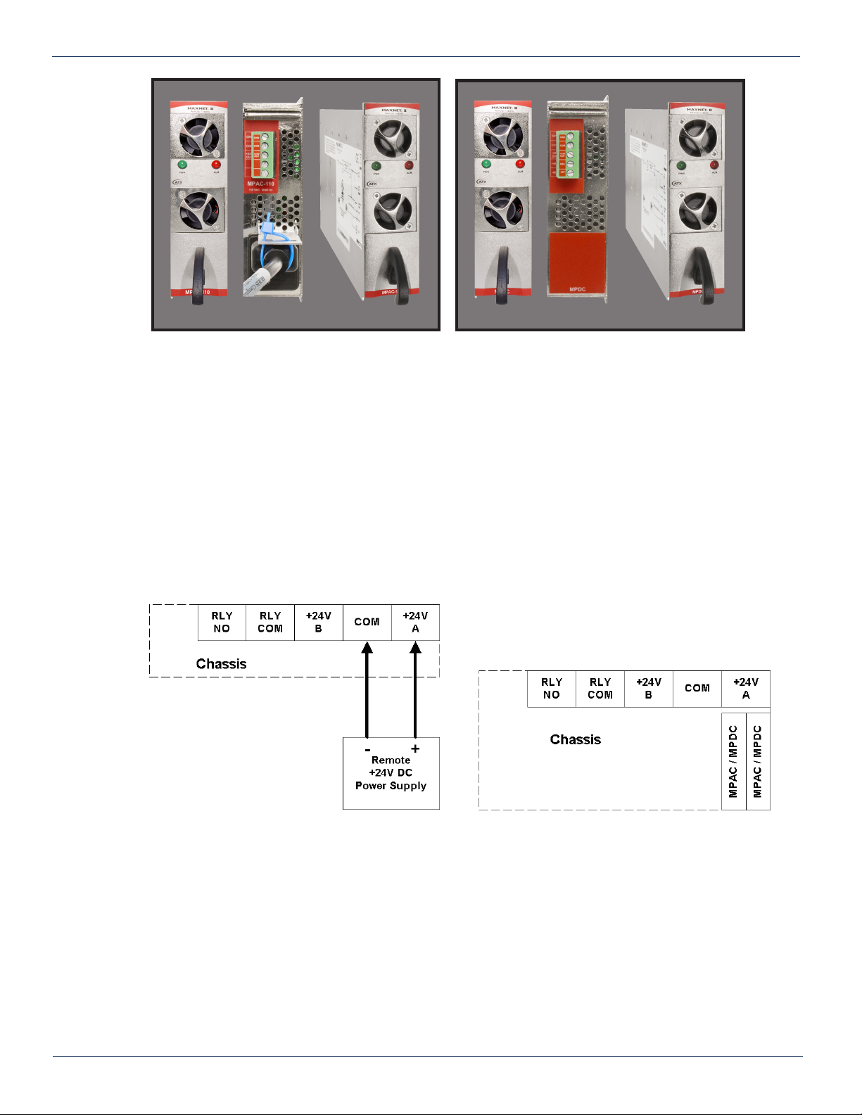
supply is an MPDC unit, using bus wire, connect –48 VDC into the terminal block on the back of the module following the
terminal block labelling (see below Table 3). A disconnect device is required between the -48 VDC supply and the MPDC
power supply.
To remove a power supply module from the chassis, gently lift the front handle and pull back on the module until it is clear
of the chassis guide slot. Power (AC or DC) should be disconnected from the module before removing for replacement or
service. This is accomplished by removing the AC IEC plug for the MPAC unit and the terminal block for the MPDC unit.
CHAPTER 1: PRODUCT DESCRIPTION CHAPTER 2: INSTALLATION
MAXNET®II – MPAC/MPDC Modular Power Supply – Installation & Operation Manual 2-1
Table #3: Rear Terminal Block Assignments
1
2
3
4
5
MPAC-110 /
MPAC-220 MPDC
+24V
OUT
COM
GND
+24V
OUT
COM
GND
RTN
-48V

CHAPTER 2: INSTALLATION
2-2 MAXNET®II – MPAC/MPDC Modular Power Supply – Installation & Operation Manual
2.3. DC Redundant Powering of Active MAXNET®II Chassis
If more than one power supply is connected to the chassis, the extra power supply acts as a redundant source of power.
Using internal logic within the module (MPAC uses diode steering, MPDC uses load sharing logic) if the main power supply
on the chassis fails, the other power supply becomes the active supplier to the +24 VDC chassis bus rail ensuring power is
always maintained to all active modules in the chassis.
2.4. Remote Powering of Additional Active MAXNET®II Chassis’
Both the MPAC and MPDC power supplies include the ability to remotely power additional MAXNET II chassis’ by connecting
bus wire to pin 2 (COM) and 3 (+24V) on the rear terminal block.
* In any of the examples above, be sure to refer to the next section for module power requirements. In any redundant
scenario, if a power supply fails, the load on any remaining power supply must not exceed 8 amps.
Figure #3: Front & Rear Panel Pictures
Figure #4: Remote Powering Figure #5: Redundant Powering
MPAC-110 / MPAC-220 MPDC

2.5. Module Power Requirements
2.6. LED Indicators
The MPAC and MPDC power supply module have two LED indicators: PWR and ALM.
a) The PWR (Power) LED veries, by lighting solid green, that the power supply is supplying 24 VDC powering to the
active MAXNET II chassis.
b) The ALM (Alarm) LED will ash red if there is a problem with the power supply or if any of its monitored functions
are beyond the specied limits.
__________________________________________________
1 If the ALM LED is ashing red at a slow rate of approximately 1s on-1s off, this is indicative of a communications failure between this module and
the chassis. See Troubleshooting section.
MAXNET®II – MPAC/MPDC Modular Power Supply – Installation & Operation Manual 2-3
CHAPTER 2: INSTALLATIONCHAPTER 2: INSTALLATION
Module
Max Current (A) 8 0.29 0.52 0.46 0.29 0.52 0.03 0.14 0.47 0.52
MPAC / MPDC
MPRX-8 /
MPRX-16
MPRX2-8
MPRXRR-16 /
MPRXRR-8
MPRX-DC /
MPRX2-DC
MPRX2-DC
MPRFA/B
QMP200
QMP1000
(< 22 dB Gain)
QMP1000
(> 22 dB Gain)
STATUS
FLASHING
RED1
SOLID
GREEN OFF
LED
PWR N/A 24V Power ON Check Power
Supply Module
ALM Module problem N/A Normal (PWR is
GREEN)
Table #4: LED Status Indications

2-4 MAXNET®II – MPAC/MPDC Modular Power Supply – Installation & Operation Manual
CHAPTER 2: INSTALLATION
This page left intentionally blank.

STATUS MONITORING
3. Status Monitoring
3.1. Chassis Interface Options
The Active MAXNET II product line can be monitored and controlled in either of two ways:
a) A free, web-based interface. This comes pre-installed on every chassis and provides a user friendly method of
conguring the administrative set-up and all monitoring and control. It is based on SNMP, but requires little knowledge
of SNMP. Any internet browser, such as Internet Explorer, is all the software that is required.
b) Any third-party SNMP Management software (e.g. www.castlerock.com, www.ndt-inc.com/SNMP/MIBrowser.html)
may be purchased separately. These suites tend to be expensive and not as user friendly as the web interface. The
web interface is also still required for administrative set-up. The 3rd party interface is recommended only for systems
that have an existing SNMP architecture. All MIBs (Management Information Bases) are freely downloadable from
the SCTE (www.scte.org/standards). ATX was able to support all modules using the SCTE standard HMS MIBs, so
no custom MIBs are required.
3.2. SCTEHMSMIBSoftwareDenitionofModule
The power supply module uses the headend power supply MIB to support voltage and current measurements of what it is
providing to the chassis’ backplane.
3.3. Web Interface
The MAXNET II chassis uses an integrated web page to supplement the SNMP management. All congurations of the
chassis (static IP address, trap/email recipients, rmware upgrades, etc) must be done through the web page. Simply use
any web browser (Internet Explorer, Firefox, etc) and enter the IP address of the chassis as the URL. Login as administrator
to modify conguration and have full read/write access to monitor and control modules. Login as Operator to have full read/
write access or login as observer to have read-only access. There is only one password per login level.
MAXNET®II – MPAC/MPDC Modular Power Supply – Installation & Operation Manual 3-1
CHAPTER 2: INSTALLATION CHAPTER 3: STATUS MONITORING

CHAPTER 3: STATUS MONITORING
3-2 MAXNET®II – MPAC/MPDC Modular Power Supply – Installation & Operation Manual
3.4. Updating Active Chassis Firmware
a) Login to web page interface of the chassis as an administrator.
b) Check software status page for current rev level. If an upgrade is necessary, proceed with next steps.
c) Go to Firmware tab.
d) Select ‘HTTP Server’ and verify it reads:
www.atxnetworks.com/rmware/MN2/image.bin
e) Select Upload and wait for conrmation page to appear. The chassis will perform an MD5 checksum on the
downloaded le to verify that no bit errors occurred.
f) If you are updating a version prior to 1.4.2, then the calculated MD5 Checksum will be displayed on the screen.
Contact Engineering at ATX to verify what this value should be (it will be the same for each chassis you upgrade
with a given revision).
g) If you are updating a chassis later than 1.4.2, then the checksum is veried automatically via a text le taken from
the ATX web server.
h) If md5checksum is veried, select Flash to memory. Donotashifit fails the MD5 checksum, as this could
permanently corrupt the memory.
i) Wait approximately 5 seconds, then disconnect the network cable and proceed to the next chassis. Leave the
recently updated chassis powered until it completes a reboot.
j) Optionally, the chassis may now be factory reset to restore all IP settings to factory defaults. Read the Factory Reset
section fully before doing this to know what data will be lost when doing this.
3.5. Factory Reset
A factory reset will restore the chassis to the state which it left the ATX production facility.
3.5.1. Parameters That will be Changed
IP address = 192.168.0.1
NetMask = 255.255.255.0
Gateway = 192.168.0.254
Passwords set to same text (but all lower case) as the login level. e.g. Operator password is operator.
All analogue and discrete alarm thresholds of modules will be reset to default values.
Alarm log will be cleared.
3.5.2. Purpose
Common reasons for requiring a factory reset are:
a) The chassis is unresponsive, or the IP address is not known
b) The Administrator password has been forgotten
c) The yellow COMM LED does not blink after the 2 minute boot cycle, even after a power cycle or press of the
RESET button
3.5.3. Method
If you are sure you want to factory reset, hold down the RESET button near the RJ45 port for at least 10 seconds. The yellow
COMM LED will be solid-on during this time, and once it turns off you can release the button and the reboot process will
begin.

STATUS MONITORING FEATURES
4. Status Monitoring Features
4.1. SNMP Parameters
MAXNET®II – MPAC/MPDC Modular Power Supply – Installation & Operation Manual 4-1
CHAPTER 4: STATUS MONITORING FEATURESCHAPTER 3: STATUS MONITORING
Table #5: Common Module SNMP Parameters
Display Name Description HMS MIB Variable
Model
ATX model number (note, in empty slots you can enter
passive, dual-passive, or empty to populate the overview
page with passive picture placeholders).
entPhysicalModelName
Description Description of the module. entPhysicalDescr
Name Indicates the slot of the chassis the module is in. entPhysicalName
Alias
Optional user dened eld - added to fth variable binding
of traps and emails
e.g. set this to “Node 69” for a given Receiver and any
alarms generated by this receiver will have “Node 69” in
the description. Otherwise, traps would only contain the IP
address of the chassis, the Model and Name (slot
number).
entPhysicalAlias
Manufacturer ATX entPhysicalMfgName
Asset I.D Optional user settable eld (suggestions: enter in a
custom serial number or purchase order # for tracking). entPhysicalAssetID
Serial No Module’s serial number. entPhysicalSerialNum
Hardware Rev Hardware rev of module. entPhysicalHardwareRev
Firmware Rev Firmware rev of module. entPhysicalFirmwareRev
Temperature [C] Module’s current heatsink temperature. heCommonTemperature
Alarm Detection Control
detectionEnabled: normal operation, with active alarms
detectionDisabled: used to temporarily disable alarms/
traps from this module
detectionEnabledandRegenerate: enter detectionEnabled
state while regenerating all alarm table entries
heCommonAlarmDetectionControl
Fan Unit Status Alarm status of the fan. heFanUnitAlarm
Display Name Description HMS MIB Variable
Voltage Out [Volt] Measured voltage supplied to the chassis from the MPAC
or MPDC hePsOutputVoltage
Current Out [mA] Current supplied to the 24V rail by the module hePsOutputCurrent
Power Out [Watts] Voltage Out * Current Out hePsOutputPower
Table #6: MPAC & MPDC SNMP Parameters

4.2. SNMP MIBs Required for MPAC & MPDC
4-2 MAXNET®II – MPAC/MPDC Modular Power Supply – Installation & Operation Manual
CHAPTER 4: STATUS MONITORING FEATURES
Table #7: SCTE HMS MIBs Required
HMS# SCTE#
SCTE-ROOT 028 36
SCTE-HMS-ROOTS 072 37
SCTE-HMS-HEADENDIDENT-MIB 114 38-11
SCTE-HMS-HE-COMMON-MIB 111 84-1
SCTE-HMS-PROPERTY-MIB 026 38-1
SCTE-HMS-HE-FAN-MIB 117 84-3
SCTE-HMS-HE-POWER-SUPPLY-MIB 116 84-2

MAINTENANCE & TROUBLESHOOTING
5. Maintenance & Troubleshooting
5.1. Maintenance
Daily, ensure that the Power LED’s are on for all of the modules and that there are no Alarm lights. Ensure that the yellow
‘COM’ LED near the rear RJ45 port is blinking.
Weekly, ensure that all module cooling fans are operational and unobstructed.
Monthly, vacuum all module cooling fans.
5.2. Troubleshooting
The following guide will help the operator to diagnose problems in active modules or chassis’. If none of the items in this
section are of help, please contact ATX for Technical Support.
5.2.1. Slow Flashing Red LED on Module Front
If any alarm LED on the front of the module is blinking at a rate of approximately 1 second ON, 1 second OFF, then this is
indicative of a slot addressing communications failure. RF and Optical functionality will likely still work, but the unit will have
no software monitoring or control during this time.
Try removing the module and replacing it. If this does not x the problem, then switch the module to a different slot in the
chassis. If the red LEDs return to normal operation, then the problem is in actual slot of the chassis and likely the connector
on the back rail is damaged. Contact ATX and report a defective chassis.
If this does not x the problem then contact ATX and report a defective module.
5.2.2. Chassis’ Yellow COM LED Not Blinking
It is normal for the round LED near the RJ45 port at the rear of the chassis to be solid ON or OFF during various states of
system boot-up. If the chassis has been powered up (solid green on the round “+24V” LED near the terminal block at the rear
of the chassis) for at least 2 minutes, then the yellow LED should be blinking to indicate the chassis software is running. If it
is not, a reboot is necessary.
If the chassis can be interrupted briey, then simply remove power to it by pulling all MPAC/MPDC modules out part-way.
If the chassis must remain live then try pressing the black RESET button near the RJ45 port. If this does not work, then the
communications module itself can be removed from the back of the chassis. Remove the two Phillips screws that hold the
module on, then pull it off and replace it. This will not interrupt the operation of the modules within the chassis.
If this still does not start the yellow LED blinking after boot-up, then a factory reset will be necessary (see Section 3.5.).
5.2.3. No Response From Chassis Over Network
Typically, this is a ‘subnet’ issue. In order for any device to see another device on the same network, they must be on the
same subnet. Consult your IT department for details of your network, but typically the subnet refers to the rst three of
the four octets in an IP address. E.g. if the computers in your network are given IP addresses of 192.168.10.1 through
192.168.10.250, then the subnet is the 192.168.10 part.
MAXNET®II – MPAC/MPDC Modular Power Supply – Installation & Operation Manual 5-1
CHAPTER 4: STATUS MONITORING FEATURES CHAPTER 5: MAINTENANCE & TROUBLESHOOTING

If the chassis is still not visible, it is possible the IP address of the chassis has been forgotten (see Factory Reset section),
the network connection is not good (see Ethernet Port section for LED diagnostics) or a network port is blocked or rewalled
(check with your IT department).
5.2.4. Some Modules Do Not Show Up On Web Page
If the chassis is visible on the web or through SNMP walks, but one or more installed modules is not, try removing and
replacing the module in a different slot. Verify that the green power LED is solid and the red LED is either off or blinking quickly
(approx. half second on, half second off). If the LED’s are not as stated, see the appropriate troubleshooting section.
5.2.5. Module Power LED Off or Intermittent
Check the ‘24V’ green LED on the rear of the chassis. If it is off, then the problem is that the chassis is not getting power.
See MPAC/MPDC troubleshooting section. If it is on or if other modules in the chassis are okay, the module itself is suspect.
Continue.
Remove the suspect module and trade slot positions with another functioning module.
a) If the suspect module is okay and the previously good module fails, contact ATX and report a defective chassis.
b) If the suspect module fails and the previously good module is okay, contact ATX and report that the suspect
module is defective.
5.2.6. MPAC/MPDC Not Powering Chassis
*Note that 220 VAC applied to an MPAC-110 will damage the module, but 110 VAC applied to an MPAC-220 will simply not
turn on.
a) Check the fuse continuity on the MPAC or MPDC module.
b) Verify that the 110 VAC / 220 VAC electrical outlet is active using a voltmeter and checking the circuit breaker. (In
the case of the MPDC insure that there is -48 VDC on the rear terminal block)
c) Verify that IEC power cord is properly inserted into the receptacle on the rear of the module and properly
connected to an 110 VAC / 220 VAC electrical outlet.
5-2 MAXNET®II – MPAC/MPDC Modular Power Supply – Installation & Operation Manual
CHAPTER 5: MAINTENANCE & TROUBLESHOOTING
Each MAXNET II chassis ships with a default IP of 192.168.0.1,
so the PC connected to it must have an IP address of 192.168.0.x
where x is not equal to 1. This is not generally the case, so it
must be forced.
To modify the PC’s IP in Windows, choose Start -> Settings ->
Network Connections -> Local Area Connection -> Properties
-> Internet Protocol (TCP/IP).
If the chassis IP is no longer at the default IP, modify the subnet
portions of these settings (IP address and Default Gateway) to
match.

5.2.7. Module Will Not Insert Fully Into Chassis
a) Remove the module and inspect it for damage or bent guide rails.
b) Inspect the chassis for bent metal or obstructions.
c) Be sure that the active module is inserted such that the left side is above an odd numbered slot and the right side
is above an even number slot.
d) Try the module in a different slot. Due to machinery tolerances, some modules may be more snug in some slots
than others. If the tolerances are unacceptable, contact ATX.
5.2.8. Temperature/Fan Fault Alarm on Any MAXNET®II Active Module
Check to see if the module fan is operating. If not replace with a new fan from ATX
(Fan Part #: MPFANA) using the below procedure.
5. Install replacement fan in the opposite order shown. Ensuring that:
a) The red and black wires are aligned.
b) The labelled side of the fan faces inward toward the module.
c) The wires do not bunch up behind the fan, interfering with fan rotation.
MAXNET®II – MPAC/MPDC Modular Power Supply – Installation & Operation Manual 5-3
CHAPTER 5: MAINTENANCE & TROUBLESHOOTING CHAPTER 5: MAINTENANCE & TROUBLESHOOTING
1. Remove two screws holding plate and fan
in place.
2. Remove fan cover and screws.
3. Pull out fan with tweezers. 4. Remove push-t power connections.

5-4 MAXNET®II – MPAC/MPDC Modular Power Supply – Installation & Operation Manual
CHAPTER 5: MAINTENANCE & TROUBLESHOOTING
This page left intentionally blank.
Other manuals for MAXNET II Platinum Series
1
Table of contents