ATYS MEDICAL SysToe User manual

User manual –SYSTOE 14 168 Rev. G Page 0/1
14168 G SysToe, user’s manual
Modif.
Rév.
Date
03 600
A
March 2, 2009
Initial release
03 670
B
May 15th, 2009
Upgrade
03 887
C
February, 10th 2010
Update for Canada regulation
Atys medical > Atys
Photos updates
Include of mode SEMI-AUTO
03 915
D
April, 1st 2010
Additional pictures for small toe
examination
04 090
E
7/02/2011
Publication date is added
CE mark is added
Page number corrected
04 321
F
27/01/2012
CEM tables
04 335
G
28/08/2012
Software version 23a
APPROBATION
Quality
R&D Atys
Sales

User manual - SYSTOE 14 168 Rev. G Page 1/38
SysToe
User’s manual
April 27, 2012
14 168 Rev.G
Atys SARL
17, parc d’Arbora
69510 Soucieu en Jarrest, France
Tel: +33 4 78 05 69 69, Fax: +33 4 78 05 69 60
atys@atysmedical.com

User manual –SYSTOE 14 168 Rev. G Page 2/38
Contents
1Read first...................................................................................................... 4
1.1 Operator .............................................................................................4
1.2 Storage environment........................................................................... 4
1.3 Operating environment........................................................................ 4
1.4 Maintenance and service....................................................................5
1.5 Safety requirements for PC-USB connection....................................... 5
1.6 Sensor and cuffs................................................................................. 5
1.7 Electrical safety................................................................................... 6
1.8 Environmental protection ....................................................................6
2Intended use................................................................................................. 6
3Principle of operation.................................................................................... 6
3.1 Introduction......................................................................................... 6
3.2 Photo plethysmography (PPG) sensor................................................7
4Main features................................................................................................ 7
5Applied parts ................................................................................................ 7
6Component set-up........................................................................................ 8
6.1 Unpacking...........................................................................................8
6.2 Main components................................................................................ 8
6.3 Preparation for use ............................................................................. 8
6.4 Side panel...........................................................................................9
6.5 Tubing set...........................................................................................9
6.6 Cuffs................................................................................................... 9
6.6.1 Sensor cuff..................................................................................... 9
6.6.2 Occlusion cuff ................................................................................ 9
6.7 Safety Symbols................................................................................. 10
6.8 Device labels .................................................................................... 10
6.9 Layout and displayed symbols .......................................................... 11
7Management of the battery......................................................................... 12
8A measurement step by step ...................................................................... 13
8.1 Patient preparation............................................................................ 13
8.2 Occlusion cuff................................................................................... 13
8.3 Double-sided ring tape...................................................................... 13
8.4 Sensor and its cuff............................................................................ 14
8.4.1 Normal toe ................................................................................... 14
8.4.2 Short toe...................................................................................... 15
8.5 Acquisition screen............................................................................. 15
8.5.1 MODE: selection of automatic or semi-automatic mode ............... 15
8.5.2 BRA.P: brachial pressure input .................................................... 15
8.6 START: start the measurement......................................................... 16
8.7 Display of the systolic pressure and TBI............................................ 18
8.8 Input of the patient data.................................................................... 19
9Configuration menus................................................................................... 20
9.1 Main menu........................................................................................ 20
9.2 Patient File........................................................................................ 20
9.2.1 Name........................................................................................... 20
9.2.2 Birth date ..................................................................................... 21
9.2.3 Sex .............................................................................................. 21
9.3 Archive.............................................................................................. 21

User manual –SYSTOE 14 168 Rev. G Page 3/38
9.3.1 Display the archive list and open an archive................................. 21
9.3.2 Review the content of an archive.................................................. 22
9.4 Configuration of the export mode...................................................... 22
9.5 Exam parameters.............................................................................. 23
9.5.1 Occlusion pressure ...................................................................... 23
9.5.2 Occlusion time ............................................................................. 23
9.5.3 Emptying time.............................................................................. 23
9.5.4 TBI configuration.......................................................................... 23
9.6 Device parameters............................................................................ 24
9.6.1 Date and time............................................................................... 24
9.6.2 Language..................................................................................... 24
9.6.3 User............................................................................................. 24
9.6.4 Shut down time............................................................................ 24
9.6.5 Device information ....................................................................... 24
10 Error messages.......................................................................................... 25
11 Examination export via USB ....................................................................... 26
12 Powering off the device .............................................................................. 26
13 Cleaning..................................................................................................... 27
13.1 Sensor and cuff................................................................................. 27
13.2 Console ............................................................................................ 27
14 Service....................................................................................................... 28
14.1 After sales service............................................................................. 28
14.2 Spare parts and accessories............................................................. 28
14.3 Replacing the battery........................................................................ 29
14.4 Troubleshooting................................................................................ 30
14.4.1 Main menu.............................................................................. 30
14.4.2 Control of the battery charge and temperature ........................ 30
14.4.3 Control of the sensor (photo detector) ..................................... 30
14.4.4 Control of the occlusion cuff leakage....................................... 31
14.4.5 Control of the sensor cuff leakage........................................... 31
14.4.6 Control of the pressure sensor calibration ............................... 31
14.4.7 Calibration............................................................................... 32
15 Regulations ................................................................................................ 33
16 Technical data............................................................................................ 33
16.1 Electrical characteristics.................................................................... 33
16.2 Physical specifications...................................................................... 33
16.3 Pressure sensor................................................................................ 33
16.4 PPG Sensor...................................................................................... 33
17 Standard compliance.................................................................................. 34
17.1 Safety............................................................................................... 34
17.2 Quality management......................................................................... 34
17.3 Software development ...................................................................... 34
17.4 Usability............................................................................................ 34
17.5 Risk management............................................................................. 34
17.6 Electro Magnetic Compatibility.......................................................... 34

User manual –SYSTOE 14 168 Rev. G Page 4/38
1 Read first
1.1 Operator
The SysToe performs properly only when operated and maintained as
specified in this manual.
It is the responsibility of the operator to use the SysToe in accordance
with the user’s manual, the warnings and the labels.
The SysToe must be used by or on the order of physician.
1.2 Storage environment
For transport and storage, the device must be placed in its original
packing. Cautions to be applied for the transport and the storage are
labeled on the box.
Storage: 10-40°C, 10-80% Hr.
If you do not have the original packing materials, please contact your
Atys’ dealer.
Do not use the SysToe if the packing is damaged
1.3 Operating environment
Climatic environment
Do not use the device outside the specified environment.
To prevent fire and electrical hazards, keep the SysToe out of rain, water
and humidity. If the system does come in contact with liquid, shut the
system down and contact your Atys’ service representative.
Operating: 15-25°C, 10-80% Hr.
Power supply
Universal medical grade AC-DC converter, class II, 9Vdc.
Use only the power supply supplied by Atys.
Electro-magnetic compatibility (EMC)
For best product performance and measurement accuracy, use only
accessories supplied by Atys. Use accessories according to the
manufacturer’s directions for use and your facility’s standards. The use of
accessories, sensors, and cables other than those specified may result in
increased emission and/or decreased immunity of the SysToe.
The SysToe shall not be used in home environment

User manual –SYSTOE 14 168 Rev. G Page 5/38
1.4 Maintenance and service
The SysToe performs properly only when operated and maintained as
specified in this manual.
It is the responsibility of the operator to use the SysToe in accordance
with the user’s manual, the warnings and the labels.
If the SysToe is found defective, it should not be used. The SysToe
should not be used if any parts are missing or are damaged. Parts that
are visibly broken, worn out, warped or contaminated must be replaced.
No components should be replaced with parts from any other
manufacturer. If the customer suspects a part may be defective, it is the
customer’s responsibility to contact Atys or Atys’ representative.
The SysToe should only be repaired by technicians authorized by Atys.
No components should be replaced with parts from any other
manufacturer. If the customer suspects a part may be defective, it is the
customer’s responsibility to contact Atys or Atys representative.
The SysToe should only be repaired by technicians authorized by Atys.
No modification of this equipment is allowed
1.5 Safety requirements for PC-USB connection
Commercial associated computer shall be in compliance with IEC60601-
1 or with the standards applicable to the PC.
In the case where it is not in compliance with IEC60601-1,
the computer:
-- shall be placed outside the patient area,
- leakage current must be verified for the whole system following IEC
60601-1 standard.
To be outside the patient area, minimum distances of 1.5 m to the side,
2.5 m above (IEC countries) or 1.83 m to the side and 2.29 m above (UL
countries) are required.
1.6 Sensor and cuffs
Never use the sensor or the cuffs on skin surfaces with recent
wounds/operative cuts. Never allow the transducer to come in contact
with body fluid.
The sensor and cuffs must be disinfected between patients in order to
prevent cross contamination.
Use all cleaning and disinfection procedures applicable to your
institution.
The sensor and cuffs are fragile.
Be very careful during their use and cleaning.

User manual –SYSTOE 14 168 Rev. G Page 6/38
1.7 Electrical safety
To avoid the risk of electrical shock, do not remove the covers of the
charger.
To avoid the risk of electrical shock, contact a qualified service
representative for service.
Before use, control the sensor and its cable for visible damages. Never
use the sensor if cracks or other damages are visible.
Disconnection from the main supply: disconnect the 2 poles
simultaneously: unplug the charger.
Do not position device so that it is difficult to disconnect from the mains.
In case of breakdown of the SysToe, please contact your Atys dealer.
1.8 Environmental protection
Do not wasp the SysToe and its accessories. They can be partially
recovered and re-used.
The wasting of the package and the SysToe must be performed
according the national regulations.
2 Intended use
The SysToe is designed to measure the toe or the digit systolic pressure in
a non-invasively way in order to assess peripheral vascular disease. The
SysToe must be used in hospitals, physician office or medical facilities.
3 Principle of operation
3.1 Introduction
The SysToe inflates the occlusion cuff up to the preset occlusion pressure.
Then, it deflates the occlusion cuff slowly until the pressure in the cuff
reaches 10 mmHg.
The pressure in the cuff and the PPG (Photo PlethysmoGraphy) signal are
recorded during deflation. The pressure at the time of resumption of arterial
inflow is the systolic pressure.
Resumption of arterial inflow is detected by the PPG sensor.

User manual –SYSTOE 14 168 Rev. G Page 7/38
3.2 Photo plethysmography (PPG) sensor
The PPG sensor is composed of an emitter and a photodetector (Infrared).
The interaction of light with biological tissue is complex and includes the
optical processes of multiple scattering, absorption, reflection, transmission
and fluorescence.
Light received by the photodetector is affected by the blood volume, blood
vessel wall movement and the orientation of red blood cells (RBC).
The pulsatile component of the PPG waveform (‘AC’ component) has its
fundamental frequency depending on heart rate.
This AC component is superimposed onto a large quasi-continuous
component (‘DC’ component) that relates to the tissues and to the average
blood volume. This DC component varies slowly due to respiration,
vasomotor activity and vasoconstrictor waves, Traube Hering Mayer (THM)
waves and thermoregulation.
4 Main features
The SysToe is a portable, lightweight instrument which measures the
systolic pressure in the digit in a non-invasive way.
The principal features of the SysToe are the followings:
Automatic inflation and deflation the cuffs.
Display the PPG sensor signal and the systolic pressure (SYS) in the
toe or digit.
Display the TBI (Toe Brachial Index or Finger Brachial Index) once
the user inputs the systolic brachial pressure.
Can store up to 32 examinations.
Enables data to be transmitted to a computer via the USB port for
their storage and the printout of examination reports.
5 Applied parts
Infrared sensor.
Infrared sensor

User manual –SYSTOE 14 168 Rev. G Page 8/38
6 Component set-up
6.1 Unpacking
Atys ships the system in a box specially designed for the SysToe. It is
essential to ship the equipment using the original packing materials.
6.2 Main components
Confirm all components below are present. If any component is missing or
damaged, contact Atys or its representative.
6.3 Preparation for use
The device is shipped ready for use. All the elements (the cuffs and the
sensor) are connected to the SysToe.
To use the PC software, you will have to connect the USB cable.
For packing or moving of the device, you can place the device with the
connected sensor and cuffs in the packing box.
Box including the
PC software
& the user’s manual
Battery
charger
er
Occlusion cuff
USB cable
for PC connection
Packing
box
ox
Main
unit
Tubing set
for the two cuffs
PPG sensor cuff
with sensor

User manual –SYSTOE 14 168 Rev. G Page 9/38
6.4 Side panel
RESET: To stop the system in case of emergency.
Could damage the system: do not use to stop the system.
6.5 Tubing set
The tubing set is composed of 2 linked tubes that make the connection
between the cuffs and the SysToe and one half-tube for the sensor cable.
6.6 Cuffs
SysToe side
Toe side
6.6.1 Sensor cuff
The sensor cuff includes a tube that is fitted with a female connector.
This female connector is connected through the tubing set to the device.
6.6.2 Occlusion cuff
The occlusion cuff includes a tube that is fitted with a male connector.
This male connector is connected through the tubing set to the device.
OCCL.
OCCL.
SENSOR
SENSOR
Occlusion cuff
Buzzer
Sensor
Pressure sensor
Emergency stop
Battery charging indicator
Flashing: when charging
Charger connector
USB

User manual –SYSTOE 14 168 Rev. G Page 10/38
6.7 Safety Symbols
ROHS
Do not wasp. To be partially recover and re-used.
USB input/output signal
IEC60417-5333
Sensor protection type is BF.
IEC60417-5031
DC charger input
IEC60417-5109
Do not use in a private home environment
ISO7000-1641
Consult operating instructions
CE MARK
IEC60417-5134
Electrostatic sensitive connector
ISO7000-2498
Serial number.
IEC60417-5448
Data Input and Output
IEC60417-5546
Battery load indicator
ISO7000-434
Consult accompanying documents.
IEC60417-5009
standby
6.8 Device labels
RESET
Halts the system in case of emergency.
Can damage the system: do not use to stop the system.
MENU
Access to menu
ZOOM
Zoom curves after acquisition
SYS
Systolic pressure in the toe or finger
TBI
Toe (or Finger) brachial index = Toe (or Finger) systolic
pressure/ brachial systolic pressure or
SENSOR
Air flow connector to sensor cuff
OCCL.
Air flow connector to occlusion cuff

User manual –SYSTOE 14 168 Rev. G Page 11/38
6.9 Layout and displayed symbols
Battery power indicator
Occlusion pressure
Slow scrolling
Fast scrolling
Power
ON/OFF
Function Keys
F1/F2/F3
Touches
T1T9
Touche
ENTER

User manual –SYSTOE 14 168 Rev. G Page 12/38
7 Management of the battery
Replace the battery pack annually or when its capacity is noticeably
diminished.
The battery has been designed for a certain number of charge/discharge
cycles.
The battery must be charged only when a specific message is displayed.
Hereafter is an example of this kind of messages.
When the SysToe is switched off or on, a message is displayed in order to
let you know if you have to connect the charger or not.
If the battery is low and if you have to do a measurement you can work
with the SysToe connected to the charger.
Once the SysToe is connected to the charger, it must remain connected to
the charger for 5 hours in order to charge fully the battery.
To charge the battery, plug the charger to the charger connector on the
side of the SysToe.
The yellow CHARGING indicator flashes during charging.
The SysToe uses a Nickel Medal Hydride (NiMH) battery pack. The
system charges a fully depleted battery in 5 hours.
Do not always use the SysToe connected to the charger.
User manual –SYSTOE 14 168 Rev. G Page 13/38
8 A measurement step by step
8.1 Patient preparation
Position the patient appropriately on his/her back on the examination table.
You may elevate the patient’s head (the head only not the back) with
pillows for greater comfort. The patient’s feet should be resting comfortably
on the examination table.
For accurate exam results, the patient must be warm. The room
temperature should be between 22°C and 25 °C. If the patient’s toes are
cold, it is advised to warm them up. The skin temperature of the toe for low
toes blood flow volume must be higher than 27°C.
The patient must remain relaxed throughout the exam. The user should
remind him/her to remain still and refrain from talking.
8.2 Occlusion cuff
Wrap the occlusion cuff at the base of the toe so that the pipe goes
downwards. For the big toe, studies have shown that the width of the cuff
must be at least 25 mm otherwise the measured pression is overestilated.
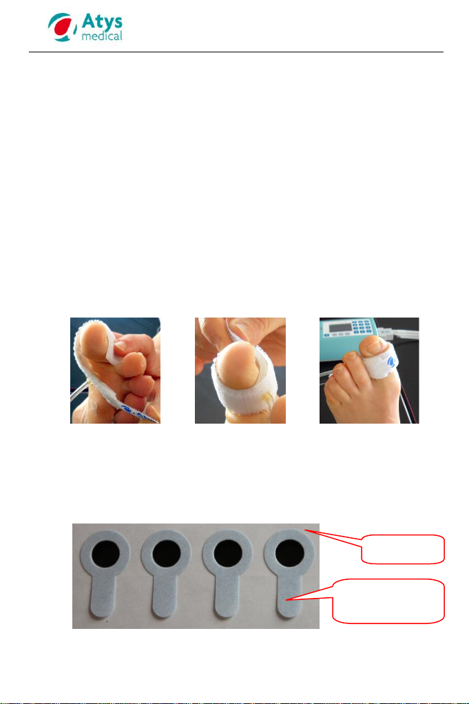
8.3 Double-sided ring tape
For a better contact of the sensor with the skin during the measurement,
stick a two-sided ring adhesive on the sensor before positioning the sensor
on the toe. It is compulsory to stick the sensor otherwise the quality of the
measurement is not warrantied.
The double sided tape has been designed by Atys especially for the
SysToe. It must be supplied only by Atys.
Support
Tongue of the
protective layer

User manual –SYSTOE 14 168 Rev. G Page 14/38
Remove one double sided tape from its support pulling the tongue.
Apply the sticky part of the ring tape on the sensor.
8.4 Sensor and its cuff
Then, there are two cases according to the length of the toe: Normal toe
(§8.4.1) and Short toe (§ 8.4.2)
8.4.1 Normal toe
Stick the sensor on the extremity of the toe and fasten the sensor cuff.
The whole surface of the sensor must be well in contact with the toe.
The sensor must be placed on the back of the toe and not on the nail.
The sensor and its cuff must be positioned so that the sensor wire and the
cuff tube go downwards (as shown on the picture below).
Both cuffs must fit the toe but they must not be too tight. They must not
induce any residual pressure on the blood vessels.
The adhesive ring must not cover the
infrared cells
Remove the protective layer pulling
the tongue off
Press firmly all over the ring to make sure
it is well stuck on the sensor

User manual –SYSTOE 14 168 Rev. G Page 15/38
8.4.2 Short toe
The toe is too short to accommodate both cuffs. The sensor cuff is not
placed on the toe. Remove the sensor from its cuff.
Stick a two-sided adhesive on the sensor and stick the sensor on the toe.
8.5 Acquisition screen
Once the SysToe is switched on, the acquisition screen is displayed.
MODE: Selection of AUTO (normal toe)
or SEMI-AUTO (short toe)
BRA.P: Input of the brachial pressure
(only if TBI is needed).
START:START the measurement
: Access main menu
8.5.1 MODE: selection of automatic or semi-automatic mode
When the toe is long enough to accommodate both cuffs (occlusion and
sensor cuffs), press on MODE to select MODE AUTO.
When the toe is too short to accommodate both cuffs, remove the sensor
from its cuff (see § 8.4.2) and press on MODE to select MODE SEMI-
AUTO.
8.5.2 BRA.P: brachial pressure input
Input the value with the numeric pad.
The arm pressure is not measured by the
SysToe.
DEFLT: Load last programmed value
CLEAR: Erase value
RET.: Save & return to the acquisition
screen

User manual –SYSTOE 14 168 Rev. G Page 16/38
8.6 START: start the measurement
From the acquisition screen, press on START to start an examination.
If current mode is AUTO (regular toe), cuffs are automatically inflated
once the user has pressed on START.
If current mode is SEMI-AUTO (short toe), the user needs to press
on the sensor to start the examination. The pressure on the sensor
should be kept as long as the message “Keep press until bip” is
displayed (see hereafter description table with illustrations). The user
needs to
press rather hard to get a proper emptying of the toe pulp.
Toe length
REGULAR TOE
SHORT TOE
Examination
mode
AUTO (see §8.3)
SEMI-AUTO (see §8.4.2)
Occlusion cuff
positioning
YES
YES
Sensor cuff
positioning
YES
NO
(Remove the cuff)
Sensor
positioning
YES, with double-sided tape
YES, with double-sided tape
Before START
Before START
Whatever the mode (AUTO or SEMI-AUTO), the display of
the SysToe looks like one of these two displays.

User manual –SYSTOE 14 168 Rev. G Page 17/38
START
Press on START to start the measurement
After START
AUTOMATIC PUMPING
Press quite strongly on the
sensor as shown below to
start the inflation of the
cuffs.
Keep pressing on the
sensor until the following
message is no longer
displayed “Keep press until
BIP”.
When the pressure on the
sensor must be released,
the SysToe emits a
sequence of beeps.
Once the occlusion pressure is reached, then the pressure in the occlusion
cuff decreases slowly. The display of the SysToe is the following ones.
The pressure in the occlusion cuff is
higher than the systolic pressure
The pressure in the occlusion cuff is
lower than the systolic pressure

User manual –SYSTOE 14 168 Rev. G Page 18/38
The examination automatically stops when the pressure reaches 10
mmHg. But, if the backflow is clear, it is possible to stop the exam before.
The return of the blood flow takes place when the pressure in the cuff is
lower than the systolic pressure. This is shown on the SysToe by a clear
and confirmed increase of the sensor signal.
STOP: Manual STOP of the examination
procedure.
Use this function to stop the examination
procedure before the occlusion cuff is fully
deflated if you have noticed the backflow
return or if you are under the impression that
something is wrong.
8.7 Display of the systolic pressure and TBI
Once the examination is over, the following screen is displayed.
The SysToe places automatically the vertical cursor. It must be placed at
the foot of the increase of the sensor signal (as on the left hand display).
If it is the case, the user has to press on VALID.
If it is not the case, the user has to move the vertical cursor to its proper
position with the horizontal arrows and then press on VALID
.
VALID: validation of the vertical cursor position and go to the result page.
: Displacement of the vertical cursor.
: Change the displacement speed for cursor scrolling
: Fast scrolling
: Zoom IN/OUT
Vertical cursor

User manual –SYSTOE 14 168 Rev. G Page 19/38
Once the user has validated the cursor position the following results screen
is displayed.
TOE: Toe or finger systolic pressure
BRA.: Brachial systolic pressure
TBI: Toe or finger Brachial Index
BACK: To go to the previous screen
NEW: To go to the acquisition screen to
perform a new measurement
VALID: To save the measurement in the
internal memory
To input the brachial pressure
8.8 Input of the patient data
Before saving the measurement in the internal memory of the SysToe, it is
advised to input some patient data in order to:
Make easy the identification of the measurement
Take advantage of the report generator
It is advised to input the patient name, the type and the side of the digit
(toe or finger)
The VALID key on the results screen allows the saving of the
measurement in the SysToe memory. But before, the three following
screens are displayed one after the other to give the opportunity to the
user to input some specific data about the patient.
When there is a figure or a symbol in front of a line of a menu, it means
that if you press on the alphanumeric pad on the same figure or symbol,
you will adjust or display the corresponding field.
BACK : To go to the previous display
NEW: To go to the acquisition screen in
order to perform a new
measurement
VALID: To validate the input data
SAVE: To save the current measurement and go to the acquisition
screen in order toperform a new measurement.
Table of contents


