Auber Instruments DSPR-5 User manual

AuberInstruments,Inc. www.auberins.com
Copyright2007‐2023,AuberInstruments.AllRightsReserved.
Nopartofthismanualshallbecopied,reproduced,ortransmittedinanywaywithouttheprior,writtenconsentofAuberInstruments.Auber
Instrumentsretainstheexclusiverightstoallinformationincludedinthisdocument.
DSPR-5 User Manual
Ver0.9(June6,2023)
1. Specifications
Inputsensortype
Thermocouple:K
RTD(ResistanceTemperatureDetector):PT100,PT1000
NTCThermistor(NegativeTemperatureCoefficient):50Kat25°C
Accuracy ±0.2%offullscale
Sensorinputrange
Thermocouple TypeK:0
°
F~2372°F,‐17
°
C~1300°C
RTDs:0°F~932°F,‐17°C~500°C
NTCThermistor50K:32°F~392°F,0°C~200°C
Responsetime ≤0.5s
Displayresolution 1°Cor°F
Controlmode Automatic(PID,ON/OFF),manual
Timerrange(HH:MM) 00H00Mto99H59M
Mainoutputvoltage 12VDCforsolid‐staterelay
Powersupply 85V~260VAC/50~60Hz
Powerconsumption ≤5Watt
Workingambient
temperature 32°F~122°F,0°C~50°C
Dimensions 48x48x120mm(WxHxD)
Mountingcutout 45x45mm
2. Front Panel
1
2
3
6
5
4
Figure1.FrontpanelofDSPR‐5.
Descriptions
1.PVwindow.Displaytheprobereading(andtimerifthetimerfunctionisenabled).
2.SVwindow.Displaythesetvalueineithertemperatureorinpowerpercentage.

AuberInstruments,Inc. www.auberins.com
Page2of6
3.EditingIndicator.Ifthisdotlightup,thesetvaluehasbeenchangedbytheuserandhasnotbeen
saved.
4.Rotaryknob.Rotatetoadjustvalues.Pressdowntoconfirmselectionortoaccessmenus.
5.OUTindicator.Toindicatetheoutputstatusfromthecontroller.
6.A‐Mindicator.Auto/manualindicator.TheyellowLEDturnsoninmanualcontrolmode.
3. Terminal Assignment
DSPR‐5
1
2
3
4
5
6
7
8
9
10
13 14
+
‐
Ou tp ut
(toSSR)
DC12V
Po werIn put
AC85V–260V
+
‐
TCK
PT1K/NTC50K
PT100
Figure2.TerminalassignmentofDSPR‐5.
4. Getting Started
Beforeyouconnectthepowertothiscontrollerorinstallittoacontrolpanel,pleasereadthemanual
thoroughlytounderstandhowthecontrollerworks.Youshouldunderstandthefollowingbeforeyou
startusingthecontroller:
1. Identifythecorrectterminalsforconnectingthepowersupply,thetemperaturesensor,the
outputtodriveexternalsolid‐staterelays.
2. Understandwhatinformationwillbeconveyedbyeachofthedisplaywindowandeach
indicator.
3. Familiarwithhowtochangethesettemperatureorpowerpercentageonthecontroller.
4. Familiarwithhowtoaccessthemenusandunderstandwhateachparameterdoes.
5. Connecting the Controller
5.1. Power Input
ThecontrollerrequiresanACpowersupplyineither120VACor230VAC.TheinputACpower
shouldbeconnectedto#9and#10.
5.2. Sensor Input
Thiscontrollercanacceptafewcommonlyusedtemperaturesensors:typeKthermocouple,
PT1000RTD,NTC50Kohmthermistor,andPT100RTD.

AuberInstruments,Inc. www.auberins.com
Page3of6
TypeK:connectorthepositiveleadto#4andthenegativeleadto#5.
PT1000RTD:connectsensorleadsto#4and#5.Nopolarity.
NTC50Kohmthermistor:connectsensorleadsto#4and#5.Nopolarity.
PT100RTD:connecttwowiresofthesamecolorto#4and#5;connecttheotherlead
to#6.
Theinputsensortypeonthecontroller,parameter“Sn”(Sn),mustbesettomatchthe
actualsensortypethatisconnected.Byfactorydefault,thecontrollerissettoreadytypeK
thermocouple(K).Pleaseseesection8.2fordetails.
5.3. Control Output
Theoutputsignalfromthiscontrollerisa12VDCsignal,whichcanbeusedtodrivesolid‐state
relays.TheoutputstatusisindicatedbythegreenOUTLEDonthefrontpanel.
6. Changing the Set Value
ThedefaultSetValue(SV)is100°F.TochangetheSetValue:
1. TurntheknobandaflashingdotwillappearonthelowerrightcorneroftheSVwindow.
2. TurntheknobtoclockwisetoincreasetheSV;turntheknowcounter‐clockwisetodecrease
theSV.OncegettothedesiredSV,pressdowntheknobtosavethenewvalue.Otherwise,the
oldSVwillberestored.
3. OncethenewSVisconfirmed,thedotinthelowerrightcornerwillgoaway.
4. TheSVcanbechangedcontinuouslybetweenthetemperaturevalueandthepower
percentagevalue.Pleaseseethenextsectionfordetails.
5. IftheSVissettoapercentagevalue,thelowerwindowwillshowletter“P”ontheleft
window.TheA‐MLEDdiodeturnsontoindicatethatthecontrollerisworkinginmanual
controlmode.(Figure3)
7. Switching between Auto Mode and Manual Mode
OneofthemostconvenientfeaturesinDSPR‐5isthattheSVcanbechangedcontinuouslybetweena
temperaturevalue(0°Fto932°F)andapowerpercentagevalue(0%to100%),andthecorresponding
controlmodebetweenchangedaswellbetweentheAutoControlModeandtheManualControl
Mode.
Auto Control Mode
WhentheSVisatemperaturevalue,thecontrollerworksinautomaticcontrolmode,whichmeansthe
controllerwillautomaticallyadjusttheoutputpowertobringthetemperaturetothetargetvalue.The
lowerwindowwilljustshowanumberwithoutanyletter.TheyellowA‐Mindicatorshouldbeoff.
AuberInstruments,Inc. www.auberins.com
Page4of6
Manual Control Mode
WhentheSVissettoapercentagevalue,thecontrollerworksinmanualcontrolmode,whichmeans
thecontrollerwillsendthepowerpercentagedeterminedbytheuser.Thelowerwindowwillshow
letter“P”onthelefttoindicatortheSVisapercentagevalue.TheyellowA‐Mindicatorshouldbeon.
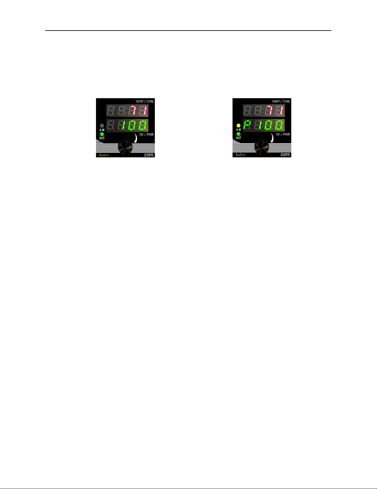
AutoControlMode ManualControlMode
Figure3.ComparethedifferencesofthedisplayonaDSPR‐5inAutoControlModewiththeSVsetat100°F(left)and
thecontrollerinManualControlModewiththeSVsetat100%output(right).
PleaseseethetwoimagesinFigure3,whichshowacontrollerinAutoModeontheleft,anda
controllerinManualModeontheright.ThecontrollerinManualModehastheA‐Mindicatorturning
onandtheletter“P”(P)inthelowerwindow.
ToswitchbetweenAutoModeandManualMode:
1. SimplyturntheknobtochangetheSVtoeitheratemperature(automode)orapercentage
value(manualmode).TheSVcanbechangedcontinuouslyfrom0%to100%to0°Fto932°F.
2. AstheSVvaluetransitsbetweenpercentagevalue“P100”andtemperaturevalue“0”degree,
thelowerwindowtoprompteither“TEMP”(temp)or“PCT”(Pct)brieflytoindicatethe
newSVwillbeatemperaturevalueorapercentagevalue.
3. WhentheSVissettoapercentagevalue,thelowerwindowwillshowletter“P”ontheleftand
theA‐Mindicatorwillturnon.
4. WhentheSVissettoatemperaturevalue,thelowerwindowwillonlyshowanumberandthe
A‐Mindicatorwillturnoff.
8. Access the Menu
Pressdowntheknobandholditfor2secondstobringupthemenu.Thetopwindowwillshow“goto”
(GOTO).Turntheknobtochangethelowerwindowto“CTRL”(CTRL)or“SYST”(SYST),thenpress
downtheknobshortlytoenternextlevelofmenu.Whenthecontrollerisinthemenusystem,ifthere
isnoactionfor30secondsfromtheuser,thecontrollerwillautomaticallyreturntothenormal
operatingmode.

AuberInstruments,Inc. www.auberins.com
Page5of6
8.1. Control Configuration (CTRL)
Table1.ParametersinCTRLmenu.
Name Symbol Description Range Default Details
P P Proportional
band
0~9999 20 Unitindegrees.Largerthevalue,widertheband,
weakeractionfromtheproportionalcontrol.
IfP=1,I=0,D=0,itisON/OFFcontrolmode.
I I Integraltime 0~9999 100 Unitinseconds.Largerthevalue,weaker/slowerthe
actionfromtheintegralcontrol.
D D Derivative
time
0~9999 10 Unitinseconds.Largerthevalue,strongertheaction
fromthederivativecontrol.
T T Controlcycle
time
2‐120 2 Unitinseconds.
Hy Hy Hysteresis
band
0~999 2 Hysteresisband.OnlyappliestotheON/OFFcontrol
mode(i.e.,whenP=1,I=0,D=0).
OUTL OUTL Outputlow‐
limit
0~100 0% Minimumoutputlevel.Onlyappliestoautocontrol
mode
OUTH OUTH Outputhigh‐
limit
0~100 100% Maximumoutputlevel.Onlyappliestoautocontrol
mode
AT AT Auto‐tuning N,Y N Startauto‐tuningPIDparameters.Onlyappliesto
autocontrolmode
TF TF Timer
function
OFF,ON OFF OFF:disablethetimerfunction
ON:enabletimerfunction
TIME TIME Timersetting 00:00~
99:59
01:00 TimerunitinHH:MM
EO EO Ending
output
OFF,ON OFF Weathertoenableoutputafterthecount‐down
timerhasbeenreached.
OFF:disableoutputattheendofthetimercount‐
down.
ON:enableoutputtheendofthetimercount‐down.
8.2. System Configuration (SYST)
Table2.ParametersinSYSTmenu.
Name Symbol Description Range Default Details
Sn Sn Inputsensor
type
K,PT1K,
P100,
N50K
PT1K K:typeKthermocouple;
PT1K:PT1000RTD;
P100:PT100RTD;
N50K:50KNTCthermistor.
Pb Pb Probeoffset ‐20~
+20
0 Addanoffsettothetemperatureinputsignalfrom
thesensor.
C‐F C-F Temperature
unit
°C,°F °F DisplaythetemperatureinCelsiusorinFahrenheit.
PMOD Pmod Output
signaltype
TP,BF TP TP:time‐proportional;
BF:burst‐firingmode.

AuberInstruments,Inc. www.auberins.com
Page6of6
MMOL MmOL Manual
modeopen‐
loop
Y,N N Enableoutputinopen‐loopsituation(sensorfailure
ornosensorisconnected).Onlyappliestomanual
mode.
N:disableoutputinopen‐loopsituation(i.e.,no
sensorisconnected).
Y:enableoutputinopen‐loopsituation.
mSV mSV Maximum
SetValue
0~2372 932 TheupperlimitoftemperatureSV.
VER VER Firmware
version
Firmwareversionnumber.Displayonly.
(Currentfirmwarever1.2.1)
RST rst Factoryreset N,Y N N:noaction.
Y:resetallparameterstofactorydefaultvalues.
9. Reset the Timer
ImportantNote:thisoperationisonlyavailabletosituations:
1)whenthetimerfunctionisenabled(i.e.,parameter“TF”issetto“on”)AND
2)whentheaccount‐downtimerhasbeentriggered(i.e.,afterthePVhasreachedtheSV).
Toresetthetimer,pressdowntheknobbriefly,thecontrollerwillshow“TRST”inthetopwindow
andshow“n”inthelowerwindow.Turntheknobtochangetheletterinthelowerwindowto“y”and
thenpressdowntheknobtoresetthetimer.
Timer Reset (“tRST”)
Name Symbol Description Range Default Note
TRST trst Timerreset N,Y N N:Noaction.
Y:resetthetimer.
(End)
AuberInstruments,Inc.
5755NorthPointParkway,Suite99,
Alpharetta,GA30022,USA.
www.auberins.com
E‐mail:[email protected]
Tel:770‐569‐8420
Copyright2007‐2023,AuberInstruments.AllRightsReserved.
Nopartofthismanualshallbecopied,reproduced,ortransmittedinanywaywithouttheprior,writtenconsentofAuberInstruments.Auber
Instrumentsretainstheexclusiverightstoallinformationincludedinthisdocument.
Table of contents


