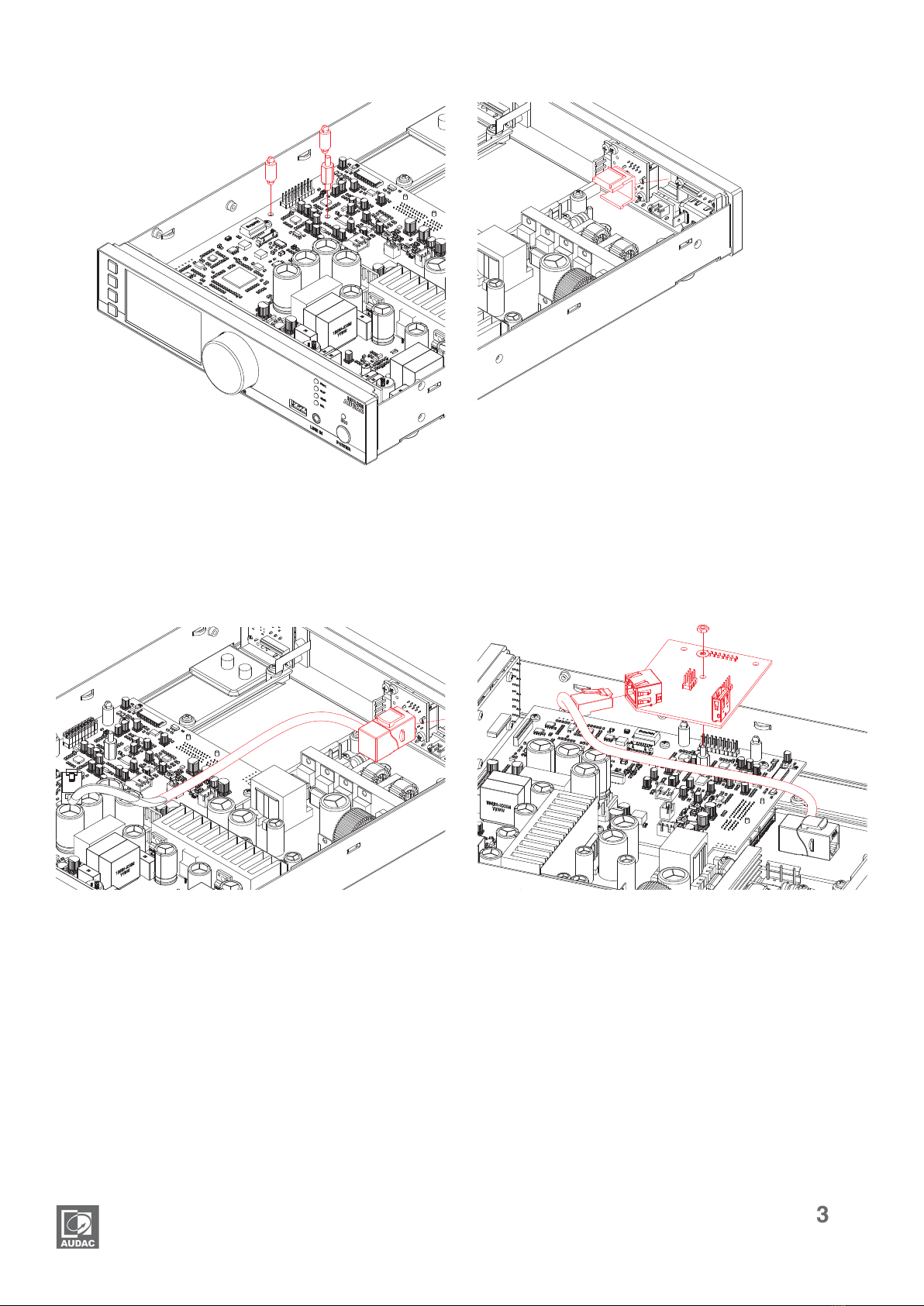
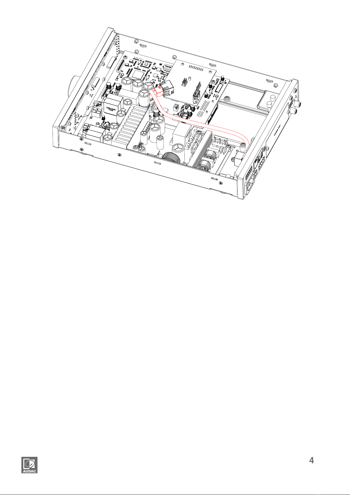
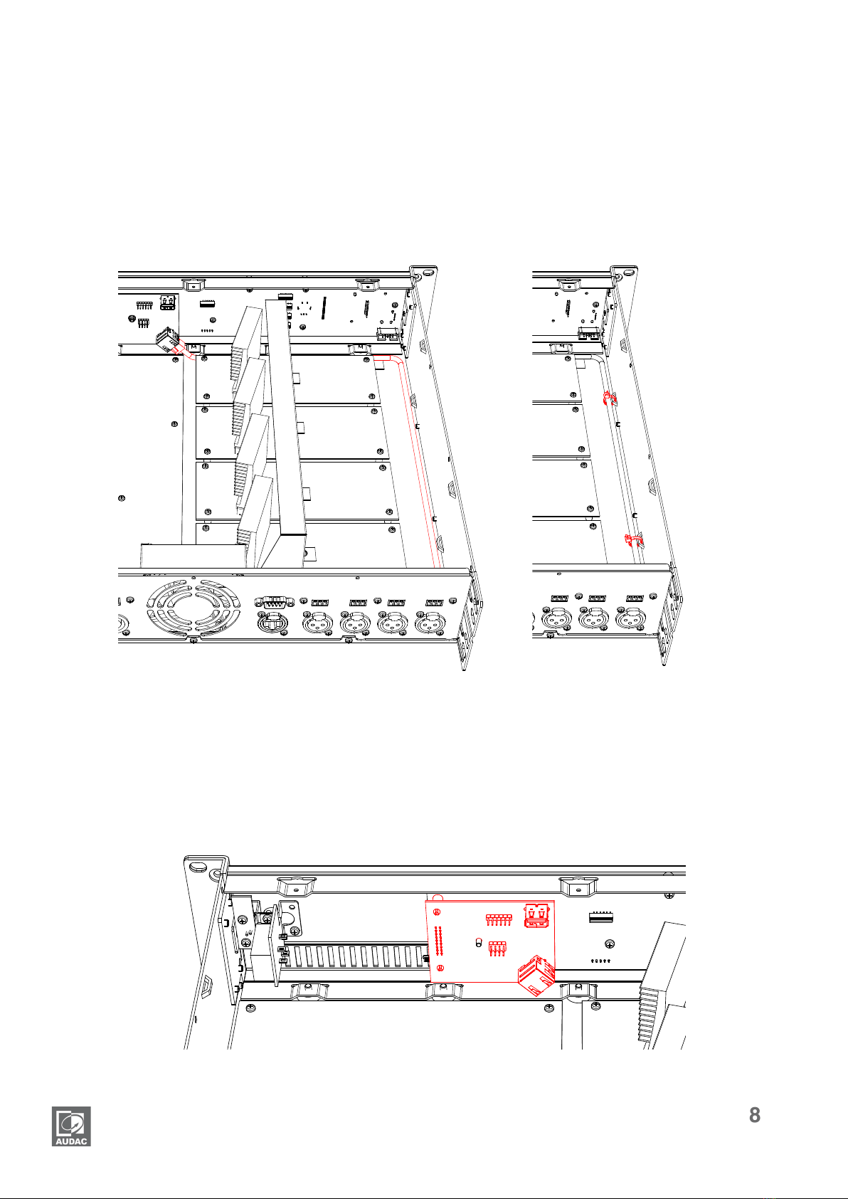
Step 8: Cable management
Use the included cable tie’s to lock the
network cable into place to avoid it moving
and touching the heatsinks.
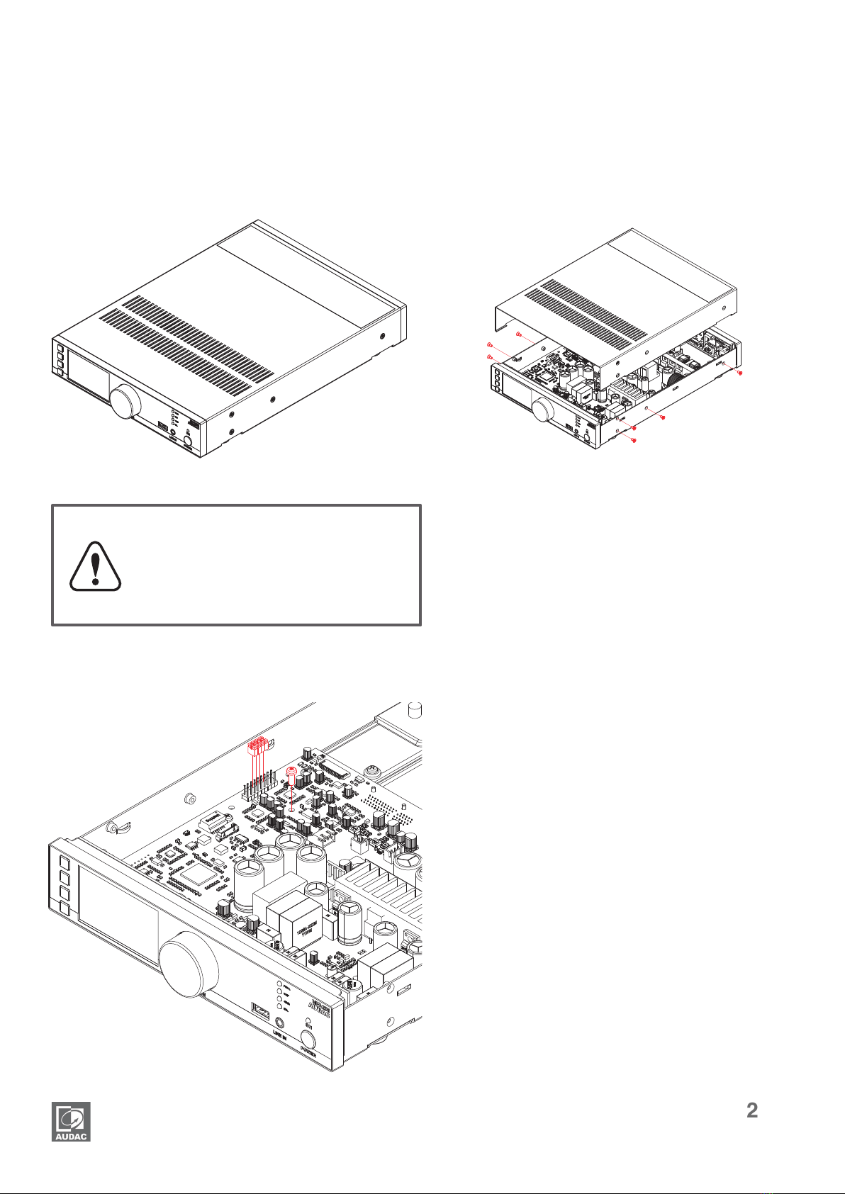
Double check whether all internal wires are
well connected and well positioned. After
all connections are successfully made, the
top cover of the amplier can be re-tted
and xed using the original screws.
Step 9: Up to date
To guarantee the correct functioning of
the amplier with the installed ANI Dante
network audio interface, Verify that current
MFA software is version 1.2.6 or higher.
The software version of your amplier
is shown on the front LCD display when
powering on the amplier. When it is not
Dante ready, you can update your amplier
over-the-air. Check for the latest rmware
update.
Result:
Your MFA is now equipped with a Dante network audio interface, allowing new networked audio
possibilities.
For more information about the functions, the connections or Dante in general, refer
to the quick start guide or Dante controller user guide.