AUDAC MTX48 User manual

MTX48/88
User Manual
www.audac.eu

2

3
Index
Introduction 5
MTX Block Diagram 6
Precautions 7
Safety requirements7
Caution servicing7
EC Declaration of Conformity7
Waste of Electrical and Electronic Equipment (WEEE) 8
Caution 8
Chapter 1: Pin connections and connectors 9
Connection standards 9
Wire up the system 11
Chapter 2: Front & rear panel 12
Front panel overview 12
Front panel functions 13
Functions overview 15
Rear panel overview 17
Chapter 3: MTX Quick start guide 20
Connecting the MTX 20
Configuring the MTX 21
Ready 22
Chapter 4: User interface & configuration 23
Open the user interface 23
Login screen 23
Main screen 24
Zone settings 25
Input selection 26
Configuration settings screen 27
Paging volume 28
Priority settings 29
System configuration 30
Mono / Stereo 31
Network settings 32
Password settings 33
Factory settings reset 34
iPhone + iPad 35

4
Chapter 5: Peripheral interfaces 36
Wall mounted control panels 37
MWX43/45 Basic wall panel 37
MWX65 All-in-one wall panel 39
WMI and WLI Wall Input units 40
MTX Wall Panel Connection possibilities 41
Paging 43
Peripheral connection limits 45
Chapter 6: Additional information 46
IP Basics 46
Updating the MTX 47
Technical specifications 48
Personal notes 49

5
Introduction
Multi-Zone Matrix
TheMTXisAUDAC’sseriesofverycostefficientaudiomatrixsystemsforawiderangeof
Multi-Zoneaudioapplications,offeringtwodifferentmodelswiththesamefeaturesand
possibilities,butwithdifferentzonecapacities.
TheMTX88istheeight-zoneversion,andtheMTX48isthefour-zoneversion.Theyboth
containtwobalancedmicrophoneinputswithpriorityfunction,phantompowerpossibility
andthree-bandtonecontrol.
Fourstereoline-levelinputsareprovidedtowhichanyline-levelmusicsourcesuchasa
CD-player,TunerorMP3player,...canbeconnected.Theothertwoinputsofthematrix
aretheadditionalwallpanelinputsforbothlineandmicrophonesignals.
WhatmakestheMTXsystemsuperiortoallothermatrixsystemsintheirrange,arethe
advancedcontrolpossibilities.TheMTXcanbecontrolledbymeansofadditionalcontrol
panelsforeveryspecificzone,withorwithoutadditionalaudioinputs.Italsofeaturesafully
functionalwebbasedinterfacethatcanbeusedtocontrolandconfiguretheaudiosystem
withanydeviceconnectedinyourLANnetworkbyjustusingastandardwebbrowser,while
theappsforiPhoneandiPadenableyoutocontroltheMTXoutofyourpocket.TheRS232
portmakesitpossibletocontrolitbymeansofanyexternalequipmentsuchashome&
industrialautomationsystemssupportingRS232.
ThefrontpaneloftheMTXcontainsforeveryzonearotarypushbuttonwithindication
LED’swherebyallthecontrolsandsettingscanbedone.Abuilt-inPFLloudspeakermakes
itpossibletopre-listeneverychannelwithoutrequiringaheadphone.
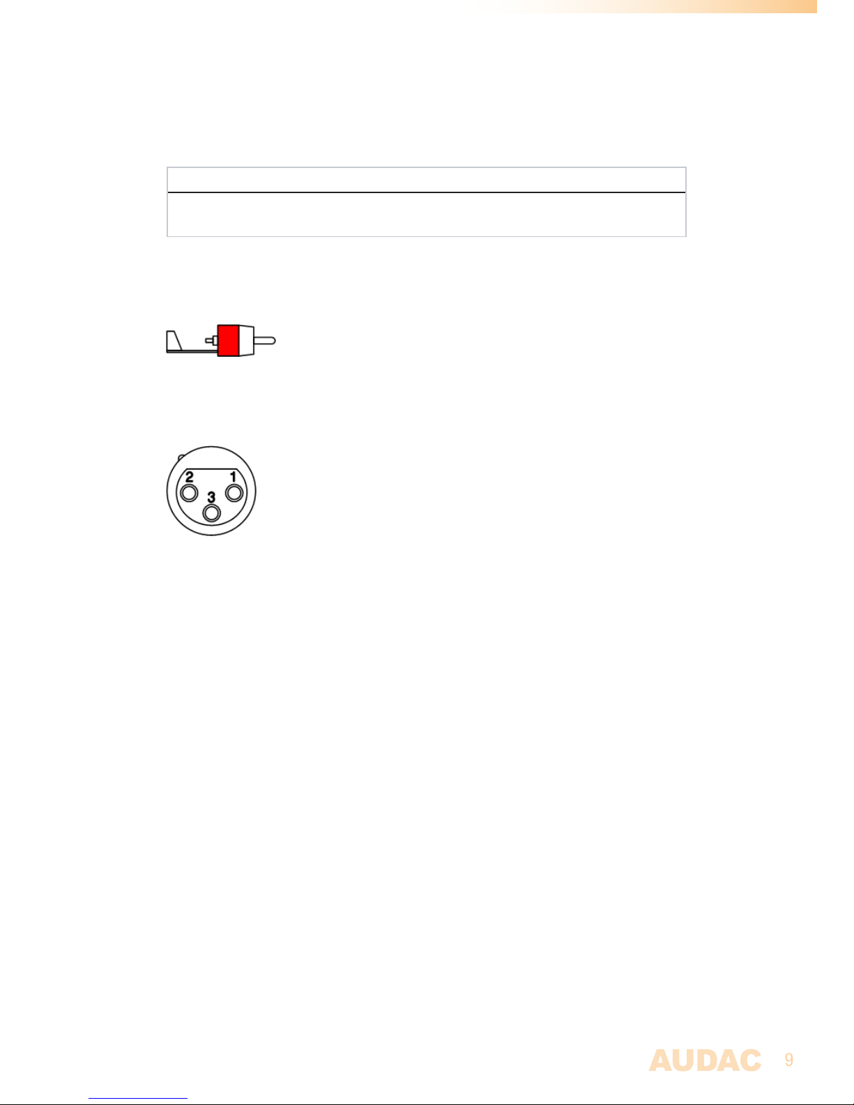
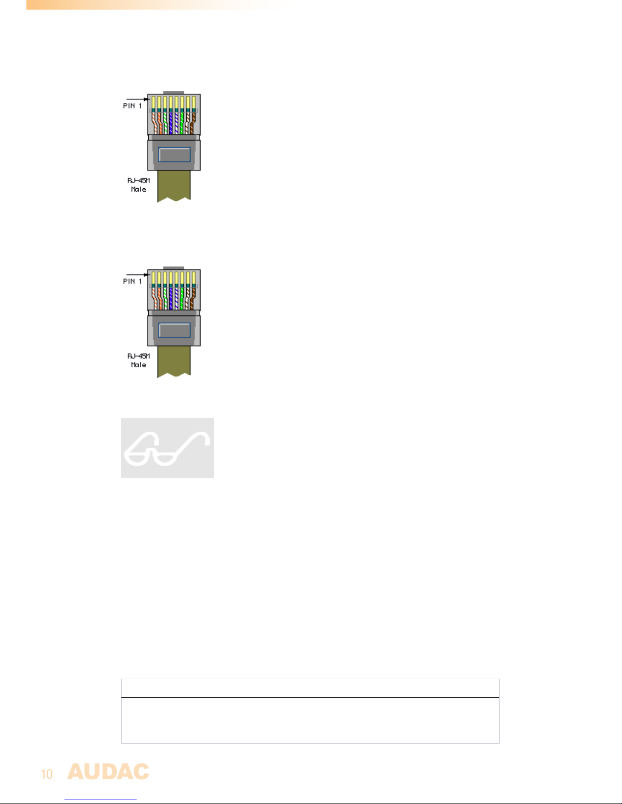
Thebalancedline-levelzoneoutputsareperformedusing3-pinEuro-terminalblock
connectors,eachofthemaccompaniedwithanRJ45connectorforconnectingadditional
wallpanelstothatzone.
A24voltspowerconnectionmakesitpossibletokeeptheMTXrunningonemergencypower,
evenifthemainspowerisshutdown.

6
MTX Block Diagram
BlockdiagramshownforMTX88-8ZoneMatrix

7
Precautions
READ FOLLOWING INSTRUCTIONS FOR YOUR OWN SAFETY
ALWAYSKEEPTHESEINSTRUCTIONS.NEVERTHROWTHEMAWAY
ALWAYSHANDLETHISUNITWITHCARE
HEEDALLWARNINGS
FOLLOWALLINSTRUCTIONS
NEVEREXPOSETHISEQUIPMENTTORAIN,MOISTURE,ANYDRIPPINGORSPLASHING
LIQUID.ANDNEVERPLACEANOBJECTFILLEDWITHLIQUIDONTOPOFTHISDEVICE.
DONOTINSTALLTHISUNITNEARANYHEATSOURCESSUCHASRADIATORSOR
OTHERAPPARATUSTHATPRODUCEHEAT
DONOTPLACETHISUNITINENVIRONMENTSWHICHCONTAINHIGHLEVELSOFDUST,
HEAT,MOISTUREORVIBRATION
THISUNITISDEVELOPEDFORINDOORUSEONLY.DONOTUSEITOUTDOORS
PLACETHEUNITONASTABLEBASEORMOUNTITINASTABLERACK
ONLYUSEATTACHMENTS&ACCESSORIESSPECIFIEDBYTHEMANUFACTURER
UNPLUGTHISAPPARATUSDURINGLIGHTNINGSTORMSORWHENUNUSEDFORLONG
PERIODSOFTIME
ONLYCONNECTTHISUNITTOAMAINSSOCKETOUTLETWITHPROTECTIVE
EARTHINGCONNECTION
EC DECLARATION OF CONFORMITY
Thisproductconformstoalltheessentialrequirementsandfurther
relevantspecificationsdescribedinfollowingdirectives:2004/108/EC
(EMC)and2006/95/EC(LVD)
CAUTION - SERVICING
Thisproductcontainsnouserserviceableparts.Referallservicingto
qualifiedservicepersonnel.Donotperformanyservicing(unlessyou
arequalifiedto)

8
CAUTION
Thesymbolsshownareinternationallyrecognizedsymbolsthatwarnaboutpotentional
hazardsofelectricalproducts.Thelightningflashwitharrowpointinanequilateral
trianglemeansthattheunitcontainsdangerousvoltages.Theexclamationpointin
anequilateraltriangleindicatesthatitisnecessaryfortheusertorefertotheusers
manual.
Thesesymbolswarnthattherearenouserserviceablepartsinsidetheunit.Donot
opentheunit.Donotattempttoservicetheunityourself.Referallservicingtoqualified
personnel.Openingthechassisforanyreasonwillvoidthemanufacturer’swarranty.Do
notgettheunitwet.Ifliquidisspilledontheunit,shutitoffimmediatelyandtakeittoa
dealerforservice.Disconnecttheunitduringstormstopreventdamage.
WASTE ELECTRICAL AND ELECTRONIC EQUIPMENT (WEEE)
TheWEEEmarkingindicatesthatthisproductshouldnotbedisposed
withregularhousholdwasteattheendofitsworkinglife.Thisregulation
iscreatedtopreventanypossibleharmtotheenvironmentorhuman
health.
Thisproductisdevelopedandmanufacturedwithhighqualitymaterials
andcomponentswhichcanberecycledand/orreused.Pleasedispose
thisproducttoyourlocalcollectionpointorrecyclingcentreforelectrical
andelectronicwaste.Thiswillmaketosurethatitwillberecycled
onanenvironmentallyfriendlymanner,andwillhelptoprotectthe
environmentinwhichwealllive.

9
Chapter 1
Pin connections and connectors
CONNECTION STANDARDS
Thein-andoutputconnectionsforAUDACaudioequipmentareperformedcorresponding
tointernationalwiringstandardsforprofessionalaudioequipment.
Cinch (RCA):
Forunbalancedlineinputconnections
Tip: Signal Sleeve: Ground
White: Left Red: Right
XLR:
Forbalancedmicrophoneinputconnections
Pin 1: Ground
Pin 2: Signal+
Pin 3: Signal-
3-Pin Euro-Terminal Block:
Forbalancedlineoutputconnections
Left: Signal- (XLRPin3)
Center:Signal+ (XLRPin2)
Right: Ground (XLRPin1)

10
RJ45 (RS485, Audio, +24V DC):
ForconnectiontoWallPanels
Pin 1 White-Orange AUDIOWLI&MWX65+
Pin 2 Orange AUDIOWLI&MWX65-
Pin 3 White-Green +24VDC
Pin 4 Blue RS485A
Pin 5 White-Blue RS485B
Pin 6 Green GND
Pin 7 White-Brown AUDIOWMI+
Pin 8 Brown AUDIOWMI-
RJ45 (RS485, Audio, +24V DC):
ForconnectiontoPagingconsole
Pin 1 White-Orange Notconnected
Pin 2 Orange Notconnected
Pin 3 White-Green +24VDC
Pin 4 Blue RS485A
Pin 5 White-Blue RS485B
Pin 6 Green GND
Pin 7 White-Brown AUDIOMIC+
Pin 8 Brown AUDIOMIC-
ATTENTION
Thetwistedpaircablingmustalwaysbe‘straight’.Incaseof
self-madecablingitmustbewiredasdescribedabove,toensure
aproperfunctioningofthesystem.
RS232 (serial connection interface):
Forconnectionwithhomeautomationsystems,orotherremotecontrolequipment
Connection StandardRS232
PIN 2 MTXTX
PIN 3 MTXRX
PIN 5 GND
Settings 19200Baud
8Bit
1Stopbit
Noparity
NoHandshaking
RS232 / RS485 / TCP/IP
TheMTXhasRS232,RS485andTCP/IPportswhichallacceptthesamecommands.The
completecommandsettocontroltheMTXisavailableintheMTXcommandsusermanual
whichisfreelydownloadableonwww.audac.eu

11
Wire up the system
Thewiringofthesystemmustbedoneaccordingtothefollowingrules,toguaranteea
properfunctioningofthesysteminallcircumstances.
1. WallMountedInput&Controlunits:
MWX43/45 UTP/FTPCat5ecableorbetter
MWX65 UTP/FTPCat5ecableorbetter
MPX48/88 UTP/FTPCat5ecableorbetter
2. Musicsourcesandzoneoutputs:
Mustbeconnectedwithhigh-qualityaudiocableandhigh-quality
connectors
3. Ethernetconnection:
UTP/FTPCat5ecableorbetter

12
Chapter 2
Front & rear panel
ThefrontpaneloftheMTXenablesyoutofullycontrolandconfigurethesettingsofevery
outputzone.Everyoutputzonecontainsitsownspecificcontrolsection,includingonerotary
functiondial,fourfunctionindicationLED’s,andeightlevel/selectionindicationLED’s.
Abuilt-inpre-listeningloudspeakermakesitpossibletopre-listeneveryoutputchannel
withoutrequiringanadditionalheadphone.Thechannelwhichiscurrentlyplayingthroughthe
built-inpre-listeningloudspeakercanbeselectedbymeansofthePFLselectionswitches
withwhicheachzonecontrolsectionisprovided.ThelevelofthePFLloudspeakercanbe
controlledbyusingthePFLpotentiometer.
Ontherightsidethereisapowerbuttonprovided.Simplypushthisbuttontopower-up
thesystem.
Front Panel overview
MTX48
POWER
Zone 2
LEVEL
MTX48
ON
VOLUME
INPUT
BASS
TREBLE
8
7
6
5
4
3
2
1
PFL
Zone 3 Zone 4 PFL
Zone 1
VOLUME
INPUT
BASS
TREBLE
8
7
6
5
4
3
2
1
PFL
VOLUME
INPUT
BASS
TREBLE
8
7
6
5
4
3
2
1
PFL
VOLUME
INPUT
BASS
TREBLE
8
7
6
5
4
3
2
1
PFL
MTX88
POWER
Zone 2
LEVEL
MTX88
ON
VOLUME
INPUT
BASS
TREBLE
8
7
6
5
4
3
2
1
PFL
Zone 3 Zone 4 Zone 5 Zone 6 Zone 7 Zone 8 PFL
Zone 1
VOLUME
INPUT
BASS
TREBLE
8
7
6
5
4
3
2
1
PFL
VOLUME
INPUT
BASS
TREBLE
8
7
6
5
4
3
2
1
PFL
VOLUME
INPUT
BASS
TREBLE
8
7
6
5
4
3
2
1
PFL
VOLUME
INPUT
BASS
TREBLE
8
7
6
5
4
3
2
1
PFL
VOLUME
INPUT
BASS
TREBLE
8
7
6
5
4
3
2
1
PFL
VOLUME
INPUT
BASS
TREBLE
8
7
6
5
4
3
2
1
PFL
VOLUME
INPUT
BASS
TREBLE
8
7
6
5
4
3
2
1
PFL

13
Front Panel functions
Thecontrolsectionforeveryzonecontainsonerotaryfunctiondial,fourfunctionindica-
tionLED’sandeightlevel/selectionindicationLED’s.
Zone 1
VOLUME
INPUT
BASS
TREBLE
8
7
6
5
4
3
2
1
PFL
BymeansofthefunctionindicationLED’s,thecurrentoperatingfunctionwillbeindicated.
TheupperLEDstandsforvolumeadjustment,thesecondLEDstandsforinputchannel
selection,thethirdLEDwillblinkwhenBasstoneadjustmentisenabled,andthefourth
LEDwillblinkwhenTrebletoneadjustmentisenabled.
Theselectionofwhichfunctionhastobecontrolledcanbedonebypressingtherotary
functiondial.Whenpressingtherotaryfunctiondial,the‘Volume’LEDwillilluminate.
Changingtothedesiredfunctioncanbedonebyrotatingthefunctiondial.Thecurrently
setlevel/selectionwillappearwhenthefunctionisselected.Whenanychangeneedsto
bemadetothelevel/selection,therotarybuttonshouldbepressedasecondtime.The
LEDoftheselectedfunctionwillstartblinkingnow,andanyrotationtothefunctiondial
willaffectthesetlevel/selection.
Whenthelevel/selectionischangedtothedesiredlevelandanyotherchangeneedsto
bemade,youcanreturntofunctionselectionbypressingtherotarybuttonagain.The
settingsmenuwillbequitautomaticallywhentherotarydialisnotoperatedforabout6
seconds.
Volume adjustment:
Whennofunctionisselected(MTXinidlestatus)andthefunctiondialisrotated,the
volumeadjustmentfunctionwillbeautomaticallyactivated.ThevolumeLEDwillstart
blinkingandthecurrentvolumelevelwillilluminateonthelevel/selectionLED’s.Manual
switchingtovolumemodecanalsobedone,bytheprocedureasdescribedabove.The
level/selectionLED’swillindicatethecurrentlysetvolumelevel.Onlyafewilluminated
LED’scorrespondwithalowvolumelevel,andmanyilluminatedLED’scorrespond
withahighvolumelevel.Rotatingtherotaryfunctiondialinclockwisedirectionresults
inanincreasingvolumelevelandrotatingincounter-clockwisedirectionresultsina
decreasingvolumelevel.
Input selection:
Thedesiredinputchannelforeveryzonecanbeselected.EveryLEDcorrespondswith
aninputchannel,andthecorrespondingLEDfortheselectedinputchannelwillilluminate
whenselected.Switchingbetweenthedifferentinputchannelscanbedonebyrotating
thefunctiondial.Thetabelshownbelowgivesanoverviewofwhichnumbercorresponds
withwhichinputchannel.
Rotary
Functiondial
Level/Selection
indicationLED’s
Function
indicationLED’s
PFLSwitch

14
Input number Corresponding channel
1
2
3
4
5
6
7
8
MicrophoneInput1
MicrophoneInput2
Lineinput3
Lineinput4
Lineinput5
Lineinput6
Line(WLI)+MWX65WallPanelInput
Microphone(WMI)WallPanelInput
Bass and Treble adjustment:
TheBassandTrebleadjustmentcanbedoneonasimilarway.Whenthedesiredfunctionis
selected,thecorrespondingfunctionLEDwillstartblinking.Theadjustmentcanbedonebyrotating
thefunctiondial.Similartothevolumeadjustment,clockwiserotationresultsinalevelincrease
whilecounter-clockwiserotationresultsinaleveldecrease.Whenthelevelissetinneutral
position(0dB),noLED’softhelevel/selectionLED’swillilluminate.Whenanamplification(dB+)
isselected,theupperfourLED’swillilluminatefromoutthecentre,dependingontheselectedlevel.
Whenanattenuationisselected(dB-),thelowerfourLED’swillilluminatefromoutthecentre,
dependingoftheselectedlevel.
POWER
LEVEL
MTX88
ON
PFL
Built-in PFL Loudspeaker and potentiometer:
Thebuilt-inpre-listeningloudspeakermakesitpossibletopre-listeneveryoutputchannelwithout
theneedforanadditionalheadphone.Thechannelwhichiscurrentlyplayingthroughthebuilt-in
pre-listeningloudspeakercanbeselectedbymeansofthePFLselectionswitcheswhicharepro-
videdwitheachzonecontrolsection.ThelevelofthePFLloudspeakercanbecontrolledbyusing
thePFLpotentiometer.
Power switch:
Bymeansofthepowerswitch,thedevicecanbeturnedONandOFF.Whenthedeviceisswitched
on,theblueLEDabovethepowerbuttonwillilluminate.
Powerswitch
Built-inPFL
Loudspeaker
PFLLevel
Potentiometer

15
Functions overview
Operation functions
Change
Volume
-SetfunctionLEDto‘Volume’
-Pushrotarydialonce
-Rotatefunctiondialtodesiredvolumelevel
->TheindicationLED’sshowtheselectedvolumelevel
-Pushrotarydialoncetoreturnbacktomainmenu
Change
Routing
-SetfunctionLEDto‘Routing’
-Pushrotarydialonce
-Rotatefunctiondialtodesiredinputchannel
->TheindicationLED’sshowtheselectedinputchannel(1-8)
-Pushrotarydialoncetoreturnbacktomainmenu
Change Bass -SetfunctionLEDto‘Bass’
-Pushrotarydialonce
-Rotatefunctiondialtodesiredbasslevel
->TheindicationLED’sshowtheselectedlevel
-Inneutalposition,allLED’sareoff
-IncreasedlevelcausesupperLED’stoilluminate
-DecreasedlevelcauseslowerLED’stoilluminate
-Pushrotarydialoncetoreturnbacktomainmenu
Change Treble -SetfunctionLEDto‘Treble’
-Pushrotarydialonce
-Rotatefunctiondialtodesiredtreblelevel
->TheindicationLED’sshowtheselectedlevel
-Inneutalposition,allLED’sareoff
-IncreasedlevelcausesupperLED’stoilluminate
-DecreasedlevelcauseslowerLED’stoilluminate
-Pushrotarydialoncetoreturnbacktomainmenu
Pre-Fade
Listen
-PressPFLbutton
->Selectedchannelnowplaysthroughthebuilt-inloudspeaker
Save Settings -HoldrotarybuttonforZone1andZone2for3seconds
->SavedsettingswillberecalledafterMTXrestart

16
Configuration functions
Priority 1
Enable /
Volume
(per zone)
PrioritymessagefromMicrophoneInput1willbeannouncedto
priorityenabledzones.
-SetLEDforcorrespondingzoneto‘Volume’
-Holdrotarybuttonforcorrespondingchanneldownfor3seconds
(VolumeLEDstartsblinkingrapidly)
-Prioritycanbeenabledandvolumecanbesetbyrotatingthe
button(Priorityisdisabledwhenvolumeissettozero)
-Pressrotarybuttononceagaintoreturnbacktomainmenu
Priority 2
Enable /
Volume
(per zone)
PrioritymessagefromMicrophoneInput2willbeannouncedto
priorityenabledzones.
-SetLEDforcorrespondingzoneto‘Routing’
-Holdrotarybuttonforcorrespondingchanneldownfor3seconds
(RoutingLEDstartsblinkingrapidly)
-Prioritycanbeenabledandvolumecanbesetbyrotatingthe
button(Priorityisdisabledwhenvolumeissettozero)
-Pressrotarybuttononceagaintoreturnbacktomainmenu
Paging Volume
(per zone)
PagingvolumeformessagefromExternalPagingConsolecanbeset.
-SetLEDforcorrespondingzoneto‘Bass’
-Holdrotarybuttonforcorrespondingchanneldownfor3seconds
(BassLEDstartsblinking)
-Pagingvolumecanbesetbyrotatingthebutton
(Pagingisdisabledwhenvolumeissettozero)
-Pressrotarybuttononceagaintoreturnbacktomainmenu
Mono / Stereo
output
(per zone)
OutputsignalforeachzonecanbeswitchedbetweenMonoand
Stereo
-Whilepowering-upthedevice,holdtherotarybuttonrforZone1.
TheMono/Stereosettingsmenuwillbedisplayed
-TogglingbetweenStereoorMonomodecanbedonebyusingeach
zones’rotarybutton
-LED1:ZonesettoMono
-LED2:ZonesettoStereo
-PoweroffandPoweronthedeviceagaintogobacktonormal
operationmode.
Set Wall Panel
Address
Connectedwallpanelscanbeassignedtoonezone.
-SetLEDforcorrespondingzoneto‘Treble’
-Holdrotarybuttonforcorrespondingchanneldownfor3seconds
(Allconnectedwallpanelswillstartblinking)
-Pressupperbuttonfromthewallpaneltoassignthiswallpanelto
thecorrespondingzone
-Repeatthisactiontoassignmultiplewallpanelstothiszone

17
TherearsideoftheMTXcontainsalldifferentkindsconnectorswhicharenecessaryto
connectthedevice.
Power, RS232, Ethernet & Paging connectors:
CLIP
PAGING
Zone 8
Line 5 Line 4 Line 3Line 6
Mic 1Mic 2
-14 +9
PHANTOM
GAIN
-50 0
MTX88
AUDAC
Caution: Only use
fuses of the same type
Warning: Do not
expose this equipment
to rain or moisture
GAIN
MID
-15 +15
HIGH
-15 +15
LOW
-15 +15
MID
-15 +15
HIGH
-15 +15
LOW
-15 +15
PHANTOM
GAIN
-50 0
AC Input
100-240V 50/60Hz
Fuse: T1AL/250V
ETHERNET
RS-232
WP
GND
R+
R-
GND
L+
L-
Zone 7
WP
GND
R+
R-
GND
L+
L-
Zone 6
WP
GND
R+
R-
GND
L+
L-
Zone 5
WP
GND
R+
R-
GND
L+
L-
Zone 4
WP
GND
R+
R-
GND
L+
L-
Zone 3
WP
GND
R+
R-
GND
L+
L-
Zone 2
WP
GND
R+
R-
GND
L+
L-
Zone 1
WP
GND
R+
R-
GND
L+
L-
CLIP CLIP CLIP
CLIP CLIP
GND
+24 V
-14 +9
GAIN
-14 +9
GAIN
-14 +9
GAIN
WP
Power inlet:
Themainspowersupply(110~240VAC/50~60Hz)hastobeappliedtothisACpower
inlet.TheconnectionismadebyanIECpowerconnectorandisfittedwithafuse.When
replacingthefuse,makesurethatthevalueofthereplacementfusematchesthevalueof
theoriginalfuse.(T1AL/250V)
Emergency power inlet (24 Volt):
A24Voltsemergencypowersupplycanbeconnectedtothis2-pinTerminalblock
connectorforkeepingtheMTXrunningonemergencypowerwhenthemainspoweris
shutdown.WhentheMTXisrunningon24Voltemergencypower,thefunctionofthe
powerswitchonthefrontpanelisbypassedandcan’tswitchtheMTXoff.
Rear Panel overview
MTX48
MTX88
CLIP
PAGING
Line 5 Line 4 Line 3Line 6
Mic 1Mic 2
-14 +9
PHANTOM
GAIN
-50 0
MTX48
AUDAC
Caution: Only use
fuses of the same type
Warning: Do not
expose this equipment
to rain or moisture
GAIN
MID
-15 +15
HIGH
-15 +15
LOW
-15 +15
MID
-15 +15
HIGH
-15 +15
LOW
-15 +15
PHANTOM
GAIN
-50 0
AC Input
100-240V 50/60Hz
Fuse: T1AL/250V
ETHERNET
RS-232 Zone 4
WP
GND
R+
R-
GND
L+
L-
Zone 3
WP
GND
R+
R-
GND
L+
L-
Zone 2
WP
GND
R+
R-
GND
L+
L-
Zone 1
WP
GND
R+
R-
GND
L+
L-
CLIP CLIP CLIP
CLIP CLIP
GND
+24 V
-14 +9
GAIN
-14 +9
GAIN
-14 +9
GAIN
WP
CLIP
PAGING
Zone 8
Line 5 Line 4 Line 3Line 6
Mic 1Mic 2
-14 +9
PHANTOM
GAIN
-50 0
MTX88
AUDAC
Caution: Only use
fuses of the same type
Warning: Do not
expose this equipment
to rain or moisture
GAIN
MID
-15 +15
HIGH
-15 +15
LOW
-15 +15
MID
-15 +15
HIGH
-15 +15
LOW
-15 +15
PHANTOM
GAIN
-50 0
AC Input
100-240V 50/60Hz
Fuse: T1AL/250V
ETHERNET
RS-232
WP
GND
R+
R-
GND
L+
L-
Zone 7
WP
GND
R+
R-
GND
L+
L-
Zone 6
WP
GND
R+
R-
GND
L+
L-
Zone 5
WP
GND
R+
R-
GND
L+
L-
Zone 4
WP
GND
R+
R-
GND
L+
L-
Zone 3
WP
GND
R+
R-
GND
L+
L-
Zone 2
WP
GND
R+
R-
GND
L+
L-
Zone 1
WP
GND
R+
R-
GND
L+
L-
CLIP CLIP CLIP
CLIP CLIP
GND
+24 V
-14 +9
GAIN
-14 +9
GAIN
-14 +9
GAIN
WP

18
RS232 Connection:
TheRS232connectioncanbeusedtocontroltheMTXthroughexternalhardwaresuchas
anhomeautomationsystemorcomputer.Connectyourexternalcontrolhardwaretothis
port.Thepinoutandcommunicationsettingsaredescribedinanearlierchapterofthis
usermanual.ThecompleteRS232commandinstructionsetandconfigurationinformation
canbedownloadedfromtheAUDACwebsite.
Ethernet RJ45 Connector:
ThisconnectorshouldbeconnectedtoaLANNetwork.Thismakesitpossibletocontrol
theMTXoverEthernet.ThecontrolcanbedonebysendingcommandsoverTCP/IP,bya
devicewithastandardwebbrowsersupportingflashorbyusingspecialappswhichare
designedtobeusedincombinationwithmobileapplications.(Smartphones&Tablets)For
moreinformationabouttheEthernetconfigurationofthisdevice,check‘Chapter4:User
interface&Configuration’and‘Chapter6:IPBasics’ofthisusermanual.
Paging RJ45 Connector:
The(optional)MPXpagingconsolesmustbeconnectedtothe‘PAGING’RJ45connector.
Thisallowstoannouncemessagesthroughthemicrophoneofthepagingconsoletoall
thezonesoftheMTX.Theselectionofwhichannouncementsshouldbemadeinwhich
zonecanbedoneonthecontrolpaneloftheMPXpagingconsoles.(MPX48-4zonefor
MTX48andMPX88-8zoneforMTX88)
Wall Panel & Zone output connectors:
CLIP
PAGING
Zone 8
Line 5 Line 4 Line 3Line 6
Mic 1Mic 2
-14 +9
PHANTOM
GAIN
-50 0
MTX88
AUDAC
Caution: Only use
fuses of the same type
Warning: Do not
expose this equipment
to rain or moisture
GAIN
MID
-15 +15
HIGH
-15 +15
LOW
-15 +15
MID
-15 +15
HIGH
-15 +15
LOW
-15 +15
PHANTOM
GAIN
-50 0
AC Input
100-240V 50/60Hz
Fuse: T1AL/250V
ETHERNET
RS-232
WP
GND
R+
R-
GND
L+
L-
Zone 7
WP
GND
R+
R-
GND
L+
L-
Zone 6
WP
GND
R+
R-
GND
L+
L-
Zone 5
WP
GND
R+
R-
GND
L+
L-
Zone 4
WP
GND
R+
R-
GND
L+
L-
Zone 3
WP
GND
R+
R-
GND
L+
L-
Zone 2
WP
GND
R+
R-
GND
L+
L-
Zone 1
WP
GND
R+
R-
GND
L+
L-
CLIP CLIP CLIP
CLIP CLIP
GND
+24 V
-14 +9
GAIN
-14 +9
GAIN
-14 +9
GAIN
WP
Wall Panel RJ45 Connectors:
EveryzonehasitsspecificWallPanel(WP)RJ45connectorwheretoadditionalwall
panelscanbeconnected.EveryzonehasthepossibilitytoconnectanadditionalLineand
Microphoneinputunitandmultiplewallpanelcontrollers.Ontheseportsarebothdigital
RS485controlsignalsaswellasdifferentialaudiosignalstransmitted.
Zone outputs (Terminal Block):
ThezoneoutputsoftheMTXarestereo(switcheabletomono)balancedline-level
outputs.Dependingontherequirementsforeachspecificapplication,thesuitable
amplifiersshouldbeconnectedtotheseoutputconnectors.Theusedconnectorsare
3-pinTerminal-Blockconnectors.

19
Input connectors:
CLIP
PAGING
Zone 8
Line 5 Line 4
Line 3
Line 6
Mic 1
Mic 2
-14 +9
PHANTOM
GAIN
-50 0
MTX88
AUDAC
Caution: Only use
fuses of the same type
Warning: Do not
expose this equipment
to rain or moisture
GAIN
MID
-15 +15
HIGH
-15 +15
LOW
-15 +15
MID
-15 +15
HIGH
-15 +15
LOW
-15 +15
PHANTOM
GAIN
-50 0
AC Input
100-240V 50/60Hz
Fuse: T1AL/250V
ETHERNET
RS-232
WP
GND
R+
R-
GND
L+
L-
Zone 7
WP
GND
R+
R-
GND
L+
L-
Zone 6
WP
GND
R+
R-
GND
L+
L-
Zone 5
WP
GND
R+
R-
GND
L+
L-
Zone 4
WP
GND
R+
R-
GND
L+
L-
Zone 3
WP
GND
R+
R-
GND
L+
L-
Zone 2
WP
GND
R+
R-
GND
L+
L-
Zone 1
WP
GND
R+
R-
GND
L+
L-
CLIP CLIP
CLIP
CLIP
CLIP
GND
+24 V
-14 +9
GAIN
-14 +9
GAIN
-1
4 +9
GAIN
WP
RCA / Cinch Line inputs:
UnbalancedLine-Levelinputsources(E.g.CD-Players,Tuners,MP3Players,...)
shouldbeconnectedtotheLinelevelinputsLine3toLine6.Thesearestandardline-
levelstereoinputsperformedwithRCAconnectors.Allofthemhaveagaincontrol
potentiometerwherebytheleveloftheinputsignalcanbecontrolledwithinarangeof
-14dB~+9dB.
TheclippingLEDilluminateswhenthesignalreachestheclippinglevel.
Balanced microphone inputs:
Balancedmonosources(E.g.Microphones)shouldbeconnectedtoinputsMic1andMic
2.BothchannelsareperformedwithFemaleXLRconnectorprovidedwithgaincontrol
potentiometerwherebytheleveloftheinputsignalcanbecontrolledwithinarangeof
-50dB~0dB.ThismakesitpossibletoconnectbothLinelevelinputsourcesaswellas
Microphonelevelinputsources.TheclippingLEDilluminateswhenthesignalreachesthe
clippinglevel.
Inaddition,bothchannelshaveathree-bandtonecontrolwherebyspecificfrequency
rangescanbeadjustedwithinarangeof±15dBandaphantompowerswitch,whereby
the15Voltsphantompowercanbeenabledforpoweringcondensermicrophones.

20
Chapter 3
MTX Quick start guide
This chapter guides you through the setup process of a basic project with one MTX audio
matrix and 8 standard MWX43/45 wall panels, two All-In-One MWX65 wall panels and some
regular Line & Microphone input sources.
Overview of the MTX setup
Connecting the MTX
ATTENTION
MakesurethepowerofthedeviceisturnedOFFbeforeanyconnectionsorwiring
adjustmentsaremade.Whendisregardingthisrule,itcanleadtopermanentdamageof
theequipment
1) Connecting audio sources
ConnectalltheMicrophonestotheXLRconnectorsontherearsideoftheMTX.When
usingcondensermicrophones,makesurethephantompowerswitchisturnedON.
ConnectalltheLine-Levelaudiosources(CD-Players,MP3Players,Tuners,...)tothe
RCAconnectorsontherearsideoftheMTX.Adjustallinputgainstotheappropriatelevel
sonoinputclippingoccurs.
2) Connecting amplifiers and/or speakers
Connectamplifiers(100VorLowimpedance)tothebalancedoutputsoftheMTX(Three-
pinEuro-TerminalBlock).Theamplifierconfiguration(100VorLowimpedance)andpower
needstobechosenaccordingtotherequirementsforeachspecificapplication.Inits
standardconfiguration,theMTXhasBalancedStereooutputs,whichcanbeswitchedto
BalancedMonooutputs.(Seeconfigurationfunctions)
Amplifiers
Audiosources
Wallpanels
Prog.
Vol
+
-
+
-
Prog.
Vol
+
-
+
-
Prog.
Vol
+
-
+
-
Prog.
Vol
+
-
+
-
Prog.
Vol
+
-
+
-
CLIP
PAGING
Zone 8
Line 5 Line 4 Line 3Line 6
Mic 1Mic 2
-14 +9
PHANTOM
GAIN
-50 0
MTX88
AUDAC
Caution: Only use
fuses of the same type
Warning: Do not
expose this equipment
to rain or moisture
GAIN
MID
-15 +15
HIGH
-15 +15
LOW
-15 +15
MID
-15 +15
HIGH
-15 +15
LOW
-15 +15
PHANTOM
GAIN
-50 0
AC Input
100-240V 50/60Hz
Fuse: T1AL/250V
ETHERNET
RS-232
WP
GND
R+
R-
GND
L+
L-
Zone 7
WP
GND
R+
R-
GND
L+
L-
Zone 6
WP
GND
R+
R-
GND
L+
L-
Zone 5
WP
GND
R+
R-
GND
L+
L-
Zone 4
WP
GND
R+
R-
GND
L+
L-
Zone 3
WP
GND
R+
R-
GND
L+
L-
Zone 2
WP
GND
R+
R-
GND
L+
L-
Zone 1
WP
GND
R+
R-
GND
L+
L-
CLIP CLIP CLIP
CLIP CLIP
GND
+24 V
-14 +9
GAIN
-14 +9
GAIN
-14 +9
GAIN
WP
Prog.
Vol
+
-
+
-
Prog.
Vol
+
-
+
-
AUDAC
LINE IN
MIC IN
Prog.
Vol
+
-
+
-
AUDAC
LINE IN
MIC IN
Other manuals for MTX48
1
This manual suits for next models
1
Table of contents
Other AUDAC Recording Equipment manuals