AUDAC XMP44 User manual

XMP44
User Manual
www.audac.eu

2

3
Index
Introduction 5
Precautions 5
Safety requirements 6
Caution servicing 6
EC Declaration of Conformity 6
Waste of Electrical and Electronic Equipment (WEEE) 7
Caution 7
Chapter 1: Pin connections and connectors 8
Connection standards 8
Chapter 2: Front & rear panel 10
Front panel overview 10
Front panel description 10
Rear panel overview 11
Rear panel description 11
Chapter 3: User interface & control 12
Front panel control 12
Main 13
Module 13
Module settings 14
General settings 15
Network settings 16
Web-control interface 17
Login 17
Main 17
Module 19
Settings 19
Chapter 4: Installing the modules 21
Chapter 5: Additional information 23
IP Basics 23
Technical specifications 24
Notes 25

4

5
Introduction
SourceCon™ Professional modular audio system
The XMP44 is a professional modular audio system with 4 SourceCon™ interface card
slots whereto a wide variation of optional modules can be installed. The variety of available
modules ranges from FM tuners to DAB&DAB+ tuners, internet radio tuners, voice file
interfaces and many more.
The flexible architecture allows any project combination up to four sources, resulting in a
truly versatile solution that will live up the needs for any user taking high regard of crystal
clear audio reproduction. Simultaneous operation for all four modules makes it a compact
multi-source system which is the perfect expansion for any multi-zone audio system.
The front panel of the system accommodates a 2.8” TFT display in combination with a
push rotary function dial and 4 tactile pushbuttons. The controls and indicators on the front
panel of the unit are guaranteeing an intuitive and user friendly operation, allowing hassle
free operation and configuration to even unexperienced users. Four USB interfaces (one for
each module) are enabling playback or storage of media and voice file, while pre-listening
for each output is possible through a built-in PFL speaker with individual volume control.
Both RS-232 and TCP/IP communication ports are implemented, allowing system integration
with any home or industrial automation system. Using the freely available Audac Touch™
application for smart devices guarantees total system control and configuration from any
device on any location and at any time.

6
Precautions
READ FOLLOWING INSTRUCTIONS FOR YOUR OWN SAFETY
ALWAYS KEEP THESE INSTRUCTIONS. NEVER THROW THEM AWAY
ALWAYS HANDLE THIS UNIT WITH CARE
HEED ALL WARNINGS
FOLLOW ALL INSTRUCTIONS
NEVER EXPOSE THIS EQUIPMENT TO RAIN, MOISTURE, ANY DRIPPING OR SPLASHING
LIQUID. AND NEVER PLACE AN OBJECT FILLED WITH LIQUID ON TOP OF THIS DEVICE.
DO NOT PLACE THIS UNIT IN AN ENCLOSED ENVIRONMENT SUCH AS A BOOKSHELF
OR CLOSET. ENSURE THERE IS ADEQUATE VENTILATION TO COOL THE UNIT. DO NOT
BLOCK THE VENTILATION OPENINGS.
DO NOT STICK ANY OBJECTS THROUGH THE VENTILATION OPENINGS.
DO NOT INSTALL THIS UNIT NEAR ANY HEAT SOURCES SUCH AS RADIATORS OR
OTHER APPARATUS THAT PRODUCE HEAT
DO NOT PLACE THIS UNIT IN ENVIRONMENTS WHICH CONTAIN HIGH LEVELS OF DUST,
HEAT, MOISTURE OR VIBRATION
THIS UNIT IS DEVELOPED FOR INDOOR USE ONLY. DO NOT USE IT OUTDOORS
PLACE THE UNIT ON A STABLE BASE OR MOUNT IT IN A STABLE RACK
ONLY USE ATTACHMENTS & ACCESSORIES SPECIFIED BY THE MANUFACTURER
UNPLUG THIS APPARATUS DURING LIGHTNING STORMS OR WHEN UNUSED FOR LONG
PERIODS OF TIME
ONLY CONNECT THIS UNIT TO A MAINS SOCKET OUTLET WITH PROTECTIVE
EARTHING CONNECTION
EC DECLARATION OF CONFORMITY
This product conforms to all the essential requirements and further
relevant specifications described in following directives: 2004/108/EC
(EMC) and 2006/95/EC (LVD)
CAUTION - SERVICING
This product contains no user serviceable parts. Refer all servicing to
qualified service personnel. Do not perform any servicing (unless you
are qualified to)

7
CAUTION
The symbols shown are internationally recognized symbols that warn about potentional
hazards of electrical products. The lightning flash with arrowpoint in an equilateral
triangle means that the unit contains dangerous voltages. The exclamation point in
an equilateral triangle indicates that it is necessary for the user to refer to the users
manual.
These symbols warn that there are no user serviceable parts inside the unit. Do not
open the unit. Do not attempt to service the unit yourself. Refer all servicing to qualified
personnel. Opening the chassis for any reason will void the manufacturer’s warranty. Do
not get the unit wet. If liquid is spilled on the unit, shut it off immediately and take it to a
dealer for service. Disconnect the unit during storms to prevent damage.
WASTE ELECTRICAL AND ELECTRONIC EQUIPMENT (WEEE)
The WEEE marking indicates that this product should not be disposed
with regular houshold waste at the end of its life cycle. This regulation
is created to prevent any possible harm to the environment or human
health.
This product is developed and manufactured with high quality materials
and components which can be recycled and/or reused. Please
dispose this product at your local collection point or recycling centre
for electrical and electronic waste. This will make sure that it will be
recycled on an environmentally friendly manner, and will help to protect
the environment in which we all live.
ADDITIONAL INFORMATION
This manual is put togheter with much care, and is as complete as could be on the
publication date. However, updates on the specifications, functionality or software may
have occurred since publication. To obtain the latest version of both manual and software,
please visit the Audac website @ www.audac.eu.

8
Chapter 1
Pin connections and connectors
CONNECTION STANDARDS
The in- and output connections for AUDAC audio equipment are performed corresponding
to international wiring standards for professional audio equipment.
3-Pin Terminal Block:
For balanced signal input & link output connections.
Left: Signal - (XLR Pin 3)
Center: Signal + (XLR Pin 2)
Right: Ground (XLR Pin 1)
For balanced line input connections:
For balanced line output connections:
For unbalanced line in & output connections:

9
RS232 (serial connection interface):
For connection with home automation systems, or other remote control equipment
Connection Standard RS232
PIN 2 XMP44 TX
PIN 3 XMP44 RX
PIN 5 GND
Settings 19200 Baud
8 Bit
1 Stop bit
No parity
No Handshaking
RS232
The XMP44 has an RS232 and TCP/IP ports accepting the same commands. The complete
command set to control the XMP44 is available in the XMP44 commands user manual
which is freely downloadable on www.audac.eu

10
Chapter 2
Front & rear panel
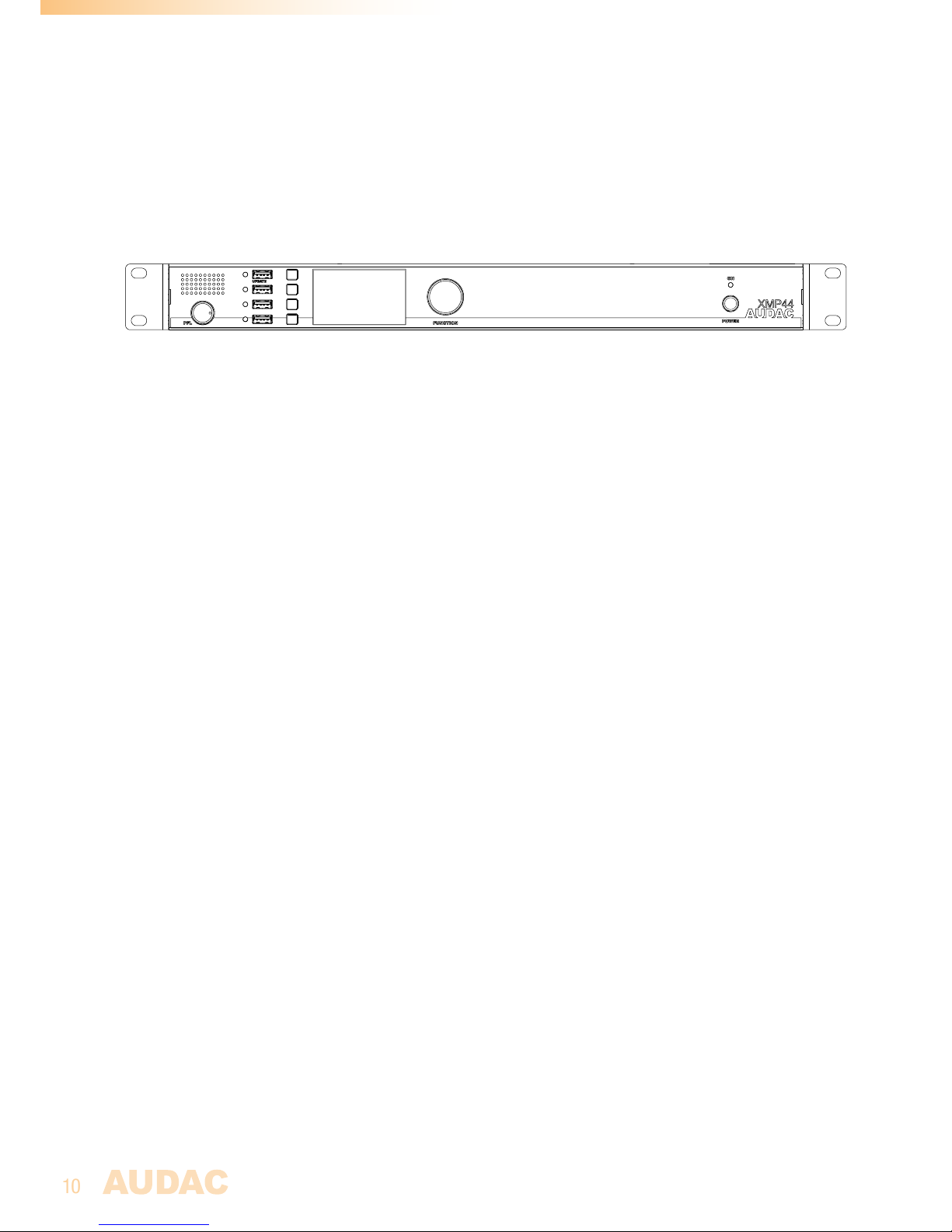
Front Panel overview
Front panel description
PFL Loudspeaker with volume dial:
The built-in PFL loudspeaker allows pre-listening of the outputs of the installed audio
modules without requiring headphones or other tools. The currently enabled audio module
(displayed on the graphical display) will be heard through the PFL speaker. The level of the
PFL loudspeaker can be controlled using the potentiometer located below.
USB Ports (4x):
A USB port for each module slot (4x) is located on the left side of the front panel. Each USB
port is internally connected with the corresponding module slot and can be used (when USB
functions are supported) for data storage, media playback or any other supported function.
The upper USB port (indicated with ‘Update’) supports some extended functionality. Each
USB port is accompanied with a green LED, which indicates whether USB functionality is
supported for the installed module.
Graphical LCD display with tactile push buttons and rotary selection dial:
A clear system overview and intuitive user experience is offered using the 2.8” graphical LCD
display accompanied with four tactile selection buttons (left side) and a rotary selection dial
(right side). The true colour display offers a clear overview of the systems current operation
mode with intuitive and user friendly browsing through the menu structure.
The functionality of the four push buttons depends on the current operation mode and position
in the menu structure. In the main menu, four buttons will be linked with four different module
slots allowing to enter their specific menu and offering access to its further functions. In
other menu’s, corresponding icons are shown on the left side of the display.
Parameter adjustment and browsing is made easy using the rotary function dial. This
multifunctional dial allows easy one-hand operation throughout the entire menu structure.
Browsing through the menu is done by rotating it while actions are made by pressing it.
Power switch:
Allows to power the system ON and OFF. The blue indicator LED illuminates when switched on.

11
Rear Panel overview
Rear panel description
AC Power inlet with fuse:
The mains power supply (100~240 V AC / 50~60 Hz) has to be applied to this AC power
inlet. The connection is made by an IEC C14 power connector and is fitted with a fuse. When
replacing the fuse, make sure that the value of the replacement fuse matches the value of
the original fuse. (T1AL/250V)
RS232 Connection:
The RS232 connection can be used to control the system and its installed modules through
any external hardware such as home and industrial automation systems. The pinout and
communication settings are described in an earlier chapter of this user manual. The complete
RS232 command instruction set and configuration information can be downloaded from the
AUDAC website.
Ethernet RJ45 Connector:
The connection to any LAN network is possible using the RJ45 ethernet connection. This
allows control of the system and its installed modules from any ethernet supported device.
Various possibilities of ethernet control are available, including sending commands over TCP/
IP, controlling the system through the integrated web-interface, or full system control using
the Audac Touch™ application.
For more information about the Ethernet configuration of this device, check ‘Chapter 4: User
interface & Configuration’ and ‘Chapter 6: IP Basics’ of this user manual.
SourceCon™ interface card slots:
Four modular slots are available on the rear panel of the unit, allowing installation for a wide
variation of optional SourceCon™ modules depending of the required system functionality.
The module slots are fitted with a guiding system and connections are made by board-
edge connectors allowing fast and simple installation. Once installed, functionalities are
automatically discovered at startup and made operational by the device software.

12
Chapter 3
User interface & configuration
The XMP44 contains a variation of control and configuration possibilities. The front panel of
the unit is fitted with a 2.8” graphical display unit, allowing instant control and configuration
possibilities through an intuitive and user friendly user interface.
Besides, its functions can be remotely controlled through the embedded web-control
interface. This fully adaptive interface based on HTML5 technology can be accessed from
any websocket supporting device, offering cross-platform compatibility with Windows, Mac
OS, Linux, Android and iOS without requiring any installed applications or web plugins. The
fully adaptive structure guarantees a clear viewing on all different kinds of screen sizes.
When application specific or total system control is required, the XMP44 can be controlled
using the Audac Touch™ application. This application allows to custom configure your control
panel (Dashboard) accordig to project or user specific requirements.
For using the remote web-control or Audac-Touch interface, the XMP44 shall be connected
to an ethernet LAN network and accessed by its IP address. The standard (factory default)
IP address of the XMP44 is 192.168.0.196, make sure this address is within the IP range of
the connected ethernet LAN network (subnetmask 255.255.255.0). If the default network
address is not within range of your LAN network, it can be changed in the settings menu,
using the front panel interface.
Front panel control
The front panel controllable functions are strongly depending of the installed module and
its functionalities. Therefore, it is not possible to describe the menu structure possibilities
for each individual module in detail. An overview of how the entire menu is constructed and
how to navigate through it is given here.
The front panel of the device includes a 2.8” graphical LCD display, which is accompanied with
four tactile push buttons (left side) and a rotary selection dial (right side). This combination
allows you to navigate through the systems user interface and access all the available control
and configuration possibilities of the system.
The functionality of the four tactile push buttons on the left side depends on the current mode
and position in the menu structure. In the main menu, these buttons will be linked with four
different module slots allowing to enter their specific menu and offering access to its further
functions. In the control menu’s (not configuration) there will always be 4 icons shown on
the left side of the display which functionalities are linked with the corresponsing buttons.
The rotary selection dial can be used for parameter adjustments and browsing to station lists,
playlists or any other. This multifunctional dial allows easy one-hand operation throughout the
entire menu structure. Browsing is done by rotating it while actions are made by pressing it.

13
Front contol >> Main
When powering-on the system, the main screen of
the user interface will be displayed giving an overview
of all installed modules among each other.
When any module installed, an icon will indicate the
functionality of the module on the left side. Depending
on different functionalities, different icons will be
shown. If no module installed, the provided area will
stay blank.
When any module installed and playing, the information regarding the playing station, track,
tuning frequency or any other carried information will be indicated at the center of the
provided information.
Additional information will be indicated by icons on the right side of the provided area. Few
typical examples are FM and/or DAB/DAB+ symbols, indicating the kind of received signal,
percentage numbers indicating the strength of the received signals, ... and so on.
Front control >> Module
When selected the module to be operated, the control
screen for the corresponding module will be loaded.
As earlier indicated in this manual, the available
functions and construction of this screen depends
of the installed module and its functionality. In this
chapter, the basic functions and structure is indicated
allowing you to understand and use any type of control
screen for any type of module.
The left side of each control screen contains four
icons, linked with the tactile push buttons on the side
of the screen. The corresponding menu will be loaded
once the button is pressed.
Some typical control screens (e.g. tuner control
screens) are having a horizontal array of numbers on
the bottom of the screen (see the bottom screenshot
on this page). This horizontal array is representing 10
positions whereto presets can be saved. Navigation
between these presets is possible by turning the rotary
dial, and the current selection can be stored to the
preset position by selecting it and pressing the save
button.
The functionality for each icon is indicated in the table
on the next page.

14
ICON DESCRIPTION
Show track list / station list
Go to module settings
Mark / save current selection as favourite
Go back to system main screen
Go back to module screen
Go one step back
Previous track / station
Next track / station
Play / Pause
Erase current selection
Save current settings
Switch between FM / DAB functionality
Front control >> Module settings
Each on the modules has a module settings screen. This
settings screen can be accessed by clicking the in
the control screen.
Depening on the installed module, the available module
settings will be different. For a full overview of the
available settings for the corresponding module, refer to
the instruction manual of the installed module.

15
Front control >> General settings
The general settings screen can be accessed by pressing the rotary dial when viewing the
main screen. The general settings menu allows to configure all the global settings for the
XMP44 unit, keeping aside the settings and functionalities of the installed modules. The
functionalities of the general settings menu are described as follows:
Lock:
When selecting ‘Lock’, the system will be locked and will require a password to be entered
before any further action can be taken (if the password is enabled).
Info:
Info will give an overview of the XMP44 device, the software version it (XMP44) is running,
the types of installed modules and the software versions the modules are running.
LCD Settings:
Adjustments for the LCD settings can be made here. The brightness can be adjusted within a
range of 10% to 100% (standard is 80%). Adjusting of the LCD brightness can be convenient
when the device is placed in an environment with very low or very high ambient light. Hereby
the clarity of the LCD can be adjusted being clear but unobtrusive.
The backlight off time can be adjusted within an interval of 10 up to 120 minutes or never
(always on), making the backlight of the LCD automatically turn off after the set time.
Password:
Password protection can be enabled, avoiding unauthorized users to make any adjustment
to the system. The password is a four-digit code. In default, the password is set to ‘0000’
which gives full access to the system without requiring any password to be entered. If the
configured password is different from ‘0000’, the user will be requested to enter the password
before any access to the systems functions is provided.
The configuration of the selected password can be made by selecting it in the general settings
menu. The currently set password will be shown and the adjusting digit can be selected (turns
red) and confirmed by turning and pressing the rotary selection dial. Consecutive digits will
increase when the maximum value has been reached.
After the desired password has been selected it can be confirmed by pressing (turns red) and
turning the function dial clockwise to the entire right side where the ‘OK’ word will appear.
After pressing again the password is confirmed.
USB:
The USB function allows to switch the upper USB (indicated as ‘UPDATE’) between Module
1 and main XMP44 functionality. In standard the configuration, it is connected to ‘Module
1’, allowing functionality for USB supporting modules such as media players. In case any
general system functionalities are required such as system updates, this USB slot should
be connected to the XMP44. Toggling between Module 1 and main XMP44 functionality is
done by pressing the rotary dial.
Time server:
When any module is installed which supports timed events (eg voice file player for
announcements at pre-programmed moments), the XMP44 shall get time synchronization
from a time server. In default configuration, an internet timeserver is being used which always
guarantees an accurate synchronization of the system according to GMT. Depending of the
time zone and/or location, the GMT offset settings have to be made accordingly.

16
In case your system is restricted from access to internet, an internal time server on your LAN
network should get assigned offering synchronization to the system. The IP address address
of the internal time server should be entered by toggling from ‘Use internet timeserver’ to
‘Manually set timeserver IP’. The procedure of entering a timeserver IP is identical to standard
IP settings, which are described in the ‘IP settings’ chapter of this instruction manual.
Front control >> Network settings
When highlighting the Network settings button is, an overview of the currently configured
network settings is given on the right screen side. When selected, a separate IP settings
menu will be loaded, where all network settings can be customized.
DEFAULT NETWORK SETTINGS
DHCP: OFF
IP address: 192.168.0.196
Subnet mask: 255.255.255.0
Gateway: 192.168.0.253
DNS 1: 8.8.4.4
DNS 2: 8.8.8.8
DHCP:
When DHCP is enabled, the IP address for the XMP44 will be automatically assigned by the
DHCP server in your network. It is not always recommended to use this option, since then
the IP address of the system will not always be known for the user and might be different
after system reboot.
IP address:
The IP address for the system can be configured in this window. Each section of the IP
address can be individually adjusted by turning the rotary dial (clockwise for up, and counter-
clockwise for down). The currently adjusting section will be indicated in blue colour. Once the
correct number for the current section is selected, proceed to the next section by pressing
the rotary dial.
Network settings:
All other network settings such as subnet mask, Gateway, DNS 1 and DNS 2 can be
configured in this window. The default settings are configured in such way to suit most
typical installations requirements. In case of special network restrictions or requirements,
consult your network administrator for more details on the network settings.
All additional network settings can be modified in similar way as the IP address, allowing
adjustments by turning and pressing of the rotary dial.
SAVE
Any changes to network settings made in this menu shall be saved by selecting ‘Apply
settings’ though highlighting and pressing it. Otherwise the made changes to the settings
won’t be applied to the system.

17
Web-control interface
Start your default web browser and enter the IP address of the embedded web-control
interface in the address bar (The factory default IP address is http://192.168.0.196)
Web-control >> Login
A LOGIN SCREEN SHOULD BE SHOWN HERE..
When accessing the web-control interface of the XMP44, a password should get entered
to control the functions of the system. Two different levels are possible for administrator
and user access.
When logging in using the administrator password, full access is given to all systems functions
and configuration possibilities. (The factory default password for administrator access is
‘XMP’) When logging in using the user password, restricted access for only the basic functions
of the system is given, allowing system control and operation without authorization for
making any changes to the system configuration. (The factory default password for user
access is ‘user’)
After the right password is entered, press the ‘OK’ button, and you will be redirected to the
main screen of the web-control interface.
NOTE
If application specific limitations or restrictions for certain functions are required, the system
control can be done through the Audac Touch™ freely available application, which allows
you to create customized control dashboards.

18
Web control >> Main
The main screen gives a total overview of the system and the installed modules.
Modules overview:
The left side shows a modules overview column indicating the different installed modules
among each. Depending on the number of installed modules, a maximum of 4 different
module selectors will be shown. When a slot is left empty, the corresponding slot will be
hidden from this list.
The installed modules are indicated with the module type and a short description of the
modules function. When the module name is clicked, the operation menu for the corresponding
module will be loaded and indicated on the center area of the screen.
Settings:
At the bottom of the modules overview column, a ‘Settings’ button is indicated. This button
links to the XMP44 settings menu, which includes all General XMP44 settings, including the
settings for the installed modules. More details about the configurable settings are described
later in this instruction manual.
Functions overview:
The main area of the screen includes a functions overview window, indicating the various
module functionalities, indicators and controls. The displayed items will depend on the
functionalities of the installed modules. Media players or tuners will give an indication of the
currently playing tracks or station including additionally carried information (RDS or RadioText
for tuners, ID3 and album cover information for media players)

19
Web control >> Modules
The modules screen gives an overview of the controllable functions for the currently selected
module. The currently selected / controlling module is highlighted in the left side column and
the main area (center) of the screen indicates the current operation mode, depending of the
offered functionalities for the installed module.
Some typically displayed functions are the currently playing radio station, including additionally
carried information such as station name, track name, ... and many more. Some basic
available functions for track and/or radio station selection will also be shown in in the main
area (center) of this screen.
When the installed module supports advanced browsing functionalities (e.g. internet radio
player which supports browsing on Genre, Location, ...) a ‘Browse’ icon will be displayed in
the top right corner of this screen. When clicking this icon, a detailed overview of the available
browsing functionalities is given. Browsing through this menu is possible by clicking and
scrolling through this menu structure.
Web control >> Settings
The settings screen includes all configurable settings which can be made to the XMP44 and
its installed modules. This interface is constructed as an accordion type menu structure
with various subdivisions for the general settings and module settings. General settings are
displayed on top while module settings are displayed below.
Switching between the settings is done by clicking the corresponding title bar, and
subsequently the selected settings will be shown while others are hidden.
For making any adjustments to the displayed settings, click the ‘Edit’ icon on the right side of
the screen, and a pop-up window allows adjustment of the currently selected parameters.
Settings can be made / adjusted using slide bars (horizontal), dropdown boxes, text fields
or toggle switches.

20
General settings:
The general settings menu gives an overview of the currently running software version and
installed modules with their firmware versions. All ‘General’ settings configurable through
the front panel interface can also be adjusted here.
Module settings:
The configurable module settings are depending on the model / functionalities of the installed
modules. For a full overview of the available settings for the corresponding module, refer to
the instruction manual of the installed module.
Table of contents
Other AUDAC Stereo System manuals