Audient AZTEC Installation manual


2
©audient 6/2002
Copyright 2002. All rights reserved.
The information in this document is subject to change without
notice.
Audient plc makes no warranty of any kind with respect to the
material in this document and shall not be liable for errors contained
herein or for incidental or consequential damages related to the use of the
material.
No part of this document may be reproduced without the prior
written consent of audientplc.

3
©audient 6/2002
ContentsContents
IMPORTANT SAFETY INSTRUCTIONSIMPORTANT SAFETY INSTRUCTIONS ..................................................................................55
Getting startedGetting started
FOH and MonitorsFOH and Monitors ..........................................................................................................................................77
RecordingRecording ..................................................................................................................................................................77
Using LCRUsing LCR ..................................................................................................................................................................88
RecordingRecording ..................................................................................................................................................................88
MutesMutes .......................................................................................................................................................................... 1010
SolosSolos ............................................................................................................................................................................ 1010
Assigning VCAsAssigning VCAs .............................................................................................................................................. 1212
The VCA MastersThe VCA Masters ........................................................................................................................................ 1414
Automation - OverviewAutomation - Overview ........................................................................................................................ 1515
Automation - Storing ScenesAutomation - Storing Scenes ...................................................................................................... 1616
Automation - Recalling ScenesAutomation - Recalling Scenes .................................................................................................. 1717
Automation - Previewing ScenesAutomation - Previewing Scenes ............................................................................................ 1717
Automation - Deleting ScenesAutomation - Deleting Scenes .................................................................................................... 1818
Automation - Using Quick ScenesAutomation - Using Quick Scenes ........................................................................................ 1919
MidiMidi ................................................................................................................................................................................ 2020
Module FunctionsModule Functions
Mono Input module- Preamplifier and FilterMono Input module- Preamplifier and Filter ............................................................ 2323
Mono Input module - EqualiserMono Input module - Equaliser ................................................................................................ 2424
Mono Input module - Auxiliary sendsMono Input module - Auxiliary sends ............................................................................ 2525
Mono Input module - Routing and PanMono Input module - Routing and Pan .......................................................................... 2626
Mono Input - Fader sectionMono Input - Fader section .......................................................................................................... 2727
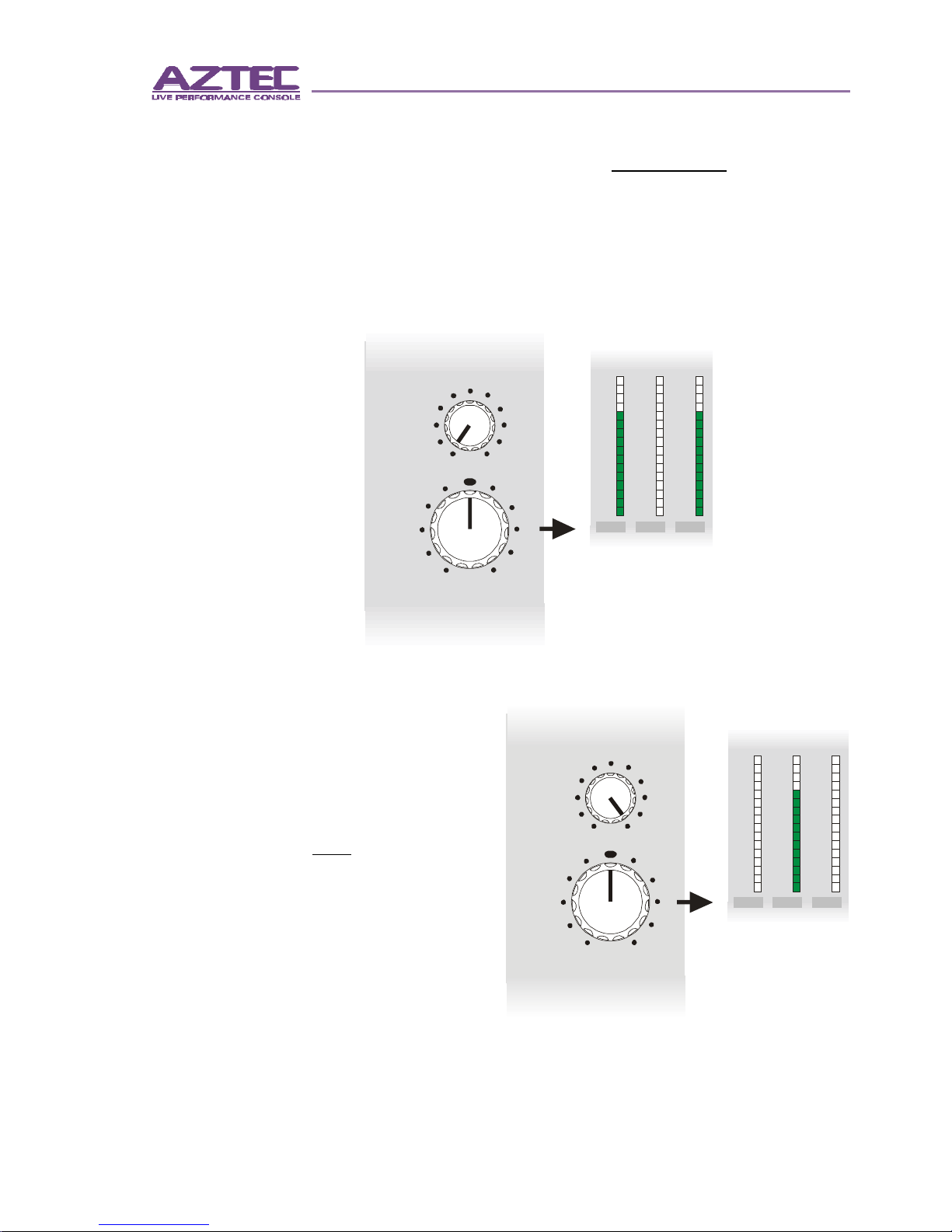
Sub-Group module - MeteringSub-Group module - Metering.................................................................................................... 2828
Sub-Group module - MatrixSub-Group module - Matrix .......................................................................................................... 2929
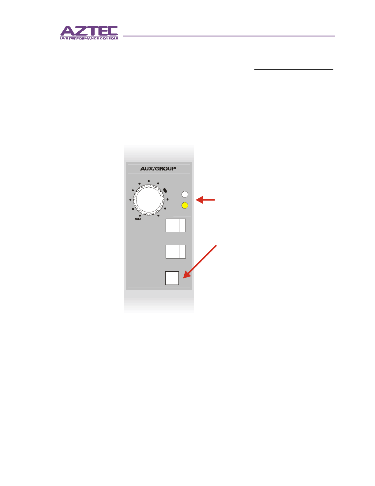
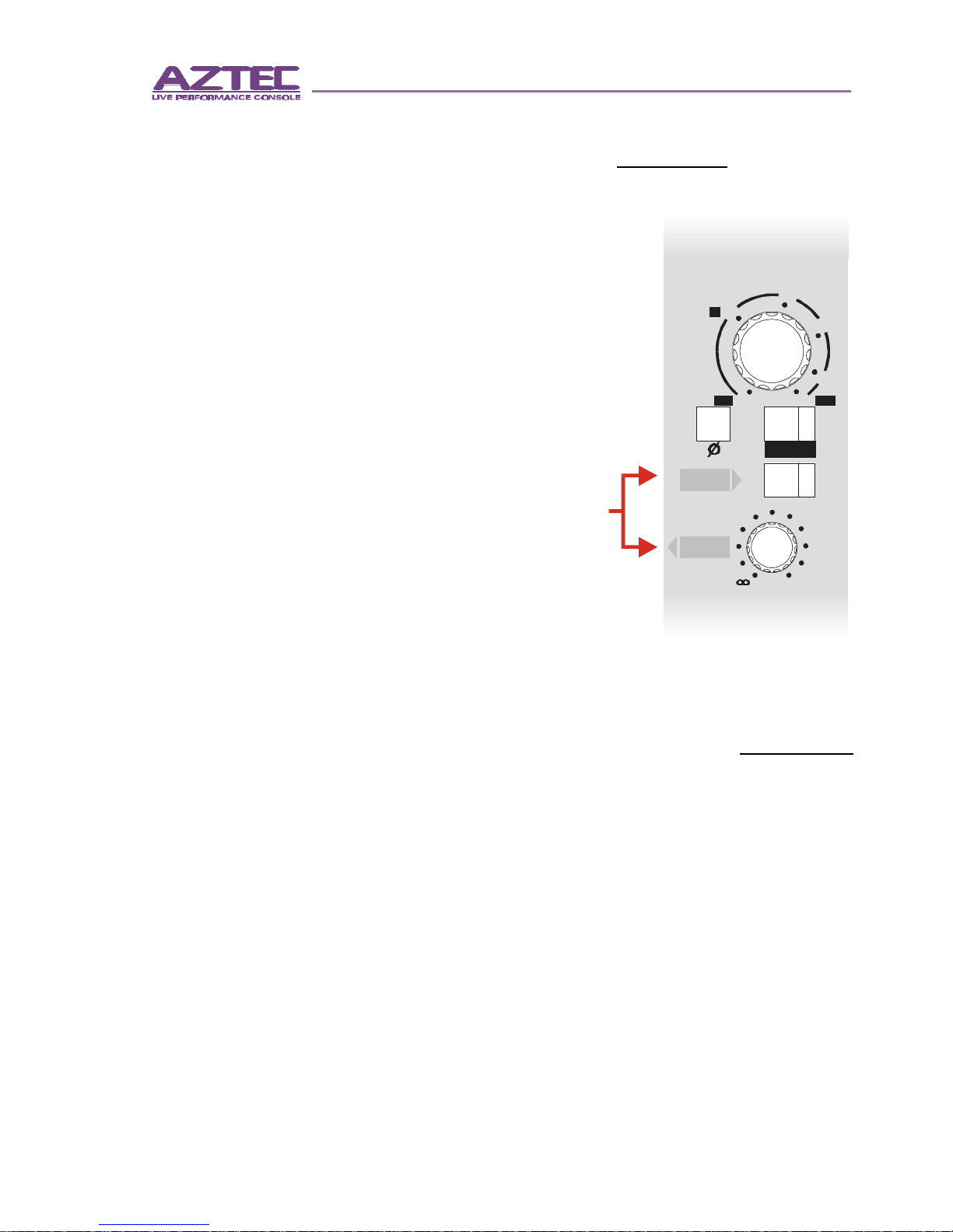
Sub-Group module - Aux and Group MastersSub-Group module - Aux and Group Masters .................................................... 3030
Stereo Auxiliary module - Meter Select and PSU statusStereo Auxiliary module - Meter Select and PSU status .......................... 3131
Stereo Auxiliary module - Stereo Input gain and AuxiliariesStereo Auxiliary module - Stereo Input gain and Auxiliaries ............ 3232
Stereo Auxiliary module - Stereo Input routing and faderStereo Auxiliary module - Stereo Input routing and fader ...................... 3333
Stereo Auxiliary module - Stereo Auxiliary MasterStereo Auxiliary module - Stereo Auxiliary Master ........................................ 3434
Master module - Metering, Dimmers and CommsMaster module - Metering, Dimmers and Comms .......................................... 3535
Master module - Comms Assign and SoloMaster module - Comms Assign and Solo ............................................................ 3636
Master module - Monitors, Ambience Input and T/B keyMaster module - Monitors, Ambience Input and T/B key...................... 3737
Master module - Main outputsMaster module - Main outputs .................................................................................................. 3838

4
©audient 6/2002
Systems InterfacesSystems Interfaces
Mono InputMono Input .......................................................................................................................................................... 3939
Sub-Group module connectionsSub-Group module connections .............................................................................................. 4040
Stereo Auxiliary module connectionsStereo Auxiliary module connections ................................................................................ 4141
Master module connectionsMaster module connections .......................................................................................................... 4242
PSU and Link and Automation connectionsPSU and Link and Automation connections .............................................................. 4343
Connector wiring details - Audio connectionsConnector wiring details - Audio connections .................................................. 4444
Connector wiring details - DC connectionsConnector wiring details - DC connections............................................................ 4646
Console LinkingConsole Linking .............................................................................................................................................. 4646
Connector wiring details - Midi connectionsConnector wiring details - Midi connections ...................................................... 4848
Connector wiring details - Data connectionsConnector wiring details - Data connections ...................................................... 4848
Block schematicsBlock schematics
Mono inputMono input .......................................................................................................................................................... 4949
Stereo Return and Ambience inputStereo Return and Ambience input .................................................................................... 5050
Sub-Group and Auxiliary outputsSub-Group and Auxiliary outputs .......................................................................................... 5151
Main outputsMain outputs .................................................................................................................................................... 5252
Matrix and Meter selectMatrix and Meter select ...................................................................................................................... 5353
Talkback, Signal generator and LinkingTalkback, Signal generator and Linking .......................................................................... 5454
AutomationAutomation .......................................................................................................................................................... 5555
Gain structure.........................................................................Gain structure......................................................................... 5656
SpecificationsSpecifications .................................................................................................................................................... 5757
WEIGHTSWEIGHTS ................................................................................................................................................................ 5858
DIMENSIONSDIMENSIONS .................................................................................................................................................... 5858
LAYOUTSLAYOUTS ................................................................................................................................................................ 5959
CleaningCleaning .................................................................................................................................................................. 6060
Removing modulesRemoving modules .................................................................................................................................... 6060
Removing fader blocksRemoving fader blocks .......................................................................................................................... 6161
Removing Connector panelsRemoving Connector panels .......................................................................................................... 6262
PSUPSU ................................................................................................................................................................................ 6262
PSU - continuedPSU - continued ............................................................................................................................................ 6363
WarrantyWarranty.................................................................................................................................................................. 6464

5
IntroductionIntroduction
©audient 6/2002
EARTH This unit is connected via its PSU power cord to the
mains safety earth. NEVER OPERATE THE UNIT
WITH THIS EARTH CONNECTION REMOVED.
COVERS DO NOT remove the covers. Refer servicing to
qualified personnel only.
VOLTAGE CHECK that the correct operating voltage has been
set for your AC mains supply.
FUSES CHECK that the fuse fitted is the correct type for the
mains voltage selected. ALWAYS replace fuse with the
correct type.
MOISTURE DO NOT expose the unit to rain or moisture. If the
Aztec or its PSUs should become so exposed
REMOVE the mains power immediately.
CABLES PROTECT the mains power cord from damage
though impact or abrasion.
HEAT ALWAYS ssite the Aztec and its PSUs away from
sources of heat including direct sunlight and ensure
adequate ventilation around PSUs and around the
ventilation grills on the console .
RISK OF
ELECTRIC SHOCK
DO NOT OPEN
RISQUE DE CHOC
NE PAS ENLEVER
CAUTION ATTENTION
WARNING
THIS EQUIPMENT MUST BE EARTHED
DO NOT EXPOSE TO RAIN OR MOISTURE
IMPORTANT SAFETY INSTRUCTIONSIMPORTANT SAFETY INSTRUCTIONS
Please read all of these instructions and save
them for later reference before attempting to
connect the Aztec PSU to the AC power
source.

6
IntroductionIntroduction
©audient 6/2002
Designed specifically for the discerning sound reinforce-
ment professional, and equally at home on the road or in
a fixed installation, the new Aztec Live Performance
Console rewrites the rules with class leading audio
performance and features, an innovative rugged light-
weight frame structure and remarkable affordability.
Aztec is available in three frame sizes providing 32, 40,
48 and 52 mono inputs, 2 additional stereo line inputs
and a stereo ambience mic input. Console and extender
linking is provided as standard.
The extensive feature set is the result of long experience
combined with the feedback of many respected sound
reinforcement professionals.
•Separate L, C, and R buses with individual trims on
each of the Main output faders.
•12 VCA Sub Groups with VCA Solo.
•8 Audio Sub Group outputs with balanced inserts.
•8 Mono and 2 Stereo Auxiliary outputs with balanced
inserts.
•12 x 8 Matrix with balanced inserts.
•4 band EQ with parametric mids, sweep HF and LF
with switched Bell/Shelf curves plus Sweep Hi-Pass
filter.
•Optional full stereo input modules.
•All inputs and outputs fully balanced ( including
+4dBu Inserts ).
•Mute and VCA assignment automation as standard.
•Midi message output for control of outboard equip
ment.
•Dedicated recorder interfaces for seamless
performance archiving and post-production.
•Extensive peak reading LED metering.
•Flexible monitor outputs for headphones and
engineers wedge.

7
Getting StartedGetting Started
©audient 6/2002
FOH and MonitorsFOH and Monitors
Aztec is configured primarily as a FOH console.
In this default mode the master levels for the 8 mono
Auxiliary sends are set on rotary controls. The two
Stereo Auxiliaries (which would normally be used
for any IEM feeds) along with
the 8 audio Sub-Groups, have
100mm faders for their
master levels
However, when more monitor
sends are required the Master
level controls for each of the
Sub-Group and Auxiliary
outputs may be swapped by
depressing the GRP/AUX
swap buttons on each Sub-
Group output module. The
function of the rotary control
and fader are shown by the
LED adjacent to each. The
Solo and Mute functions
swap with the level control
but output connections are
unaffected.
MASTER
SOLO
SOLO
GRP/AUX
SWAP
MUTE
0
+6
AUX
GRP
dB
RecordingRecording
Recognising the increasing requirement to record per-
formances, Aztec is unique amongst large format Live
performance consoles in providing dedicated record and
remix functions.

8
Getting StartedGetting Started
©audient 6/2002
D-OUT
D-IN
dB 0
10 30
20
40
0-10
0
2560
dB
GAIN
LINE
The provision of the fully
balanced D-IN ‘remix’ input,
again on D-Sub connectors
in groups of 8, allows Aztec
to be used for post-produc-
tion of recorded perform-
ances preserving EQ and FX
configurations used in the
original show.
Audio Sub-Group outputs
are available on a D-sub
connector as well as XLRs, for rapid
recorder connection if required.
Using LCRUsing LCR
A fully balanced, level
variable direct record out is
available on jack and, in
groups of 8 channels, on D-
sub connectors wired in
accordance with Tascam
DA98 format. This allows
simple connection to one or
more 8 track recorders.
RecordingRecording (continued)
The Aztec LCR MAIN output bus routing system uses
two controls - a Left/Right pan control and a Blend
control. This allows a centre cluster to be used to ‘an-
chor’ a lead vocalist while still feeding the main Left/
Right stacks to ensure adequate coverage.
The pan operates in the normal way with a constant-
power law. The Blend control adjusts the proportion of
the signal sent to the Left/Right buses and the Centre
bus.

9
Getting StartedGetting Started
©audient 6/2002
With Blend in the fully counter-clockwise position rout-
ing (and panning) is conventional Left and Right with no
signal sent to the Centre bus.
With Blend set in
the fully clock-
wise position
only the Centre
bus is fed.
With Blend at 12
o’clock all three
buses are active.
RL
CLR
BLEND
PAN
RIGHTCENTRELEFT
+15+15+15 +18+18+18 +21+21+21
+12+12+12 +9+9+9
+6+6+6 +3+3+3 000 -3-3-3
-6-6-6 -9-9-9
-12 -12 -12
-18 -18 -18
-24 -24 -24
-30 -30 -30
-36 -36 -36
RL
CLR
BLEND
PAN RIGHTCENTRELEFT
+15+15+15
+18+18+18
+21+21+21
+12+12+12
+9+9+9
+6+6+6
+3+3+3
000
-3-3-3
-6-6-6
-9-9-9
-12 -12 -12
-18 -18 -18
-24 -24 -24
-30 -30 -30
-36 -36 -36
Using LCRUsing LCR (continued)

10
Getting StartedGetting Started
©audient 6/2002
MutesMutes
All Mutes on the Aztec control surface with the excep-
tion of those for the three Main outputs are under
central control. They can therefore be operated either by
the Scene Automation system or locally by depressing
the relevant physical Mute button. Local operation
always has priority. Mutes operate (or release) on the
button down-press. To isolate the Mute from central
control depress the channel SAFE key
SolosSolos
Aztec is equipped with a multi-function Solo System.
Three main modes are provided, PFL, AFL and
Solo-in-place. These modes are set from the Master
Module. Default mode is PFL, AFL is
selected by depressing the AFL button.
VCA Solos are also provided and these
are explained in the ‘VCA Masters’
section. Solo-in-place mode can only
be invoked by pressing and holding the
large illuminated SIP button down for
>3 seconds. In this mode all channels
other than the one Solo’d and those
with Safe selected will be muted.
Solo button behaviour is dependant on
press duration. A short press provides
the usual latch-on, latch-off action.
Depressing a Solo for > 2 seconds
provides momentary operation - the Solo clears on
button release.
dB
0
+10-10
LEVEL
ADD AFL
CLEAR
SOLO
I/P
0/P
SIP

11
Getting StartedGetting Started
©audient 6/2002
Multiple Solos may be selected by setting the system to
ADD mode. Active Solos can be cleared by a single
press of the CLEAR button.
Input Solos and Output Solos have separate indicator
LEDs and Input Solos are arranged so as to (temporarily)
over-ride Output Solos.
Solo levels can be gain adjusted by +/- 10dB and are
automatically monitored on both the Main Monitor and
on the Headphones systems but automatic switching
can be disabled for either by depressing the Solo OFF
buttons in the Master module monitor sections.
Solo’d AFL signals are metered on the L, C. R Master
module LED bargraph displays. PFL has a dedicated
bargraph display.
PFLRIGHTCENTRELEFT
+15
+18
+21
+12
+9
+6
+3
0
-3
-6
-9
-12
-18
-24
-30
-36
+15
+18
+21
+12
+9
+6
+3
0
-3
-6
-9
-12
-18
-24
-30
-36
+15
+18
+21
+12
+9
+6
+3
0
-3
-6
-9
-12
-18
-24
-30
-36
+15
+18
+21
+12
+9
+6
+3
0
-3
-6
-9
-12
-18
-24
-30
-36
SolosSolos (continued)

12
Getting StartedGetting Started
©audient 6/2002
Assigning VCAsAssigning VCAs
Each Aztec Input channel can be assigned to any or all
of the 12 VCA Sub-Groups using the Assignment keys
on the Central Control panel and the SET key adjacent to
the channel fader.
Pressing any of the VCA assignment keys enables
assignment mode.
The VCA selection set using these keys can then be
loaded to input channels by depressing the channel set
key(s).
The stored assignment is displayed on the column of 12
LEDs adjacent to each channel fader.
VCA
SET
VCA ASSIGN
CENTRAL CONTROL PANEL CH FADER
SET KEY
SAFE KEY
VCA ASSIGNMENT
KEYS
VCA ASSIGNMENT
INDICATORS
SAFE

13
Getting StartedGetting Started
©audient 6/2002
Assigning VCAsAssigning VCAs (continued)
Assignment mode times-out if no key pushes are made
for 1 minute.
To clear a stored VCA assignment depress VCA
assignment key 1 to enter Assignment mode, press it
again to clear the assignment then finally press the
channel set key to clear the channel settings .
Individual channels may be completely isolated from the
Central Control commands by pressing the SAFE key.
To set:To set: {VCA assignment key(s)}{Channel set key}{VCA assignment key(s)}{Channel set key}
To clear:To clear: {VCA assignment key 1 x 2}{Channel set key}{VCA assignment key 1 x 2}{Channel set key}
Assigning channels to VCA Sub-Groups:Assigning channels to VCA Sub-Groups:

14
Getting StartedGetting Started
©audient 6/2002
The VCA MastersThe VCA Masters
The 12 VCA master faders are fitted centrally in the
console fader section below the audio Sub-Group out-
put modules. Each VCA master fader has an associated
Mute and Solo switch.
The central control of the VCA assignment and Mute
operation has enabled full VCA Solo functionality to be
provided.
Selecting a VCA Master Solo key will automatically Solo
all input channels assigned to that VCA Master.
10 10 10
0 0 0
5 5 5
5 5 5
10 10 10
20 20 20
30 30 30
40 40 40
50 50 50
70 70 70
MUTE MUTE
SOLO SOLO

15
Getting StartedGetting Started
©audient 6/2002
Automation - OverviewAutomation - Overview
Aztec Automation stores VCA assignments and Mute
status in any of 999 ‘Scene’ memory locations. These
can then be recalled either sequentially using the NEXT
(or LAST) keys or randomly using the UP⇑ and DOWN⇓
keys (followed by the NOW key).
Up to 9 additional
Scenes may be
inserted between
two existing
locations.
Scenes may be
previewed
sequentially by
pressing PRV and
then using the NEXT
and LAST keys or
randomly using the
UP⇑ and DOWN⇓
keys. A previewed
scene can be loaded
by simply pressing
the NOW key.
Whether stored as a
Scene or not the
control surface
status is stored every
~ 10 seconds. The
latest stored settings
before a power-
down are
recalled after power-
up.
Each block of 8 input
channel faders, the
VCA Master fader
block and the Central Control panel are provided with
Isolate switches to enable continued working in the
event of a partial failure. These switches are located
under the armrest on the front surface of the console
behind black cover plugs. Push the switches to isolate.
QUICK SCENES
UP
DOWN
PRV
NOW NEXT
INS DEL
LAST
STO
ACTIVE STORED
CENTRAL CONTROL PANEL

16
Getting StartedGetting Started
©audient 6/2002
Automation - Storing ScenesAutomation - Storing Scenes
Pressing the STO (Store) key will copy the current con-
sole surface VCA assignments and Mute status into a
memory at the displayed Scene number for later recall.
The displayed
Scene number
can be se-
lected using
the UP⇑ and
DOWN⇓ keys.
If the Scene
number
chosen is
already used
the STO key
will flash and
the right-hand
decimal point
indicator in
the display
will be lit.
To over-write the existing stored Scene depress STO
and hold it down for ~ 2 seconds until the display stops
flashing.
To insert a Scene between two existing Scenes press
the INS (insert) key and then the UP⇑/DOWN⇓keys to
select one of the 9 Sub-Scenes (nnn.1 to nnn.9) and
then press STO.
When scrolling through Scenes using the UP⇑/DOWN⇓
keys the currently active Scene is indicated by illumina-
tion of the left-hand decimal point indicator in the dis-
play.
UP
DOWN
PRV
NOW NEXT
INS DEL
LAST
STO
ACTIVE STORED
Storing Scenes:Storing Scenes:
{{⇑⇓ }{STO}}{STO} Stores to the selected SceneStores to the selected Scene
{{⇑⇓}{STO 2s}}{STO 2s} Overwrites the selected SceneOverwrites the selected Scene
{{⇑⇓ }{INS} {}{INS} {⇑⇓ }{STO}}{STO} Inserts a Sub-SceneInserts a Sub-Scene

17
Getting StartedGetting Started
©audient 6/2002
{NEXT}{NEXT} Recalls the next stored SceneRecalls the next stored Scene
{LAST}{LAST} Recalls the previous stored SceneRecalls the previous stored Scene
{{⇑⇓}{NOW}}{NOW} Recalls the displayed SceneRecalls the displayed Scene
Automation - Recalling ScenesAutomation - Recalling Scenes
The LAST, NEXT and NOW keys allow stored Scenes to
be recalled easily and quickly. The LAST and NEXT keys
recall Scenes in numerical order with unused locations
being skipped.
To recall a specific Scene (out of sequence) use the UP⇑/
DOWN⇓ keys to select the required Scene and then
press NOW to recall it. When scrolling through Scene
memories in this way the scroll speed will increase if the
UP⇑/DOWN⇓ keys are held down. Unused locations are
again skipped and the currently active Scene is indicated
by illumination of the left-hand decimal point indicator in
the display.
Automation - Previewing ScenesAutomation - Previewing Scenes
Pressing the PRV (Preview) key puts the automation
system into Preview mode. The PRV key flashes to
indicate this. The LAST, NEXT and UP⇑/DOWN⇓ keys
can then be used to preview Scene stores without
loading the stored assignments. The Previewed Scene
can be edited in this mode and re-stored. To make the
Previewed Scene active and exit Preview mode press
the NOW key.
Recalling Scenes:Recalling Scenes:

18
Getting StartedGetting Started
©audient 6/2002
Automation - Deleting ScenesAutomation - Deleting Scenes
Holding down the DEL (Delete) key for 4 seconds clears the displayed
scene store.
To clear all stores ready for a new show hold down the NOW key for 4
seconds, the DEL key for 4 seconds and then the NOW key again for a
further 4 seconds.
Deleting Scenes:Deleting Scenes:
{{⇑ ⇓⇑ ⇓ }{DEL 4s}}{DEL 4s} Clears the displayed SceneClears the displayed Scene
{{NOW 4s}{DEL 4s}{NOW 4s}NOW 4s}{DEL 4s}{NOW 4s} Clears all Scene memoriesClears all Scene memories
Previewing Scenes:Previewing Scenes:
{PRV}{{PRV}{⇑ ⇓}{PRV}}{PRV} Previews the displayed scenePreviews the displayed scene
{PRV}{NEXT}{PRV}{NEXT} Previews the next stored scenePreviews the next stored scene
{PRV}{NEXT}{NOW}{PRV}{NEXT}{NOW} Previews the next stored scene andPreviews the next stored scene and
then makes it active.then makes it active.
Automation - Previewing ScenesAutomation - Previewing Scenes (cont)

19
Getting StartedGetting Started
©audient 6/2002
Automation - Using Quick ScenesAutomation - Using Quick Scenes
QUICK SCENES
8 Quick Scenes keys can be allocated
to any numerical Scene numbers to
provide quick access to the next
major assignment. Pressing and
holding a Quick Scene key for ~2
seconds until it starts flashing will
assign the currently displayed Scene
number to that Quick Scene key.
To recall the Scene assigned to the
Quick Scene key simply depress that
key.
Quick Scene assignments can be
deleted by pressing the Quick Scene
Key and then depressing it again for
~ 2seconds. Note that this action
deletes only the Quick scene assign-
ment and not the numerically stored
Scene.
{QUICK SCENE 1-8 }{QUICK SCENE 1-8 } Recalls the Scene asRecalls the Scene as signed tosigned to
the Quick Scene keythe Quick Scene key
{QUICK SCENE 1-8} QUICK SCENE 1-8 2secs}{QUICK SCENE 1-8} QUICK SCENE 1-8 2secs} Deletes the QuickDeletes the Quick
SceneScene
{{⇑ ⇓⇑ ⇓ }QUICK SCENE 1-8 2s}}QUICK SCENE 1-8 2s} Assigns the selectedAssigns the selected Scene to theScene to the
selected QUICK SCENEselected QUICK SCENE
Quick Scenes:Quick Scenes:

20
Getting StartedGetting Started
©audient 6/2002
MidiMidi
UP
DOWN
PRV
NOW NEXT
INS DEL
LAST
STO
ACTIVE STORED
MIDIMIDI
Each Aztec Input channel is represented by MIDI notes
1-48.
To set up MIDI messaging first select the required Scene
number (it is not necessary to make the scene active).
Now depress and hold the illuminated key at the front
right of the Automation Control Panel (the MIDI key)
until it illuminates. The 7-segment display will now be
blank. Then, to view or edit midi
message settings, depress the
SET switch on the relevant
Aztec Input channel. The active
MIDI channel number (0-15) is
shown in the 7-segment
display and this can be
modified using the UP⇑ and
DOWN⇓ keys.
Once the MIDI channel number
has been selected, depressing
the Input channel SET key will
toggle the MIDI message from
NOTE ON to NOTE OFF to no
message to NOTE ON again.
The NOTE setting is shown by
the status of channel VCA
Assignment indicator LEDs.
NOTE ON being indicated by
LEDs 1/2 flashing, NOTE OFF
by LEDS 11/12 flashing.
VCA
SET
CH FADER
SET KEY
VCA ASSIGNMENT
INDICATORS
Table of contents
Other Audient Dj Equipment manuals