Audio Control SA-3051 User manual
SA-3051 and SA-3052
Spectrum Analyzer
One-Third-OcTave real Time analyzer
WiTh memOries and digiTal sPl disPlay
Operation Manual
22410 70th Avenue West • Mountlake Terrace, WA 98043 • Phone 425-775-8461 Fax 425-778-3166
www.audiocontrol.com P/N 9130430
© 1997 All Rights Reserved

SA-3051/SA-3052 Operation Manual

About This Manual .............................................................. i
Notational Conventions ....................................................... i
Notes, Cautions, and Warnings ............................................ i
Chapter 1 Introduction
Test Instruments vs. Toys................................................. 1-1
ANSI Filter Design .......................................................... 1-2
Applications ..................................................................... 1-3
Accessory Information..................................................... 1-3
Chapter 2 SA-3051/SA-3052 Front and Rear Panel Features
Front Panel ....................................................................... 2-1
Rear Panel ........................................................................ 2-4
Chapter 3 Operation
Quick-Start Information................................................... 3-1
Using The SA-3051/SA-3052's Functions....................... 3-1
Storing a Response Curve................................................ 3-1
Recalling a Response Curve ............................................ 3-1
Averaging Several Readings ............................................ 3-2
Peak-Hold ........................................................................ 3-2
Peak-Hold Digital SPL..................................................... 3-2
Exercising Your Options .................................................. 3-2
Printer Operation.............................................................. 3-2
Printers Supported............................................................ 3-2
Connector Pin Designations............................................. 3-4
Battery Operation............................................................. 3-4
A and C Weighted Measurements .................................... 3-5
Getting extreme at 175dB SPL ........................................ 3-6
Chapter 4 Acoustical Testing with the SA-3051/SA-3052
Overview.......................................................................... 4-1
Basic Procedure ............................................................... 4-2
Body Effects..................................................................... 4-3
Sound Pressure Level and Hearing Loss ......................... 4-3
Chapter 5 SA-3051/SA-3052 Applications
Sound System Equalization ............................................. 5-1
Hi-Fi Equalization............................................................ 5-1
Multi-Channel/THX Equalization ................................... 5-2
Sound System Equalization ............................................. 5-4
Monitor Speaker Equalization ......................................... 5-4
Fold Back Monitor Equalization...................................... 5-5
Feedback tuning ............................................................... 5-5
Pink noise equalization and feedback tuning................... 5-5
Component Checkout....................................................... 5-6
Tape Machine Alignment ................................................. 5-8
Sound and Music Monitoring .......................................... 5-8
Crossover Testing............................................................. 5-9
Chapter 6 Theory of Operation
Input Circuitry ................................................................. 6-1
One-Third Octave Filters ................................................. 6-1
Signal Multiplexing and Analog to Digital Conversion .. 6-1
Microprocessor Circuitry ................................................. 6-2
LED Display .................................................................... 6-2
Pink Noise Generator....................................................... 6-2
Chapter 7 Warranty
Legalese .......................................................................... 7-1
Service Information ......................................................... 7-2
Chapter 8 Specications
Table of Contents

SA-3051/SA-3052 Operation Manual

About This Manual
This manual describes the AudioControl Industrial SA-3051/SA-3052 and a few of its audio applications.
The manual is divided into several major sections.
Section 1. Introduction is an introduction to the SA-3051/SA-3052 and to this manual.
Section 2. SA-3051/SA-3052 Front and Rear Panel Features describes the physical features found on
the front and rear panels of the SA-3051/SA-3052.
Section 3. Operation describes how to use the various functions of the SA-3051/SA-3052
Section 4. Acoustical Testing with the SA-3051/SA-3052 has procedures for using the SA-3051/SA-3052
for sound system equalization and analysis.
Section 5. SA-3051/SA-3052 Applications describes a few other applications for the SA-3051/SA-3052
besides equalizing sound systems.
Section 6. Theory of Operation, for terminally curious technoids only, is a description of what goes on
insidetheconnesofthebox.
Section 7. Warranty Information describes the SA-3051/SA-3052 warranty and tells how to obtain
service for the SA-3051/SA-3052. We trust that you'll never need to use this section.
Section 8. SpecicationsliststheSA-3051/SA-3052'sspecications.
Notational Conventions
Within this manual, several different notation conventions are used to indicate various facets of the
SA-3051/SA-3052's features.
Small CapS Indicate a marked feature on the unit, like the control or the connector. They are
also used within procedures to identify controls and switches by function.
Italics and boldface Are used for emphasis. Words printed in boldface convey more emphasis than
those printed in italics.
Notes, Cautions, and Warnings
Some of the text in this manual is set apart by the headings: Note, Caution, or Warning.
These terms are used to denote varying degrees of awareness required by the user during installation,
operation, or maintenance of the SA-3051/SA-3052.
NOTE conveys information that may be helpful to the user. A note is similar to an aside
during a conversation.
CAUTION indicates a potential danger to the instrument.
WARNING indicates a potential hazard to the operator.
About this Manual
i
© 1997 AudioControl. All rights reserved.

SA-3051/SA-3052 Operation Manual

Introduction
Congratulations on purchasing one of the world's most popular audio analyzers. The AudioControl Indus-
trial SA-3051/SA-3052 is an affordable, measurement-grade, one-third octave real-time analyzer de-
signed for audio signal analysis. Previous analyzer designs were either too costly for the average profes-
sional or too inaccurate for serious use. The SA-3051/SA-3052 overcomes these inadequacies by combin-
ing a state-of-the-art microprocessor-based design with modern electronic manufacturing techniques. The
result is a very accurate, quick and easy to use instrument, self contained in one box.
The SA-3051/SA-3052 includes the following features:
•30one-thirdoctavebandwidthlters
•Fourth-orderltersconformtoANSIS1.11-1986standards
• Laboratory-grade calibrated measurement microphone
• Internal digital pink noise source
• 32 dB display window
• 9 x 30 large-format LED display matrix
• Full-screen digital SPL readout with 1/10th dB resolution
• Six non-volatile memories with lithium battery backup
• Frequency response averaging for up to six stored response curves
• 20 second temporal averaging
• Peak-hold
• Balanced XLR microphone, balanced TRS ¼" phone jack and unbalanced RCA connector inputs
• 175dB sound pressure level measurement (optional)
•A-andC-weightinglter(optional)
• Portable battery operation (SA-3052)
• Parallel printer port (SA-3052)
Test Instruments vs. Toys
There is a fundamental difference between the many real-time analyzers currently available on the market
today. That difference is one of calibration. An instrument that is calibrated is capable of making mea-
surements based on some absolute reference (absolute measurement).
An instrument that isn't calibrated can only make comparisons against a relative reference (relative
measurement). For example, someone asks you, "How hot is it today?" If you step outside for a moment
and reply, "Oh, a bit hotter than yesterday," that's a relative measurement. On the other hand, if you step
outsideandconsultacertiedlaboratorythermometerandsay"85degreesF,"you'vemadeameasure-
ment against an absolute reference.
TheSA-3051/SA-3052wascalibratedatthefactorytomeetorexceeditspublishedspecications.You
can make a measurement with the SA-3051/SA-3052 and compare it with a measurement made by any
other measurement-grade instrument and know that you are comparing apples with apples.
1-1

SA-3051/SA-3052 Operation Manual
ANSI Filter Design
A real-time analyzer works by dividing the audio spectrum up into equal bandwidth parts using a set of
calibrated(usually)bandpasslters.Thentheoutputofeachlterisdisplayedonsomesortoflevelindi-
cator: LED matrix, Video display, LCD, etc.
The American National Standards Institute (ANSI) oversees the establishment and maintenance of vari-
ous engineering standards in conjunction with the International Standards Organization (ISO) in Europe.
Thesetwostandardsorganizationshaveestablishedstandardsfortheperformanceofthebandpasslters
used for acoustical measurement purposes.
Forone-thirdoctaveanalyzers,therearetwoclassesofltersallowedbyANSI.TheseareClassII,and
ClassIII.ClassIisreservedforoctavebandwidthanalyzers.ClassIIIltersarethehardesttodesign
and manufacture and are usually only found on the most expensive (read unaffordable) analyzers. Class
IIlters,areeasier(noteasy,justeasier)todesignandmanufacturethanClassIIIlters.Anyreal-time
analyzerintendedforseriousmeasurementworkwilluseltersthatatleastmeetClassIIstandards.
TheltersusedintheSA-3051/SA-3052analyzermeetorexceedthestandardsspeciedbyANSIfora
ClassII,TypeElterset.
Figures1.1and1.2showtwodifferentone-thirdoctavelters.Figure1.1isrepresentativeofthosefound
inmostlower-costanalyzers.Figure1.2isanactuallterusedintheSA-3051/SA-3052.Notethedif-
ferenceintheresponseawayfromthecenterfrequency.Theinferiorlter'sbroadresponsecharacteristic
translates to potential measurement errors at frequencies removed from the band-center and undesirable
interaction between adjacent frequency bands.
Figure 1.1. A non-measurement quality one-third octave lter
Figure 1.2. A measurement quality one-third octave lter
1-2

Applications
The SA-3051/SA-3052 is well-suited to many audio applications including but not limited to:
• Acoustical analysis for sound reinforcement or recording studios
• Movie theater system setup and projector alignment
•Fastfrequencyresponsemeasurementsonampliers,taperecorders,equalizers,etc.
• Tape recorder setup
• Industrial noise measurement
Accessory Information
Model Description
RM-10 Heavy steel 19-inch rack mount adapter. Requires 3 rack spaces (5.25 inches)
BP-10 Rechargeable internal battery system (SA-3052)
PI-10 PC compatible, parallel printer output port (SA-3052)
CP-10 Adds owner’s name to PI-10 printout
SPL-175 175 dB SPL measurement upgrade
AC-10 Plug-inA-andC-weightinglter
SC-10 Soft carrying case. Includes space for analyzer, mike and cables (SA-3052)
Note: The SPL-175, BP-10, PI-10, and CP-10 options must be installed by the factory.
BP-10 Rechargeable Internal Battery Pack
The rechargeable battery option allows the SA-3052 to be used independent of AC mains power. The
batteries install within the instrument and provide up to 4 hours of operation on a full charge.
The batteries are recharged by plugging the instrument into a source of AC mains power and leaving
the front panel Power switch set to off for a period of 9 to 10 hours.
PI-10 Printer Output
The printer output option provides a Centronics parallel interface for a PC compatible printer (not pro-
vided). The analyzer-to-printer cable is a standard PC-type parallel printer cable (also not provided).
The printed output is a form with suitable blank spaces for recording the time and place of the mea-
surement and other data, followed by the a printed representation of the real-time spectrum display on
the analyzer.
CP-10 Customized Printout
The CP-10 option customizes the printer output form to include six lines of data for your business
name, address, and other data. Since this data is onlyfactoryinstalled,ithastheadditionalbenetof
“branding” your analyzer in case someone wanders off with your prize analyzer. You must have the
PI-10 printer option installed before you can add the CP-10.
SC-10 Soft Carrying Case
The soft carrying case protects the SA-3052 from the ravages of portable operation. It includes a large
pocket to carry the mike and cables. There is also a hatch on the bottom of the case to allow access to
the power cord connection.
AC-10 A- and C-weighting Filter
TheAC-10A/Cweightinglterisacompactplug-inmoduledesignedtobeinsertedinlinewiththe
microphone. The AC-10 applies the standard A- or C-weighting function to the microphone signal.
SPL-175 High SPL option
The SPL-175 option allows sound pressure level measurements up to 175dB. The SPL-175 includes a
high SPL microphone and software upgrades.
1-3
Introduction

SA-3051/SA-3052 Operation Manual

SA-3051/SA-3052
Front and Rear Panel Features
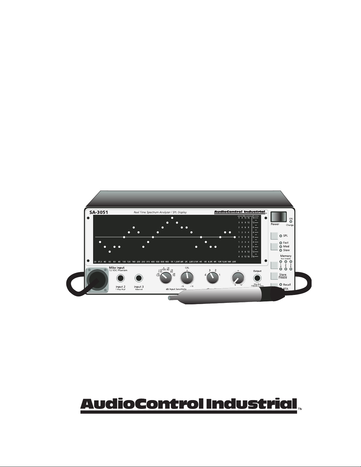
Figure 2.1. SA-3051/SA-3052 Front Panel with digital SPL readout
Front Panel
lED DiSplay
The left portion of the display shows the one-third octave energy content of the input signal from 25 Hz
to 20kHz. Each column within the display represents one one-third octave band. The band centers are
marked on the bottom of the screen.
The right-hand end of the display indicates the setting of the DBswitch, and consequently the amount of
change in the input signal that each LED on the left- hand side of the display represents.
The far right portion of the display indicates the sound pressure level (SPL), relative to the settings of the
DBswitch and control.
powEr SwitCh
Depressing the powEr switch to the right turns the SA-3051/SA-3052 on. Pressing it to the left turns it
off.
low Batt/powEr lED
The low Batt/powEr indicator illuminates solid green during normal operation of the
SA-3052.WhenoperatingtheSA-3052ontheoptionalinternalrechargeablebatteries,aashinggreen
LEDindicatesthatthebatteriesneedrecharging.OncetheLowBattLEDhasbegunashing,thereisap-
proximately ½ hour of battery life remaining.
The SA-3052 has a sense circuit that prevents operation of the instrument below critical battery cell volt-
age. This prevents total battery discharge, which shortens the cell life.
To continue operation, the SA-3052 may be operated from the AC power line. The batteries may be re-
charged by plugging the SA-3052 into a suitable source of AC power, with the front panel powEr switch
set to the off position for a period of 9 to 10 hours. The power LED will glow red while the batteries are
chargingandashoccasionallywhenfullycharged.Theminimumrechargetimefromthevoltage-cutout
state is around 2 hours, which will then operate the instrument for around one hour. Completely recharg-
ing the batteries from a discharged state (instrument dead) requires 9 to 10 hours (2 times the discharge
time).
SPL
Momentarily pressing the Spl push-button switch toggles the SPL bargraph at the right side of the
display window on and off. Pressing and holding the SPL push-button activates the full-screen digital
SPL display. Momentarily pressing the SPL switch again restores normal analyzer operation. The associ-
ated LED indicator indicates the status of the SPL switch. The SPL bargraph display scaling is always
4 dB/step, regardless of the setting of the dB switch. The SPL switch works regardless of the setting of
the rECall/rta switch. This means that you can switch the SPL bargraph on and off even with a stored
display.
Features
2-1

SA-3051/SA-3052 Operation Manual
DiSplay SpEED
The display speed push-button switch is located underneath the SPL switch and to the left of the faSt,
mED and Slow LEDs.
The lighted LEDs to the right of the switch indicate the response time of the display. Press the button to
change the decay time of the display. The Fast setting is optimized for looking at transients, the Med set-
ting is useful for program monitoring, and the Slow setting averages 20 samples over a ½ second period.
This works well for measurements using pink noise. A fourth display speed is a 20 second time average.
It is indicated by the SlowLEDashing.Duringtherst20secondsastheaverageisaccumulating,the
SlowLEDwillash2timespersecond.Oncetheaccumulatorisfull,theashingwillslowdownto1
ashpersecond.
mEmory
The SA-3051/SA-3052 can store up to six different frequency response curves (including the SPL dis-
play) in its internal non-volatile memory. These memories are stored at the highest resolution of the SA-
3051/SA-3052, so you can scale the display with the DB/StEp switch during memory recall. Any com-
bination of the memories can also be averaged. Look in the Operation section of this manual for further
information.
An internal back-up battery maintains the contents of the memory for periods of up to one year, even with
the AC power supply disconnected. This feature allows the unit to “remember” a standard curve that may
be recalled each time that the SA-3051/SA-3052 is used.
pink noiSE
The internal pink-noise generator is an accurate, digital, laboratory-grade test source. The pink noise out-
put is accurate throughout the measurement range to within 0.25dB.
The maximum output provided at the ¼" tip-sleeve phone jack is 1 volt into a 600 load (unbalanced, ring
and sleeve grounded), or 150 mW into a 4 ohm load.
The signal level at this connector is controlled by the knob to its immediate left.
Thepinknoisegeneratorhassufcientoutputtodrivevirtuallyanyspeakerorcrossoverdirectly.
DB pEr StEp
This switch sets the resolution of the spectrum analyzer portion of the display. The setting represents the
value of each LED in the display. Thus, a setting of 1dB per step causes each LED in the display to rep-
resent a 1dB change. At this setting, the overall range of the display is 9dB. At the 4-dB-per-step setting,
each LED in the display represents a change of 4dB, with a 36dB overall display range.
When using the SA-3051/SA-3052 for sound system equalization, start with the 4 dB/step setting and
progressively decrease the setting of the DB pEr StEp switch as the equalization process progresses. For
program monitoring, the 4dB position works well because it displays the widest dynamic range.
Memorized response curves are always stored at 1-dB-per-step-resolution, regardless of the setting of the
front panel switch. You can select whatever resolution you wish for a stored display when it is displayed
and know that it is accurate. The same holds true for displays dumped to the printer output.
2-2
CAUTION: A microphone with an unbalanced output may be damaged if connected to this input.
CAUTION: AudioControl Industrial assumes no responsibility for microphones damaged in this
CAUTION: manner. Connect microphones with ¼" phone plug connectors to the Balanced Input 3
CAUTION: connector.
DB input SEnSitivity
The DB input SEnSitivity control and switch select the reference level of the curve shown in the display
window.Thecontroltotherightoftheinputselectorswitchisaneadjustmentandalterstherange
selected by the switch over a range of ±10 dB. The normal setting for this control is the detented (click-
stopped) center position.
The reference level of the display is shown on the display window by the light gray horizontal line. The
actual reference level of the reference line corresponds to the dB level setting of the DBm/Spl switch.
For example, the DBm/Spl switch (coarse adjustment) is set to 90dB. The light gray line on the display
window represents a sound pressure level of 90dB if the 10dB control(neadjustment)issetatthecen-
ter-detented position.
input 3
A ¼" tip-ring-sleeve phone jack is used for connecting to balanced and unbalanced sources. Connect
unbalanced sources by using a tip-sleeve (2 conductor) plug inserted into this jack.
This input has an impedance of 10 kohms and is suitable for signal levels from -56dBu to +36dBu. An
input signal of 0dBu represents 100dB SPL.
input 2
This is a standard audio (RCA) connector with an input impedance of 1 Mohm in parallel with 30 pF. The
particular combination of resistance and capacitance allows connecting a standard oscilloscope probe to
this input.
This input is suitable for signal levels from -56dBu to +36dBu. An input signal of 0dBu represents
100dBSPL.
input 1
This is a standard +12 volt, phantom-powered, balanced microphone input. The phantom power supply is
intended for the AudioControl Industrial CM-10 or SPL-175 measurement microphones.
Ordinary dynamic microphones may also be connected directly to this input providing that they have a
balanced output. Unbalanced microphones may not be used. This input is suitable for acoustical levels at
the microphone ranging from 44dB SPL to 136dB SPL. The SPL display is only accurate if the
AudioControl Industrial CM-10 microphone is used, or if the external microphone matches the sensitivity
of the CM-10 microphone.
Features
2-3
SA-3051/SA-3052 Operation Manual
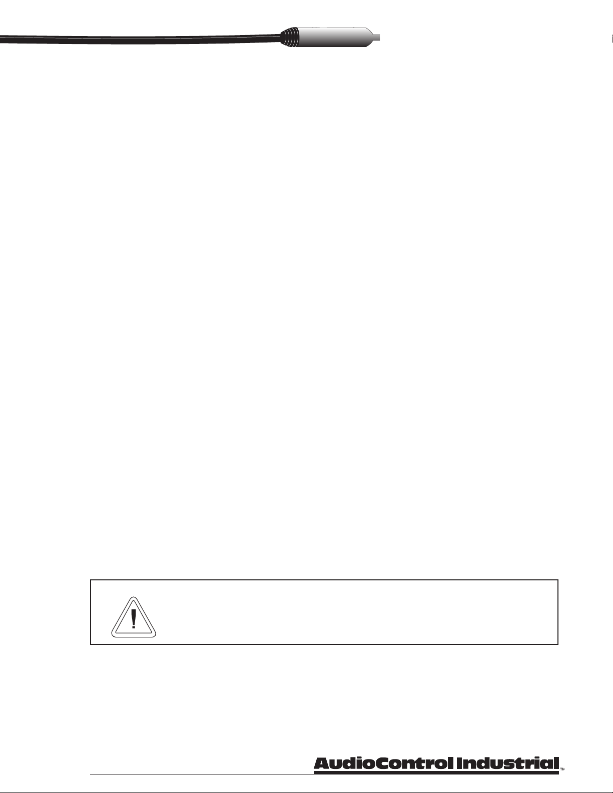
Rear Panel
Figure 2.2. SA-3051/SA-3052 Rear Panel
aC mainS powEr input rECEptaClE
An IEC 3-prong receptacle provides the connection for AC power input to the SA-3051/SA-3052.
The SA-3051/SA-3052 is factory supplied to operate at one of the following AC power supply voltages.
Thesuppliedcongurationismarkedontherearpaneloftheunit.ConsulttheAudioControlIndustrial
factory for power supply conversion information.
n120 VAC, 60 Hz
n220-240 VAC, 50/60 Hz
powEr fuSE
The correct fuse is listed as part AC power markings.
printEr intErfaCE (Sa-3052)
This is a female 25-pin connector (DB-25F) used for connection to an external PC-type printer (not
supplied). The connector is wired for a parallel interface printer. (This connector is present only on the
AudioControl Industrial SA-3052 which is equipped with the printer interface option.) A description of
the pin connections can be found on page 3-4.
print (Sa-3052)
This momentary-contact switch is used to print the contents of the display onto an external printer. This
switch is present only on the SA-3052 which is equipped with the printer interface option.
Note
For longest battery life, always leave the SA-3052 plugged into the AC supply when not in use.
There is no danger of overcharging the battery pack.
2-4

Operation
Using the SA-3051/SA-3052 is simple and straightforward. This section describes the basic procedures.
Quick-Start Information
1. Connect the SA-3051/SA-3052 to a suitable source of AC power. If your instrument is equipped with
thebatteryoption,thebatteriesmustbechargedbeforeuse.ThecorrectACpowercongurationis
marked on the rear panel of the instrument.
2. Connect the input signal source to the appropriate input on the front panel of the instrument.
3. If you are using the internal pink noise source, connect the pink noiSE output of the analyzer to the
amplierorsoundsystemlineinput.Thepink noiSEoutputhassufcientpowercapacitytodirectly
drive a loudspeaker to modest levels.
4. Set the DB input switch so that signal peaks reach the upper third of the display. Adjust the DB input
control as needed. If the variable ±10 dB control is centered, then the gray line dividing the display
represents the SPL setting of the DB SwitCh.
5. Select the display resolution using the DB pEr StEp switch. The switch setting represents the value of
each LED in the display. A scale is printed on the right-hand side of the display window.
6. Select the decay time of the display by pressing the push-button switch adjacent to the faSt, mED, or
Slow LEDs. The Fast setting is suitable for viewing transients. The Med setting is suited to signal
monitoring and the Slow setting works well for pink noise measurements.
7. You can determine the sound pressure level at the microphone by pressing and holding the Spl push-
button for one second until the display changes to the digital mode. This will display the sound pres-
sure level in 1/10th dB resolution. The SPL bargraph is always 4dB per step, regardless of the setting
of the DB pEr StEp switch.
Using The SA-3051/SA-3052's Functions
Storing a Response Curve
1. Press the StorE/frEEzE button. The display is now frozen and ready to be stored.
2. Pressing the mEmory button again steps through the six memories in sequence. The display shows the
contents of each memory as it is selected.
3. The rECall and rta LEDs are not illuminated. This indicates that the SA-3051/SA-3052 is ready to
store the display.
4. Pressing the StorE/frEEzE button again stores the contents of the display into the selected memory.
The associated LED indicators display which memory is currently active.
5. The yellow rECall LED illuminates to indicate that you are now in recall mode. You can recall any
other memory for comparison purposes by selecting that memory by repeatedly pressing the Memory
button.
6. Press the rECall/rta button to return to real-time mode.
Recalling a Response Curve
1. Press the rECall/rta button until the rECall LED is illuminated.
2. Press the mEmory push-button to successively view the contents of the six memories.
3. Pressing the rECall/rta button again returns the SA-3051/SA-3052 to the RTA mode.
Operation
3-1

SA-3051/SA-3052 Operation Manual
Averaging Several Readings
The averaging mode allows up to 256 previously stored readings to be averaged together. The averaged
result is stored in memory number six, replacing its contents.
1. Acquire and store up to six response curves.
2. Press and hold the StorE/frEEzE button for one second. The yellow mEmory 6 lEDisnowashing,
indicating the initiation of the averaging mode.
3.SelecttherstmemoryforaveragingusingthemEmory button. Touch the StorE/frEEzE button once.
4. Select the next memory for averaging using the mEmory button. Touch the StorE/frEEzE button once.
Repeatthisstepforeachadditionalmemorytobeaveraged.Youcanweightaspecicmemoryby
selecting it more than once.
5. After selecting the memory locations to be averaged, press and hold the StorE/frEEzE button for one
second. The mEmory 6 lED will come on solid and the average will be displayed on the screen and
written into memory location 6.
6. The contents of memory location 6 are lost when the average is calculated. The result of the averaging
operation is overwritten into memory location 6.
Peak-Hold
The Peak-Hold mode allows you to accumulate the highest peak level in any of the SA-3051/SA-3052's
thirty display bands. This display may be stored in any memory location, averaged, etc.
1. Press and hold the rta/rECall button for one second. The red rta lEDisnowashing,indicating
the peak-hold mode is active. The display now holds the overall peak level for each of the thirty bands.
2. Pressing the rta/rECall button again exits the peak-hold mode.
Peak-Hold Digital SPL
The digital SPL display may also be operated in peak-hold mode.
1. Press and hold the Spl button until the instrument enters digital SPL mode.
2. Press and hold the rECall/rta button until the Spl lEDstartsashing.
3. The SA-3051/SA-3052 is now in digital SPL peak-hold mode.
Clearing the Internal Memories
1. Press and hold the StorE/frEEzE button while turning on the SA-3051/SA-3052.
Exercising Your Options
The following section describes the use of the SA-3052's additional features.
Printer Operation
Printer interface allows making hard-copy printouts of the SA-3052's display.
The printer output is a form with space provided for logging the time and date of the job, as well as any
otherdata.Asampleisshowningure3.1.
Printers Supported
The SA-3052 printer interface is designed to connect to any Centronics-type parallel interface compatible
printer (dot matrix, ink jet, laser, etc.). No special printer control codes or emulations are required.
3-2

Note
The parallel PC printer interface standard does not require any baud rate, parity or stop bit settings.
You should not have to make any special settings in your printer to use the SA-3052.
CAUTION: Do not connect the SA-3052 to a serial interface printer (Apple, Point
of Sale, etc.). It will not print, and damage may be done to the
analyzer and/or printer.
Printing the display
is easy.
1. Connect a parallel printer to the
Printer Port on the rear of the
SA-3052.
2. Recall the response curve mem-
ory that you wish to print...or...
freeze the display.
3. Make sure that the printer is
loaded with paper, connected to
a power source, turned on, and
on-line.
4. Press the rear-panel print button.
Note
An abbreviated printout showing only the RTA curve may also be printed by double-clicking
(pressing twice quickly) the Print button.
Operation
3-3
Figure 3.1. Printout Example.
AUDIOCONTROL INDUSTRIAL
SYSTEM ANALYSIS
By:
Client _ _ _ _ _ _ _ _ _ _ _ _ _ _ _ _ _ Date _ _ _ _ _ _ _ _
Address _ _ _ _ _ _ _ _ _ _ _ _ _ _ _ _ _ Telephone _ _ _ _ _
City _ _ _ _ _ _ _ _ _ _ _ State _ _ _ _ ZipCode _ _ _ _ _ _
Job _ _ _ _ _ _ _ _ _ _ _ _ _ _ _ _ _ _ _ _ _ _ _ _ _ _ _ _ _ _
System Components:
Comments _ _ _ _ _ _ _ _ _ _ _ _ _ _ _ _ _ _ _ _ _ _ _ _ _ _ _
_ _ _ _ _ _ _ _ _ _ _ _ _ _ _ _ _ _ _ _ _ _ _ _ _ _ _ _ _ _ _
Technician _ _ _ _ _ _ _ _ _ _ _ _ _ _ _ _ _ _ _ _ _ _ _ _ _ _
AUDIOCONTROL SA-3052 SPECTRUM ANALYSIS
System Frequency Response--One Third Octave
25 50 100 200 400 800 1.6k 3.15k 6.3k 12.5k 20k
+12
+9
+6
+3
0
-3
-6
-9
-12
92
89
86
83
80
77
74
71
68
dB
Bass Midrange Treble
SA-3052 V.2.24 (C) 1977 AudioControl (425) 775-8461
*
*
* * * * * * *
* * * * * * *
* * * * * * * * * * * *
*
*
SA-3051/SA-3052 Operation Manual
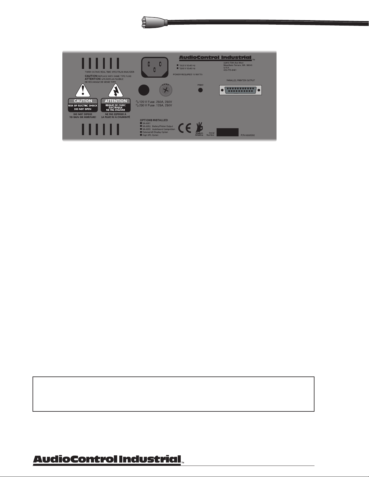
Connector Pin Designations
The printer interface connector uses a DB25F connector. The connector wiring is the same as that used by
PC-type computers so you can use any standard PC printer cable to connect the SA-3052 to your printer.
The connector pin designations are shown in Figure 3.2.
Figure 3.2. Parallel Interface Signals and Pin Assignments.
Battery Operation
A standard battery package allows the SA-3052 to be operated without connection to the AC mains supply.
ThebatterysupplyhassufcientcapacitytooperatetheSA-3052continuouslyfor3to4hours.Thebat-
tery package uses a sealed gel-cel, lead-acid battery pack.
An integral battery charger operates when the SA-3052 is plugged into the AC mains supply. The instru-
ment must be turned off to charge the battery.
Charging the Internal Battery Pack
1. Plug the SA-3052 into a suitable source of AC power.
2. Set the front panel powEr switch to off.
3. Leave the SA-3052 for a period of 8 to 10 hours (twice the discharge time).
4. The battery charger automatically adjusts the rate of charge as the battery reaches full charge. The
powEr/ChargELEDwillglowredthenashslowlywhenafullchargeisreached.Oncethisoccurs,
the battery charger switches to trickle-charge mode to maintain the battery at full charge. Operating the
SA-3052 on AC power will eventually discharge the battery.
Getting the Most From Your Battery Pack.
The SA-3052 uses a sealed, lead-acid storage battery. These batteries are not of the Nickel-Cadmium
typecommonlyusedforrechargeableapplications.Lead-acidbatteriesoffersomesignicantadvantages
over NiCad batteries.
• Given proper charging and discharge depth, the batteries should deliver 1000 to 2000 charge/dis-
charge cycles (4-5 years of normal operation).
• Lead-Acid cells do not have memory effects from partial discharging or charging.
• Higher energy density. The lead-acid design delivers more energy per unit volume than NiCad
battery systems.
• Lead-acid batteries can be charged in less time than NiCads.
• Wider temperature range: -65 degrees Celsius to +65 degrees Celsius.
3-4
Getting maximum performance from your battery pack is simple.
Follow these simple suggestions:
• Lead-acid batteries do not operate well when deeply discharged. Operate the SA- 3052 until the
green low-BattEryindicatorbeginsashing.Whentheindicatorbeginsashing,youhaveapproxi-
mately 30 minutes of operation left. Cease operation and recharge the battery or switch over to AC
power.
• A low-voltage cutout prevents operation of the SA-3052 once the battery voltage reaches this point.
The low-voltage cutout could make the instrument appear to be totally dead. If the SA-3052 appears
dead, plug the instrument into a source of AC power. Ensure that the powEr switch is set to the off
position. Leave the instrument plugged in for at least two hours and look for the red battery charg-
ing LED to glow continously.
If this "revives" the instrument, simply continue charging the batteries for another six to eight hours. If
not, consult the factory for additional information.
NOTE:
The low-voltage cutout could make the instrument appear to be totally dead. If the SA-3051/SA-3052
appears dead, plug it into a source of AC power. Ensure that the analyzer is turned off. Leave it
plugged in for at least two hours to charge. If the ChargE lED by the power switch does not light,
then you may not have AC power and the battery cells are not charging.
If this “revives” the SA-3051/SA-3052, you can resume normal operation using AC mains power. Be
sure to charge the batteries for another six to eight hours before using the portable battery mode.
Plugging the SA-3051/SA-3052 into AC mains while using the battery power may cause the micro-
processor to “hang”. If this occurs, turn the power off, then back on again.
CAUTION: Always store the SA-3052 with the batteries fully charged. Leaving the
analyzer stored with a partial charge for extended periods (more than two weeks) can
damage the battery cells irreparably. The battery charging circuitry cannot overcharge
the cells, so it is best to always leave the analyzer plugged into AC power for charging
whenever it is not in use.
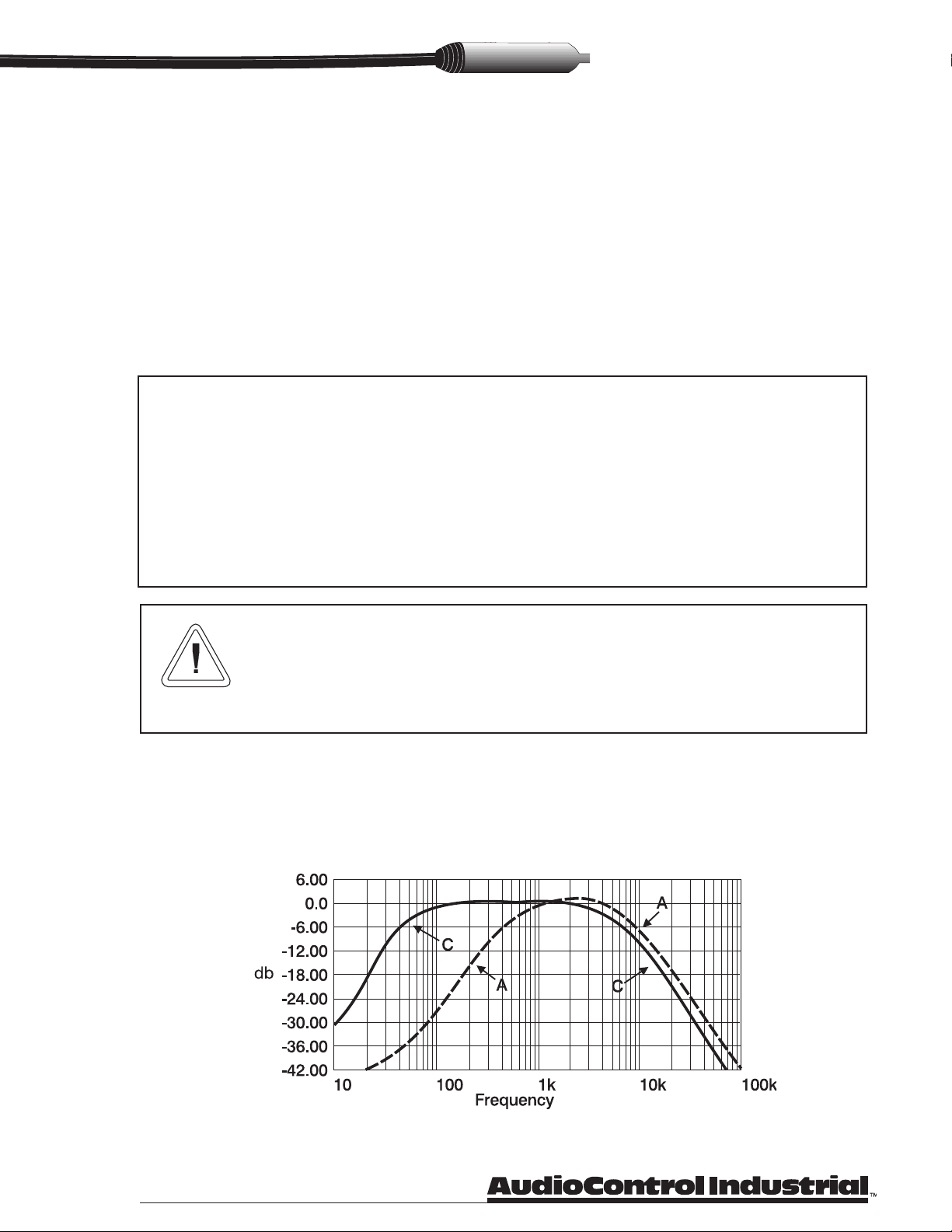
A and C Weighted Measurements
TheAC-10in-lineweightinglterprovidesA-orC-weightingtothemicrophoneinputoftheSA-3051/
SA-3052. Without the AC-10, the SA-3051/SA-3052’s measurements are unweighted. The AC-10 uses
activelterstocreatethetwoweightingcurves.Powerforthelterissuppliedbythephantompower
supply on the microphone input of the SA-3051/SA-3052.
Figure 3.3 A and C weighting lter response curves
Operation
3-5

SA-3051/SA-3052 Operation Manual
WARNING: Exposure to sound pressure levels in excess of 90 decibels causes hearing damage.
AudioControl Industrial assumes no liability or responsibility for hearing loss
incurred directly or indirectly by the use of the SA-3051/SA-3052. Please remember to
practice safe sound.
Lo Range Hi Range
70dB 110dB
80dB 120dB
90dB 130dB
100dB 140dB
110dB 150dB
120dB 160dB
Getting extreme at 175dB SPL
Input Sensitivity Scale Conversion
Figure 3.5 CM-10 microphone SPL-175 microphone
The standard SA-3051/SA-3052 measures sound pressure levels up to 136dB. The SPL-175 option
includes a high SPL microphone to allow measurements from 100 to SPL-175. The high SPL mode only
works in the digital SPL display mode. Don’t use the SPL-175 microphone for RTA measurements.
Selecting the SPL operating mode is very simple.
1. Press and hold the Spl button to enter the digital SPL mode.
2. The display will alternate HI and LO. Release the Spl button when the appropriate mode is displayed.
3. When the digital SPL mode is in the HI range, a single LED will stay lit at the left edge of the display.
Figure 3.6 SA-3051/SA-3052 display showing HI SPL mode Figure 3.7 HI SPL conversion scale
Hi Range
Indicator
To install the AC-10:
1. Unplug the CM-10 microphone from the mike cable.
2. Plug the AC-10 onto the end of the mike cable.
3. Plug the CM-10 into the AC-10.
4. Select the appropriate weighting curve with the a/C SliDE SwitCh on the AC-10.
3-6
gure 3.4 AC-10 weighting lter
This manual suits for next models
1
Table of contents
Other Audio Control Measuring Instrument manuals


