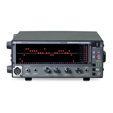
Audio Control R-130 User manual


Operating
Manual
R-130
One-Third Octave
"
Precision Real Time Spectrum Analyzer
making good stereo sound
better

This page intentionally left almost blank.
R-130 Operating Manual

TABLE
OF
CONTENTS
Introduction ..................................................................... 1
R-130 Highlights ...............................................................2
Filter Design......................................................................2
Display Options.................................................................3
Calibrated Microphone .....................................................3
Getting Started ..................................................................4
Quick Hook-Up Instructions ...........................................4
Features of the R-130 ......................................................6
Tour
of
the Front Panel .....................................................6
The Back Panel .................................................................9
Calibrated Microphone .....................................................9
Installation .....................................................
~
............... 10
Placement........................................................................ 10
Power Connections ......................................................... 10
Tips .................................................................................
11
Loop Placement .............................................................. 12
Preamp connection .........................................................
13
A
Primer
on Room Acoustics .......................................
13
Using the R-130 Spectrum Analyzer ........................... 16
Measuring with Pink Noise ............................................ 16
Sound system equalization ............................................. 19
Speaker Placement..........................................................20
Multi-amp balancing ......................................................
21
Component checking ......................................................
21
Looking at spectral response ..........................................
2.3
Limited
Warranty
.........................................................
24
Block Diagram ...............................................................
27
Specifications ..................................................................
28
R-130 Operating Manual

Introduction
R-130 Operating Manual
1
CONGRATULATIONS!
You now own one
of
the most useful and informative
frequency analysis devices ever available to the music
lover. The R-130's one-third octave configuration lets you
see -actually look at -sound more precisely than ever
before. Now you can see what you hear. The R-130 will
help you get more out
of
your speakers and your listening
room than you thought possible.
For
example, now you will be able to change the
speaker placement and not only hear the difference but see
which frequencies are affected and by how much. You will
be able to see how moving furniture in the room acts as a
mechanical, acoustical equalizer changing the sound, not
always for the better. With the R-130 you can meticulously
adjust a high quality one-third octave equalizer, like the
AudioControl C-131, to combat the mechanical equalizer
effects
of
room acoustics. And you can check the fre-
quency response
of
individual components such as tape
decks and compact disk players quite easily.
In brief, the R-130 can help you achieve extraordinary
sound quality and the sheer pleasure
of
high end musical
systems.
Clearly, these are strong promises.
We
believe they
can be made by AudioControl alone: The only consumer
electronics company in the world that specializes in equal-
izers and spectrum analyzers. And the company whose
professional sound division, AudioControl Industrial,
manufactures and sells the most popular real time spectrum
analyzer in the world, the SA-3050A.
Since 1978, AudioControl has been committed to this
specialized area
of
the audio world. Our passion for high
quality, meticulous attention to detail, and our professional
sound heritage shows itselfin the dozens
of
awards we
have won for our designs, products, service and quality.
However, our greatest satisfaction is our reputation for

sonic excellence and reliability with people like you
throughout the world.
Today you own a real time spectrum analyzer which is
the climax
of
all that we have learned from years
of
mak-
ing and selling spectrum analyzers in the no nonsense
world oftouring bands, recording studios, and presidential
press conferences, which is the world
of
pro sound. The
R-130 is hand crafted in very limited quantities by an elite
team ofAudioControl's most experienced and meticulous
personnel using the finest individual components. These
include special custom made filter capacitors, a fully
regulated power supply, blindingly fast operational ampli-
fiers, and a custom calibrated microphone.
What follows is a lengthy and occasionally
..rambling
discourse on what is the R-130, how to apply its fantastic
abilities, and some information on room acoustics. We
hope that you will read it thoroughly. Let the fun begin.
R-130
HIGHLIGHTS
Filter
Design
At the heart of any real time spectrum analyzer (and for
that matter any equalizer) is filters. The whole point ofa
spectrum analyzer is to show the user what is happening at
a specific bandwidth or frequency range. We want that
individual column
of
lights to show what is happening at
the specified frequencies and have the reading not be
affected by the bands on either side. You can think of
bandpass filters in the R-130 as windows or slots that only
let certain sound frequencies through and stop all the
others. Equalizers are very similar except the filters correct
the sound rather than drive a display.
At AudioControl, we spend our lives working on
making better filters since virtually every product we craft
includes at least half a dozen. The filters in the R-130 are
painstaking designed and manufactured using the latest
R-130
Highlights
-
Filter
Design
R-130 Operating Manual
2

Highlights -
Multiple Display
Options
Calibrated Microphone
Note: Only use
the supplied
AudioControl
microphone with the
R-130 analzyer
R-130 Operating Manual
3
computer techniques and custom capacitors made precisely
to
our specifications. It is a lot
of
work but,
as
you will see,
the results are worth it.
Multiple
Display Options
The R-130 can display on its LED screen a variety
of
different signal sources in a multitude
of
ways. It can
display music or test tones played through your stereo
system; both channels together or each channel individu-
ally. Or it can display what a microphone is picking up
including your dog's attempt
to
sing Jingle Bells. The
display can have a wide or narrow range, a fast or slow
speed, and be in a dot graph or a column bar mode. With
increasing experience, you will acquire the ability to SEE
the difference in speaker placement and other subtle musi-
cal cues. Even when you are not using the R-130 for these
important tasks, in the background it makes a fine light
show guaranteed to make the neighbors jealous.
Calibrated
Microphone
Included with the R-130 is an AudioControl calibrated
microphone with uncannily flat response like that
of
laboratory microphones costing many times more (believe
us we own a few and good computers cost far less). This
microphone has a funny shape on the business end to lessen
any diffraction problems and a long cord so you can easily
stretch it from your system to the favorite listening posi-
tion. To be honest, this microphone is a close cousin to the
famous CM-10 that is part
of
the AudioControl Industrial
professional (and more expensive) SA-3050A real time
spectrum analyzer. The microphone is a precision back
electret condenser microphone with a 1/4" element. Like
any precision instrument, handle the microphone with care
and use this mike, and only this mike, with the R-130.

IMPORTANT
INITIAL
STEPS
FILL OUT and mail the WARRANTY CARD that
came with your R-130. Also, save the sales slip
or
invoice
from the store where you bought your R-130. This is
extremely important for determining when your warranty
coverage began -and also for insurance purposes if(perish
the thought) someone appropriates your audio system some
dark night when you're vacationing in Tahiti, or
if
a stray
fireplace spark ignites your rare collection of Otto
Klemperer 8-tracks.
Also, save the packing box, plastic bag and foam
blocks which were used
to
pack the R-130. Should your
equalizer ever need service, it is important that the unit be
returned in the original packing.
"'
Getting
Started
Quick
Hook-Up
Instructions
QUICK
HOOK-UP
INFORMATION
FOR
THE
IMPATIENT
Since sometimes the best way
to
learn is just
to
get
started, we have provided fundamental hook-up informa-
tion first. This is a product with some basic functions but
also certain quite advanced capabilities. We urge you
to
make this manual bedside reading so you completely
understand all the wondrous things it can do.
The R-130 may be connected in two different spots and
by two different methods:
You can connect it
1)
in a Tape Monitor/External
Processor loop (the preferred method), or 2) between your
preamplifier and power amplifier (see figures 1 and 2).
If
you choose method
2,
be careful when injecting the pink
noise
as
you will need to turn down the level since you are
now putting a signal to the amplifier AFTER the volume
control.
You can use either conventional "RCA" -type inter-
connects or balanced XLR connectors in any combination. R-130 Operating Manual
4

Quick
Hook-Up
Instructions
Tape Deck
R-130
Reciever
Figure
1.
Tape loop connection
Pre Amp
R-130
Amplifier
Figure 2.
Preamp connection
R-130 Operating Manual
5
Balanced
Line
Inputs
L R
~~
•
0 •
0
Balanced
Line
Inputs
L R
~~
lelelelel
Tape
Out
In
•
0
r-lnputs-,
Main
Loop
•
0
In
Main
Out
In
•
0
rOutputs,
Main
Loop
Main
Out
lelelelel
rOutputs,
Main
Loop
•
0

After the R-130 connections are complete, you are
ready to start analysis (with apologizes to Mr. Freud). The
process is basically to use the pink noise generator in the
R-130 to play pink noise
out
of
your speakers and
put
the
calibrated microphone in your normal listening position.
Since the pink noise itself would show as a flat line, though
jittering somewhat due to its random character, any devia-
tion from this line is from the components and acoustics
between the pink noise source and the microphone.
We
suggest you read the later section for a more detailed
discussion
of
this process.
FEATURES
OFTHE
R-130
..
A
Tour
of
the
Front
Panel
-0
Q
0
,,,
..........
,.,,,,,..,,,.,,,.,
..............
,,,.,,,.,
..
,,,..,.,,,..,,.""""'""""'""""''""'
c=:J
I I
rc:::::::::J1
Mk
Sum
Uor•P>t
Lc:::JJ
c::=i
o,,pi.y
F
..
1•Slm•
'-
"~"""
~
o?
i:::::=J .
'------'
Features
of
the
R-130
Front
Panel
R·/30
On,,
ThitJOrta>~
R<alTi=Jpt<lt....,,t"<lly:er
The R-130 is designed so that once you have the signal Figure 3
controls connected
on
the rear
of
the unit all analysis and R-130 Front Panel
other test work may be carried out using the controls on the
front. Starting from the left here is an explanation
of
those
front controls.
Power.
The big round button must be pushed in to
tum
on the R-130.
If
some signal is present, you should imme-
diately see a display on the
LED
screen.
If
not check
connections and, as a last, resort check the fuse on the back
of
the unit.
Pink
Noise
Output
and
Level. There are two pink
noise outputs on the R-130. The one
on
the front
of
the unit
(a headphone type jack for 2 channel output) is always on.
R-130 Operating Manual
6

Features
of
the
R-130
Front
Panel
R-130 Operating Manual
7
The second output is fed pink noise when the button so
labeled on the lower left
of
the unit is pressed in. This
second output is the main output on the back and feeds
monophonic pink noise into your preamplifier
or
amplifier
for system and room analysis. Volume
of
the pink noise is
controlled for both these outputs by the conical knob also
on the lower left
of
the front panel. Always start any
procedure with the pink noise volume turned down.
Decibels
per
Step.
On
the left
of
the display window
are a column
of
control buttons, the top
of
which is the
decibels
or
dB per step control. Pressing this control
changes the real time display from 2 dB per LED to 4 dB
per LED. The 4 dB settings probably will be the one you
use most often
as
this shows the largest dynamic range on
the display. Use the 4 dB setting for program (music)
monitoring. The 2 dB setting gives a finer resolution for
precise measurements or equalizer settings.
Bar
and
Dot. The R-130 display can either be a dot
mode that looks like line graph with 30 dots
or
a full
column bar display. In the bar display mode, all the LEDs
under the highest one are illuminated and in this mode, the
R-130 may help light a darkened room.
Display
Speed.
If
you are using the R-130 to view
music the fast speed is the best as it shows you what your
ears hear. However for room analysis using pink noise, you
will find the slow speed more helpful since this speed
now
dampens the randomness
of
the pink noise.
Pink
Noise On/Off. The last button in the left column
we have already discussed above when explaining the pink
noise jack.
RTA
Display. The display window is a LED matrix
of
300 LEDs carefully selected for their brightness, shape,
speed, and shade. In each
of
the 30 one-third octave col-
umns there are 10 LEDs. This means at 4 dB per step the
range is a total
of
40 dB.

Channel Display Options. To the right
of
the display
window is a second column
of
control
buttons. The top two define what signal is
being displayed on the screen.
It
is pos-
sible
to
display both left and right chan-
nels together, the left channel alone, the
right channel alone, or the microphone
only. See the chart at right.
IN
Features
of
the
R-130
Front
Panel
"Right" Button
IN
OUT
Both
Channels
Summed
I
ILeft
I
channel
:Line Input
One nifty use for these controls is that
when doing a room analysis, you can
toggle between the test tone source on one
or both
of
the channels and the micro-
-----+-----
phone
to
see the difference.
Loop In/Out. Since the R-130 may be
occupying a precious tape or external
processor loop, this button controls the
addition of another such loop to replace
"Left"
Button
OUT
the one the R-130 uses. In other words, you can plug
something like an equalizer into the back of the R-130
as
shown in Figure
2.
Low/High Gain. Use the low gain setting
if
the R-130
is connected in the "loop" configuration and, m9st likely,
the high setting
if
the R-130 is between the preamplifier
and the amplifier. The high/low here refers to the signal
level ofthe input signal to the R-130.
Level. The conical level knob controls the display level
allowing you to center or adjust the display within the RTA
window.
Microphone Input. First, NEVER use any other
microphone than the official AudioControl R-130 cali-
brated microphone in this jack.
It
is possible that you will
damage another microphone by connecting it into this
receptacle.
1
I Mic
Right
Channel I Input
Line Input I
I
Figure4
Display Options
R-130 Operating Manual
8

Features
of
the
R-130
Back
Panel
Ba.lanced
lino
Inputs
' A
0 0
Figures
R-130 Rear Panel
R-130 Operating Manual
9
The
Back
Panel
of
the
R-130
WARNING:
SHOCK
HAZARD
-
DO
NOT
OPEN
1;:1
R-130 WARNING:
TO
PREVENT
FIRE
OR
rlnpw-----,
,-Outputs-,
ELECTRIC SHOCK HAZARD, DO
NOT
Qne-Th!trl
Octave
EXPOSE
THIS
PRODUCT
TO
RAIN
OR
""'"
""'
Aeal-Time
Am1lyrer
"""
""'
MOtsnJRE.
NO
USER SERVICABLE
PARTS
JNSIDE.
REFER
SERVICING
lO
0
oo, oo,
OUAUFIEO
PERSONNEL
ONLY.
D
CAUTION:
REPt.ACE
WllH
SAME
TYPE
Z50mA.
250V
FUSE.
AVIS:
RJSOUE
OE
CHOC
ELECTRIOUE
•
NEPASOUVfllR -
OOA
OOA
ATTENTION:
UTIUSER
UN
FUSIBLE
ll~#Tl!Slcw--
OE
RECHANGE
OE
MEM
TYPE
DE
0
~e:~=-
250mA,
250V.
•1toV..C!,aJ1;Gk:ZSlmA.
PmkNoisalsprusontonmD.0'1
Soria!-
W100VAC5'111<HU.'51lmA
outputswhenP!,..Nolsaswttch
Number
•Z'IIVACSQ.'SOIU
1l'5mA
,ow
....
on
rmnt
h;
p1ouod.
•NOV.0C:5C.'61JIU
IZ5mA
Looking at the rear panel ofthe R-130 and starting at
the left side are the balanced, XLR type inputs. Next to
these on the right are RCA jack inputs for both line inputs
and the "tape loop" inputs.
Similarly, the related outputs are farther to the right.
Pink noise is fed to the main outputs when that button is in
on the front panel.
If
you use balanced inputs, you can use
the RCA type main outputs without any problems.
The power outlet on the lower right is unswitched but
can effectively become switched
if
you plug the R-130 into
the switched outlet on another unit. Be careful
to
observe
and follow the maximum power rating on the switched
outlet though.
At the far right
of
the back panel, is the power cord and
the fuse holder.
If
it is necessary
to
replace the fuse, look
on the panel for the correct type and value and ONLY
replace the fuse with this one.
Calibrated
Microphone
The supplied microphone with the R-130 is a phantom
powered, precision back electret, condenser type. The
connection is unbalanced and the phantom powering is
supplied within the R-130. The microphone has a very flat
response and is painstakingly designed to give the very best
possible results with the R-130. Do not use any other
microphone with this unit other than the official

AudioControl microphone as they may be damaged and
most likely will not give proper readings.
The microphone comes with a non removable 20 foot
cord that should be sufficient for most circumstances.
If
you wish a longer cord, you can add another 1/4" type
microphone cord commonly available at music stores to
the male end. We do not recommend a total cord length
over 50 feet.
INSTALLATION;
THE
LONGVERSION
Placement
The R-130 has distinctive and attractive styling and
looks quite good with a stack
of
product. Being proud
parents like we are, we think it looks the best stacked with
a pair (or more)
of
its sibling, the C-131 one-third octave,
constant Q precision equalizer. However you stack it, make
sure not to block the ventilation slots on any components
and avoid placing the R-130 directly over a beefy power
amplifier that gets hot, particularly
if
you have one
of
those
tube amplifiers that some people use to heat their house.
Power
Connection
The R-130 draws only eighteen watts and thereby can be
connected to the switched AC outlet
of
any preamplifier or
receiver. By the same token, its low power draw means
that you can actually leave it on continuously
if
you have'
other equipment that is also left on.
Installation
Placement,
Power
Connection
R-130 Operating Manual
10

Installation
General
Connection
Tips
R-130 Operating Manual
11
General
Connection
Tips
Although we assume a general level
of
sophistication in
any owner who has acquired an instrument such
as
the
R-130 one-third octave real time spectrum analyzer, the
following tips can never be repeated too many times.
~
Tum
off all components before making any connec-
tions.
~
If
using the R-130's conventional "RCA" input/output
sockets, make sure that "left is hooked
to
left and right is
hooked to right" at each connection. The obvious and
time honored way
to
assure this is to assign one hook-up
cord plug color to left and the other
to
right. Generally,
Red signifies Right and White, Grey or Black then repre-
sents left.
~
Whenever possible, keep power cords away from signal
cables (inputs from CD player, tape deck, etc.) to prevent
hum (which is not a problem with balanced connections).
This is especially important for turntable cables that carry
very weak signals. While hum is less ofproblem today
than it was in the past, noise can still find its way into your
system
if
a component's power cord becomes too inti-
mately wrapped up with a hook-up cable. The R-130's
power cord is on the right side
of
the chassis (when viewed
from the posterior). This allows you to bundle all the
power cords and keep them separate from signal connec-
tions.
~
Types
of
interconnects There are many different
grades
of
hook-up cables. Some cost
as
much
as
$100 per
meter (we hear rumors of some costing more). Whether or
not you use "audiophile" interconnects is your choice and
depends upon your preference, your ability
to
discern

minute differences and whether you have the R-130
hooked up in a dead end or through type connection.
However, avoid really CHEAP connection cables
as
they
can sometimes disconnect themselves internally causing a
loss of signal or hum problems. So, before you send the
R-130, or any other components for that matter, in for
service, swap hook-up cables to see
if
they are the culprit.
R-130
Preamp
Loop Installation
Installation
-
Loop
Installation
If
your preamplifier has an unused tape monitor loop or de.dicated external processor loop,
the R-130 may be connected as shown above. Connecting the R-130 in this type
of
loop
is the PREFERRED method
of
connection.
If
you own the marvelous C-131 one-third octave, constant Qprecision equalizer, you can
easily connect the R-130 by using the special output
of
the C-131.
R-130 Operating Manual
12

Installation -
Preamp
Connection
Straightwire
R-130
A goodly number
of
less-is-more preamplifiers intentionally omit tape loops (or include
just one). Also,
if
you are connecting a CD player with variable outputs directly
to
your
power amplifier, this also indicates how
to
place the R-130 in that sort
of
simplified
signal chain.
If
you choose this connection method, BE CAREFUL when injecting pink
noise into the system. TURN DOWN the pink noise volume on the front
of
the R-130 as
the R-130 is
AFfER
your preamplifier's volume control and you may be in for a nasty
surprise otherwise.
R-130 Operating Manual
13
A
Primer
on
Room
Acoustics
Magazine reviewers and owners spend much time
critically appraising speakers and other stereo components.
Unfortunately, a very large effect upon sound is not so
easily judged or changed and that is the acoustics
of
the
environment in which you are listening. Room acoustics is
a complicated subject. What we want to do here is point
out a few basics and refer you to other sources
if
you want
more detailed information.
Sound is waves, as you probably learned in junior high
school. Waves like those on a pond hit each other and get
bigger (reinforce) or smaller (cancel). Since sound is
energy, the way it reflects depends upon the angle
of
the
surface and the type
of
reflecting material and the fre-
quency
of
the wave (among other things, but this is getting
complicated enough this fast). Because some sound has
more energy than others and may reflect better, some

sounds last longer in a room. Also, some
sounds are a more important concern
because they create standing waves at
certain frequencies i.e. that is a reflection
pattern than causes a stationary pattern
of
sound pressure levels.
Different frequencies
of
sound have
different wave lengths and create acousti-
cal effects in different ways. The wave-
length is a function
of
the frequency and
the speed
of
sound. The table here gives
you the equation for sound in air (the
speed is different in other things, like
water for example) and wave lengths at a
number
of
frequencies. As you can see,
wave lengths go from under an inch (2
centimeters) to over 50 feet (15 meters)!
Room
Acoustics
rd
walls--------
lllilil,i
~
SPLmaxima
Figure 6 -
Standing waves between two
parallel
swfaces
Figure 7 -
Soundfields
R-130 Operating Manual
14
..

Wave
Lengths
of
Sound
in
Air
References
1.
The Master Handbook
of
Acoustics, F. Alton Everest, Tab
Books
2.
Handbook
for
Sound
Engineers, Glen Ballou, SAMS
3. Sound System Engineering,
Don and Carolyn Davis, SAMS
4. Acoustics, Leo Beranek, Old
Colony
R-130 Operating Manual
15
Wave
Lengths
of
Sound
in
Air
Vyave
length _ 1120 feet er second
(m feet) -requency eye es per second)
Speed
of
Sound in Air =1120 fps
Frequency Wave length
in Hertz in feet
20 56
25
44.8
30 37.3
40
28
50 22.4
80 14
120 9.3
200 5.6
300 3.7
500 2.2
1000
1.1
2000 0.6
4000 0.3
8000 0.14
16000 0.07
20000 0.056
All
of
this is greatly complicated by the fact that few
listening rooms are perfectly rectangular, which means
predicting sound interaction patterns is very difficult due to
the irregularities
of
the room shape.
If
this
isn't
enough,
sound reflects differently offcertain surfaces (glass and
sheetrock for example) at high versus low frequencies.
As you can see, room acoustics is an important but
involved subject. In effect, the room becomes a mechani-
cal equalizer boosting or cutting certain sounds. The R-130
will let you see the effects
of
changes and do something

about them. To learn more about room acoustics, please
read AudioControl technical paper number 107 enclosed
with this unit on small room acoustics.
Additional references for your further study are listed
below. One caution though, much of the information
published on room acoustics is for large rooms, i.e. concert
halls, recording studios. Be sure when you are reading this
information, it is also applicable for small listening rooms.
R-130
APPLICATIONS
AND
TECHNIQUES
Room
Measuring
Using
Pink
Noise
Briefly, the procedure is to take a known test sound,
play it through the system, pick up the resultant sound with
a test type microphone, measure the signal, and display the
frequency response on the real time spectrum analyzer. The
differences between the test signal and the display are the
modifications made by the room and/or stereo equipment.
In more detail, here is the procedure with further explana-
tion
of
some ofthe terms at the end.
FlatTest Sound
(Pink Noise)
Listening
Environment
Actual Response
of
Room & Speaker
Applications and
Techniques
Measuring Pink
Noise
Figure 8 -
Audio Analysis
R-130 Operating Manual
16
Table of contents
Other Audio Control Measuring Instrument manuals
