Leader Search User manual


1
Product references
D11.04.330
LEADER Search 2 wired sensors.
D11.04.331
LEADER Search 3 wired sensors.
D11.04.332
LEADER Search 2 wireless sensors.
D11.04.333
LEADER Search 3 wireless sensors.
D11.04.334
LEADER Search 6 sensors (3 wired + 3 wireless).
D11.04.361
LEADER Search 2 wired sensors (version basic pack piles).
D11.04.364
LEADER Search 2 wireless sensors (version basic pack piles).
D11.04.365
LEADER Search 4 sensors (2 wired + 2 wireless) with probe COM

2
1INTRODUCTION ----------------------------------------------------------------------------------------------------------------------------------------------- 3
1.1 LEADER SEARCH PRESENTATION ------------------------------------------------------------------------------------------------------------------------ 3
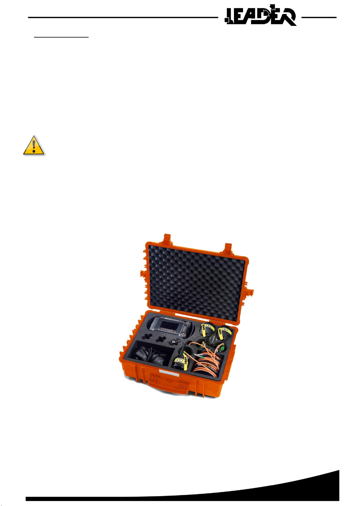
1.2 LEADER SEARCH COMPOSITION ------------------------------------------------------------------------------------------------------------------------- 3
1.3 GENERAL FUNCTIONS ------------------------------------------------------------------------------------------------------------------------------------- 5
1.4 DETAILED TECHNICAL SPECIFICATIONS-------------------------------------------------------------------------------------------------------------------- 5
2LEADER SEARCH DESCRIPTION --------------------------------------------------------------------------------------------------------------------------- 6
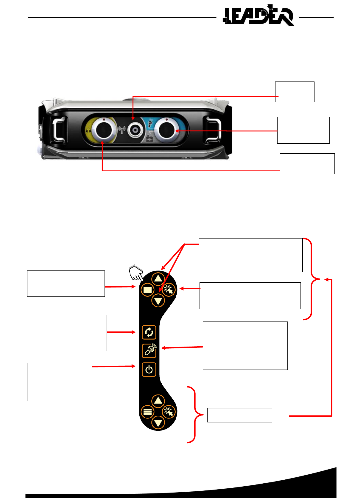
2.1 CONTROL BOX DESCRIPTION ------------------------------------------------------------------------------------------------------------------------------ 6
2.2 CONNECTION DESCRIPTION ------------------------------------------------------------------------------------------------------------------------------- 7
2.3 KEYBOARD DESCRIPTION ---------------------------------------------------------------------------------------------------------------------------------- 7
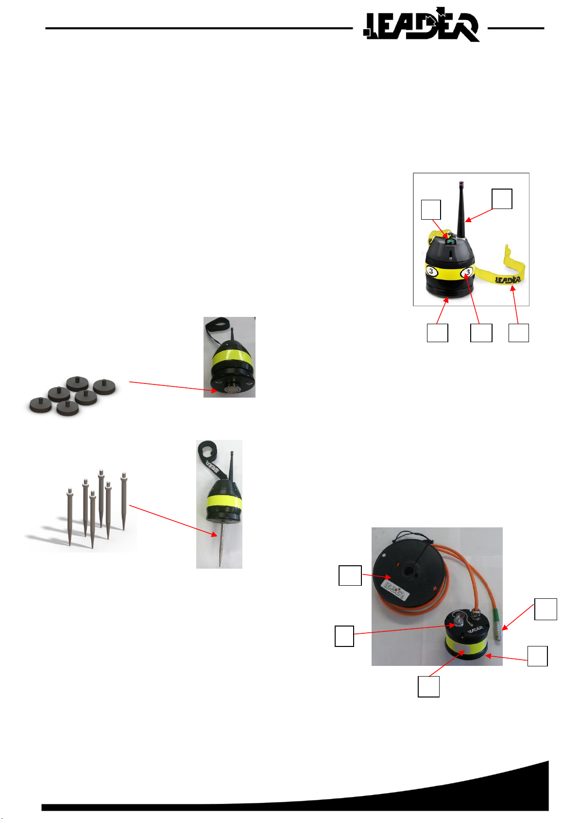
2.4 DESCRIPTION OF THE WIRELESS SEISMIC SENSOR -------------------------------------------------------------------------------------------------------- 9
2.5 DESCRIPTION OF THE AUDIO PROBE -------------------------------------------------------------------------------------------------------------------- 10
2.6 DESCRIPTION OF THE HEADSET ------------------------------------------------------------------------------------------------------------------------- 10
3USING THE CONTROL BOX------------------------------------------------------------------------------------------------------------------------------- 11
3.1 CONTROL BOX POWER SUPPLY-------------------------------------------------------------------------------------------------------------------------- 11
3.2 POWERING ON THE CONTROL BOX --------------------------------------------------------------------------------------------------------------------- 12
3.3 USING THE SUN SHIELD---------------------------------------------------------------------------------------------------------------------------------- 13
4SEISMIC SEARCH MODE ---------------------------------------------------------------------------------------------------------------------------------- 14
4.1 USING THE SEISMIC SENSOR ---------------------------------------------------------------------------------------------------------------------------- 14
4.2 PAIRING THE SEISMIC SENSOR -------------------------------------------------------------------------------------------------------------------------- 15
4.3 MENU:DESCRIPTION OF THE SEISMIC MODE FUNCTIONS -------------------------------------------------------------------------------------------- 16
4.3.1 Seismic mode ------------------------------------------------------------------------------------------------------------------------------------- 16
4.3.2 FONCTIONS SELECTION ------------------------------------------------------------------------------------------------------------------------ 17
4.3.3 Filter control function -------------------------------------------------------------------------------------------------------------------------- 18
4.3.4 Sensor battery level function----------------------------------------------------------------------------------------------------------------- 18
4.3.5 Function to set screen brightness ----------------------------------------------------------------------------------------------------------- 20
4.3.6 Audio probe function --------------------------------------------------------------------------------------------------------------------------- 21
5TROUBLESHOOTING --------------------------------------------------------------------------------------------------------------------------------------- 22
6WARRANTY -------------------------------------------------------------------------------------------------------------------------------------------------- 23

3
1 INTRODUCTION
1.1 LEADER Search presentation
The LEADER Search is designed for use in rescue operations and uses seismic technology to find
signs of life. It is used to detect the presence of victims buried under rubble and pinpoint their exact
location.
This exceptionally sensitive device is likely to detect the slightest sounds made by victims.
The LEADER Search is fitted with ultra-sensitive wireless and wired seismic detector sensors and
an audio probe (only in its full 6 sensors version otherwise it is an option). It adapts to the type of use
without any adjustments. It is available in a 2 wireless sensor version, a 3 wireless sensor version,
a 2 wired sensor version, a 3 wired sensor version and a 3 wireless plus 3 wired sensor version.
This equipment is fitted with adjustable filters that are used to reduce parasite noise such
as pneumatic drills, the passage of trucks, etc.
1.2 LEADER Search composition
1 watertight and shock proof transport case.
1 control box with screen and keyboard with its straps (shoulder strap and hand strap).
1 stereo anti-noise headset with microphone.
1 waterproof audio probe for communication with the victim, depending on version.
2 to 6 wireless, high sensitivity seismic sensors, depending on version.
3 to 9 AAA batteries to power the wireless seismic sensors, depending on version.
2 to 6 magnetic plates (magnets) for the use of the sensors on metal structures.
2 to 6 probes for use of the sensors on loose soil.
1 removable antenna to be fitted on the control box to enable wireless communications between
the sensors and the control box.
1 rechargeable control box battery pack.
1 100/240V 50/60Hz charger block.
1 set of international adapters.
1 backup battery pack for 10 AAA batteries (not included).
1 sun shield.
➢Different release:
Wire sensor
Wireless Sensor
Probe for COM
D11.04.330
X2
-
-
D11.04.331
X3
-
-
D11.04.332
-
X2
-
D11.04.333
-
X3
-
D11.04.334
X3
X3
X1
D11.04.361
X2
-
-
D11.04.364
-
X2
-
D11.04.365
X2
X2
X1

4
Available options:
•1 seismic wire sensor fitted with 8 m or 26 ft of cable and a reel.(Réf: D11.04.336)
•1 seismic wireless sensor (range: over 100 m or 330 ft in open field). (Réf: D11.04.335)
•1 Magnetic plates (magnets). (Réf: 2003514)
•1 Spikes for use of the sensors on loose soil. (Réf: 2003113)
•1 stereo anti-noise headset with adapted microphone and connectors.(Réf: D11.04.340)
•1 waterproof audio probe for communication with the victim. (Réf: D11.04.347)
•Extension for the audio sensor cable up to 100 metres or 330 ft on a reel.
•Extra battery pack. (Réf: D11.04.341)
• Read the instructions carefully before using the product.
• The device should not be dropped or suffer shocks.
• Do not disassemble the product as this will invalid the warranty.
Do not attempt to repair the product or replace parts (except when this manual
provides specific instructions to do so). Refer all servicing to your distributor,
or at LEADER maintenance service.

5
1.3 General functions
FUNCTIONS
IN SEIMSIC SEARCH
MODE
Audio headset volume control
Yes
Microphone volume control
Yes
Push to Talk
Yes
Screen brightness control
Yes
Noise filter control (low and high pitch)
Yes
Wireless sensor charge level indication
Yes
Battery charge level indication
Yes
Separate control of each seismic sensor
Yes
Mono or Stereo listening mode (listen to selected
sensors using 1 or both ears)
Yes
Visualisation markers to identify the strongest seismic
peak
Yes
1.4 Detailed technical specifications
Refer to product data sheet available on our website at www.leader-group.eu.

6
2 LEADER Search DESCRIPTION
2.1 Control box description
The polypropylene control box is composed of:
•A 5 inch TFT colour 16/9 high brightness screen.
•A keyboard for settings and scrolling through the different menus.
•A rechargeable battery pack.
•A removable aerial to communicate with the wireless seismic sensor(s).
•Connectors for the watertight connection of the Sensor and Probe COM, antenna and audio headset.
Colour coding to assist in the rapid connection of each element to its corresponding connectors.
•A waterproof cap to fit to the aerial connector when not used.
•A rubber band around the edge for better shock protection.
•4 attachments to fix the carrying strap and the handle.
The control box:
•Has an ergonomic graphic interface including an intuitive menu with subtitles in English only.
•Is reversible for use by a right handed or left handed operator (function selectable from the menu).
•Is IP54, i.e. water and dust resistant.
•Has been tested to be resistant to 2 metre falls.
•Offers the possibility of using a second optional headset at the same time as the first, for use by
an interpreter, a doctor or an instructor.
•Is supplied with a sun shield.
•To clean, use a dry and soft cloth.
•Never use solvents, or alcohols of any kind, to avoid of discoloration
and / or distortion of the unit.
•Avoid blows or excessive pressure on the screen.

7
2.2 Connection description
For easier connection of the accessories:
•Each female connector on the control box is identified using a colour code and a symbol.
•Similarly, the cable for each accessory has a coloured ring around the male connector corresponding
to the colour code on the control box connectors.
2.3 Keyboard description
The keyboard has photo luminescent keys for better visibility in the dark.
Audio headset
connector
Aerial
connector
Wire Sensor or
Probe COM
connector
Up / Down keys: Used to scroll
through the menu and position
settings such as the sound level.
Validation/Selection key:
Used to select the required function
and to validate a setting.
"Toggle" key: Used to
change listening modes
(MONO or STEREO).
ON/OFF Key: Used to
power on the control
box by pressing it 2
seconds.
Push-to-Talk key: Using the
audio sensor function
keeping this key pressed
down makes it possible for
the rescuer and the victim to
communicate.
Duplicate keyboard.
Menu key: Used to display
settings menus and user
menus.

8
Used to refine
the listening mode
for wireless sensors.
Used to refine
the listening mode
for wired sensors.
Headset
Wireless Sensor
Control Box
Probe COM
Wire Sensor

9
2.4 Description of the wireless seismic sensor
The LEADER Search has the wireless seismic sensors which are used to locate a buried victim.
These exceptionally sensitive sensors are capable of detecting the slightest sounds made by victims.
The different search methods are not explained in this manual. Refer to the operational search
instructions used in your field interventions.
In an open area these wireless sensors have a maximum range of 100 m.
In operation, depending on the configuration of the zone, these wireless sensors can be used up to about
30 m.
A wireless sensor has:
•A/ a removable base to access the battery compartment
(3 AAA batteries).
•B/ an aerial.
•C/ an ON/OFF button with LED.
•D/ a strap to handle the sensor in the ruins or rubble.
•E/ a number corresponding to its pairing number.
Magnetic plates (magnets)
Each wireless sensor is shipped with a magnetic
plate that can be screwed directly onto its lower
part. This plate can be used on the metal beams
of collapsed buildings which are well known
to conduct vibrations optimally.
Metal probes Each sensor is also shipped with a probe
that can be screwed directly onto its lower part.
These probes are used on loose soil to increase
vibration reception.
A wire sensor has:
•A/ wire sensor.
•B/ cable reel with 8m.
•C/ connector to box or 2nd sensor.
•D/ connector for 2nd sensor.
•E/ sensor corresponding number.
The first sensor is wired to connect on the box, the second is to connect the first sensor.
A
C
D
E
B
A
C
B
D
M
E

10
2.5 Description of the audio probe
The audio sensor can be used both to communicate with and
listen to a victim. Its 8 metre or 26 ft cable makes it possible
to communicate with the victim in most cases. It is water
resistant (IP 67) and its 38 mm or 1.5 in diameter makes
it possible to use it in core sample drill holes. The sensitivity
of the microphone makes it possible to hear whispers.
2.6 Description of the headset
The audio headset is used to:
•Communicate with the victim.
•To listen to the wireless sensors.
A second optional headset can be connected to the control box using a Y connector allowing two headsets
to be connected to the same connector.
Microphone
Speaker

11
3 USING THE CONTROL BOX
3.1 Control box power supply
The LEADER Search is delivered with a lithium polymer battery pack which is inserted into the back
of the control box.
The battery pack is recharged SEPARATELY from the control box.
Charging can be carried out at between 0°C and 45°C (maximum temperature) using the supplied
charger.
During charging, a LED located on the charger provides the following indications:
▪Green: battery charged or battery not connected to the charger.
▪Red: battery charging.
During operations, if the battery pack is run down, the user can either use another battery pack
(supplied as an option), or the backup battery pack as a replacement for the initial battery pack.
The backup battery pack requires 10 AAA batteries (not provided).
The battery pack can ONLY be charged using the supplied charger block. It can be used with
100/240VAC - 50/60Hz
The international adapters can be used to recharge the battery pack on all US, Australian, European,
and UK power outlets.
Once the appliance is powered on, if the camera or at least one seismic sensor is turned on, an icon showing
the battery pack charge level remains displayed on the top right of the screen.
5 icons to show the control box battery
pack charge level.
Icon displayed when the
backup battery pack is being.
used
Mains adapters
Charger block
Battery pack

12
3.2 Powering on the control box
Powering on
The device is powered on by pressing the ON/OFF key once.
On powering on, a first screen is displayed.
A loading screen quickly follows. On the bottom left of the screen it shows the version of the device software
and on the bottom right the serial number.
If neither the probe nor the sensors areconnected, the screen shows the following icons "sensor not connected".
The device will remain on this screen for 5 minutes before powering off automatically if no action is detected.
Turning off the control box
To turn off the control box, press the ON/OFF key for 2 seconds.
LEADER Search version 1.0.3

13
3.3 Using the sun shield
In bright light, the sun shield is used to place the screen in a dark area
to be able to see it better.
To hold the sun shield on the control box it must be correctly positioned
on the face on the forms designed to this effect. The red line shows
the position.
The wide elastics are used to ft it quickly and easily.
It is stored flat for easier transport. An elastic on its side is used to keep it flat and fix
it to the control box. By placing it on the screen face, it protects the screen when moving around
when the search device is not in use.

14
4 SEISMIC SEARCH MODE
4.1 Using the seismic sensor
To power on the wireless sensor, the push button must be pressed for at least 1 second. When the sensor
is powered on, the green push button LED lights:
•Slow flashing: no connection with the control box.
•Fixed: connection with the control box in progress.
•Fast flashing: connection with the control box
established.
•Very fast flashing: pairing sequence in progress (see
Pairing section).
To power off the sensor, the push button must be pressed for at least 1 second.
If the sensor does not connect with the control box, it powers off automatically
after 20 seconds.
To connect several wireless sensors, it is important to use the following powering
on sequence:
1. Power on the control box until the LEADER Search logo is displayed.
2. Press the sensor push button. When its LED flashes quickly the connection is complete
and the corresponding sensor bar chart appears on the control box screen.
3. Repeat step 2 for the next sensor.
Important: Do not power on all the sensors at the same time, but one after the other.
Wait for the powered on sensor to appear on the screen before powering on the next sensor.

15
4.2 Pairing the seismic sensor
To be recognised by a control box, the sensors must be paired to it. Initially the sensors are paired with
the control box they are delivered with in the factory.
However, each sensor can be used on any LEADER Search control box.
If you need to pair a sensor to another control box, follow the sequence described below:
1. Turn off the control box.
2. With the sensor powered off, press the push button for 15 seconds and then release it. The green
LED will flash very quickly and then go out at this stage the sensor is no longer paired to any control
box.
3. Turn on the sensor to be paired. The sensor's LED flashes very quickly again. If the LED
on the sensor to be paired does not flash quickly, repeat step 2.
4. Turn on the control box. The sensor will then carry out the pairing sequence for a few seconds
and then switch off automatically.
5. Switch the sensor back on. it is now recognised by the control box and its bar-chart format signal
appears on the screen.
A selector in the sensor battery compartment can be used to select the sensor number (n°1, n°2 or n°3).
The sensor number is memorised by the sensor during the pairing sequence. To make the sensor memorise
a new number, it should first be unpaired, the switch must be placed on the required sensor number,
and then the pairing sequence carried out.
Once paired, the sensor keeps the number assigned to it, even if the selector is mistakenly positioned
on another number.

16
4.3 Menu: Description of the Seismic mode functions
4.3.1 Seismic mode
The seismic menu appears when one or more seismic sensors are connected. The bar-charts are shown
for each connected sensor, with the maximum level carried over. By default the sensor sound gain is set
to 50%. The browser "▲" keys increase the gain for all sensors and the "▼" keys reduce it.
A headset icon placed under each bar graph indicates that the sensor is audible. It is MONO:
the sound can be heard in both ears.
The option to listen or not listen to a sensor is made using the keyboard keys located below each bar
chart. In the configuration below each sensor can be heard in both earphones on the headset.
There is a second listening mode
on the seismic menu: STEREO mode.
It is used to concentrate listening
to the sensors using the left or right ear.
This second mode can be accessed by
pressing the "Toggle" key. Once this
mode has been selected, the user can
listen to each sensor in the left or right
headset earpiece using the keyboard
keys located beneath each sensor
(or all the sensors at the same time).
This listening direction is shown by
an arrow pointing left when listening
in the left earpiece, and pointing right
for the right earpiece.
The tracer turns red on the sensor that detects the highest peak. If 2 sensors
detect the highest peak at the same time, then they will both be red. This tracer
is carried over onto the scale for easier readings.
Sensor numbering
Force scale
Yellow tracer showing
the sensor's maximum
response
MONO mode audible sensor indication (sound in both ears)
Selection keys to refine
the sensor listening
mode settings
Sensor response
Sensor gain
Battery level indicator
Sensor being listened
to in the left earpiece
Sensor being listened
to in the right earpiece
Sensor not being listened to

17
4.3.2 FONCTIONS SELECTION
The menu button is used to access the different menus.
Up to five icons can then appear.The "▲" and "▼" browser keys are used to select the required
menu. Once the menu has been selected, pressing the validation key gives access to the menu.
Pressing the menu key again is used to exit the menu and return to the main screen.
The "filter high" function gives access to low-pass filter settings
and is used to remove sharp noises. Its cut-off power is used to remove
all frequencies above its setting threshold (Setting threshold: 600Hz
to 3000Hz).
The "filter low" function gives access to high-pass filter settings
and is used to remove bass noises. Its cut-off power is used to remove
all frequencies below its setting threshold (Setting threshold:
20 Hz to 300Hz).
The "com probe" function gives access to audio sensor use
and its settings. The icon is only displayed if the audio sensor
is connected to the LEADER SEARCH.
The "battery levels" icon gives access to the battery levels
on the connected wireless sensors. The icon is only displayed if at least
one wireless sensor is connected to the LEADER SEARCH.
The "brightness" function is used to set screen brightness.

18
4.3.3 Filter control function
The LEADER Search is equipped with two filters that are used to remove surrounding noise,
a"low-filter" and a "high-filter". The seismic sensors can detect vibrations from 20 to 3000Hz.
The filters are used to remove parasite noise that is inevitable during an intervention or caused by the weather.
By default the filters are not activated. The settings bar at the right of the screen is at the minimum.
The "▲" and "▼" navigation keys are used to increase or reduce the selected filter's cut-off frequency.
Filter use:
To eliminate parasite noise, increase the low filter cut-off frequency until the noise disappears from
the headset. If the noise can still be heard, reset the low filter to zero and repeat the operation using
the high filter. To exit filter settings, press the menu key.
4.3.4 Sensor battery level function
Once selected, the "battery level" battery function is used to view the “battery level”for each connected
wireless sensor. A six level scale clearly shows sensor autonomy. To exit the battery menu, press the menu
key.
Wireless sensor autonomy is about 8 hours and varies depending on the type of batteries used
(3 AAA batteries). The screen below shows 3 connected sensors.

19
Wireless connectivity
Wireless devices are subject to environmental constraints which affect their use.
A wireless desk telephone, for example, can have connection/reception difficulties. However it is not less
useful than a wired telephone!
Indeed, in some cases linked to the location itself, interferences can prevent the signal from being displayed
on searching device for a few seconds. It returns in a reasonable period to continue searching.
To make it right; Adopt the attitude of someone who is aware that the wireless equipment has certain usage
constraints and apply the following advice to your victim search equipment:
- Place the sensors in view of the control box: Avoid placing them in holes.
- Position yourself up high with the control box.
- Leave as much free space as possible between the control box and the sensors: Nobody between the box
and sensors; the human body creates a natural barrier; do not show your back to the sensors.
- Consider the weather: depending on humidity/electricity in the air/sun, wireless will work better or worse (eg:
A radio can emit further in good weather).
Despite these constraints, wireless technology unquestionably has operational advantages which overcome
them:
- Rapidity of movements in rubble (no trapped wires).
- Safety of sensor holder during moves (no imbalance due to trapped wire).
- Efficiency of the search operations (larger zone covered).
- Freedom of movement.
- 30m range on average, much broader than the length of wired sensors (8m in general).
Low battery display
A battery icon displays above the corresponding graph bar when the batteries of a sensor become low
(20% remaining power).
With a low battery level, it increases the risk of disconnections and reconnections. It is therefore recommended
that you replace the batteries with new ones.
Here, the 3 sensor batteries are low.
It is also possible to view the battery charge level by selecting “sensor battery” in the menu.
Table of contents
Other Leader Measuring Instrument manuals

Leader
Leader LV 5480 Parts list manual

Leader
Leader LT 4446 User manual

Leader
Leader LV 7770 User manual

Leader
Leader LV5300 Installation guide

Leader
Leader LV 7770 User manual

Leader
Leader PHABRIX Rx 2000 User manual

Leader
Leader LE 8682 User manual

Leader
Leader LV 7380 User manual

Leader
Leader LV 7800 User manual

Leader
Leader LV5300A User manual