Audio international CL12/16W Series User manual

7300 Industry Drive, North Little Rock, AR 72117
Phone: 501-955-2929 Fax: 501-955-2988
www.audiointl.com
Installation & Operation Manual
Model #: CL12/16W Series
12/16 Watt Cabin Light Assembly
Document #540037

Audio International, Inc. CL12/16 Watt Series Cabin Light
Installation & Operations
Document #540037, Rev. B, 4/2000 Page 2 of 11
Document Revision History
Rev. Level Date Description
IR 3/1998 Initial Release
A 2/1999 ECN#3242, Include –33, -53, -63 configurations
B 4/2000 ECN#4618, Include –71, -73 configurations
Reference Documents
Document # Drawing # Description
N/A 520368 Outline Drawing, Cabin Light, 12/16 Watt w/internal fan
Service Bulletin List
Service
Bulletin # Subject Manual
Revision Revision
Date
Table of Illustrations
Illustration # Description Page #
1 Reference Drawings 11
PROPRIETARY NOTICE: Despite any other copyright notice, this document and information disclosed herein contains confidential,
proprietary designs owned by Audio International, Inc. Neither this document nor the data contained herein shall be reproduced,
used or disclosed to anyone without the written authorization of Audio International, Inc.

Audio International, Inc. CL12/16 Watt Series Cabin Light
Installation & Operations
Document #540037, Rev. B, 4/2000 Page 3 of 11
Table of Contents
Section Description Page
1.0 General Information ……………………………………………. 4
1.1 Introduction ……………………………………………………….. 4
1.2 Purpose of the Equipment ………………………………………. 4
1.3 Operational Features …………………………………………….. 5
1.4 Optional Equipment ……………………………………………… 5
2.0 Application ……………………………………………………….. 5
2.1 Introduction ……………………………………………………….. 5
3.0 Installation ……………………………………………………….. 6
3.1 Prior to Installation ……………………………………………….. 6
3.2 Unpacking and Inspection ………………………………………. 6
3.3 Cautions & Warnings …………………………………………….. 7
3.4 Wiring Requirements …………………………………………….. 7
3.5 Physical Characteristics………………………………………….. 7
3.6 Electrical Characteristics…………………………………………. 8
3.7 Mating Connector Information ……………..……………………. 8
3.8 Pinout Assignment Descriptions ………………………………... 8
3.9 Post-Installation Test …………………………………………….. 9
4.0 Operations………………………………………………………… 9
5.0 Troubleshooting Guide………………………………………… 10
5.1 General Troubleshooting Procedures ………………………….. 10
5.2 Troubleshooting ………………………………………………….. 10
6.0 Specifications …………………………………………………… 10
7.0 Reference Drawings ……………………………………………. 11

Audio International, Inc. CL12/16 Watt Series Cabin Light
Installation & Operations
Document #540037, Rev. B, 4/2000 Page 4 of 11
MODEL # CL 12/16 W Series
Cabin Light Assembly w/Internal Fan
1.0 General Information
1.1 Introduction
This manual contains information for the proper installation and operation
of the Audio International, Inc. (AI) 12/16 Watt Cabin Light Assembly with
Internal Fan. Also included are physical and electrical characteristics of
the unit.
1.2 Purpose of the Equipment
The CL12/16Wxx-xx series cabin lights are halogen reading lights that
contain an internal fan for cooling purposes. The brilliant halogen bulb
delivers maximum color-correct illumination with the beam specially
focused for even light intensity and comfortable viewing. The light
assemblies are built to rugged aircraft standards and are easily
incorporated into new or existing lighting systems.
Refer to section 3.8 for specific model numbers and their descriptions.
1.3 Operational Features
Listed below are key features of the CL 12/16 Watt Series Cabin Lights:
q
Self-contained bright/dim electronics
q
Do not require separate modules or controls
q
Simple on/off or on/off with dimming (single or dual button control)
q
Available in square or round mount
q
Raised trim ring for easy grip positioning
q
Internal cooling fan
q
Forty-two degree swivel range provides approximately 1.5’circle of
beam
q
+28 VDC operation
q
Compact, lightweight
1.4 Optional Equipment
Audio International, Inc. offers a Cabin Light Bulb Replacement Kit, item
number CLxxWSK-5. This simple kit contains five (5) spare halogen
bulbs and the special tool needed to access AI’s CL 12/16 Watt Series
Cabin Light. The “xx”in the model number represents the bulb wattage;
either ‘12’or ‘16’watt bulbs. It is time saving, convenient and stores
easily on any aircraft. Contact your AI representative for details.

Audio International, Inc. CL12/16 Watt Series Cabin Light
Installation & Operations
Document #540037, Rev. B, 4/2000 Page 5 of 11
2.0 Application
2.1 Introduction
The CL12/16Wxx-xx series cabin lights are halogen reading lights that
delivers maximum color correct illumination. The beam is specially
focused for even light intensity and comfortable viewing.
A raised trim ring allows easy one-hand adjustment. The lights contain an
internal fan for cooling purposes. The light assemblies are built to rugged
aircraft standards and are easily incorporated into new or existing lighting
systems.
3.0 Installation
3.1 Prior to Installation
Prior to installation, the following items should be considered:
3.1.1 During the design and layout of the aircraft cabin, careful
consideration of the location of this light is necessary. Some of the
items to be considered include space and available power supply.
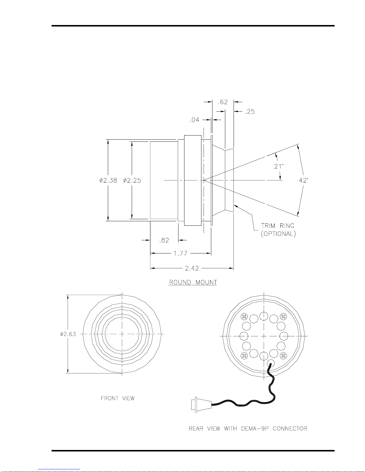
3.1.2 The lighting assembly can be mounted in any location that will allow
the unit to connect with the aircraft lighting system. The selected
location must have an opening prepared for the unit to be inserted
and mounted. Refer to section 6.0 for unit dimensions and
mounting hole locations.
3.1.2 The CL 12/16 Watt Series Cabin Light shall be installed to conform
to the standards designated by the customer, installing agency, and
existing conditions as to the unit location and type of installation.
3.1.4 Mounting screws are required to secure the unit. Refer to Section
7.0, Reference Drawings, for mounting hole diameters and
configuration.
3.2 Unpacking and Inspection
Carefully open the packaging and remove the unit. Verify that all
components have been included in the package per the packing list.
Inspect the unit for damage. Retain the packing materials and packing
list.
If damage has occurred during shipping, a claim must be filed with AI
within 24 hours and a “Return Request Authorization Number”must be
obtained from AI. Refer to the front cover of this manual for address and
telephone number of Audio International. Repackage the unit in its
original packaging materials and return it to AI following instructions given
by the AI representative. If no return is necessary, retain the packing
materials for storage or reshipment if necessary.

Audio International, Inc. CL12/16 Watt Series Cabin Light
Installation & Operations
Document #540037, Rev. B, 4/2000 Page 6 of 11
3.3 Cautions and Warnings
3.3.1 It is important to do a pin-to-pin power and ground check on all
connectors. Ensure that power and ground are applied only where
specified. Damage to the unit may result if power or ground is
applied to the wrong points.
3.3.2 DO NOT connect or disconnect the module while power is applied.
3.3.3 DO NOT remove any factory-installed screws. Damage to the units
may result and void any warranties.
3.3.4 ESD (Electro Static Discharge) guidelines shall be followed.
3.4 Wiring Requirements
3.4.1 Introduction
The installing agency shall supply and fabricate all external cables
and mating connectors. The length and routing of external cables
must be carefully studied and planned before attempting installation
of the units. Allow adequate space for installation of cable and
connectors. Avoid sharp bends and placing cables near aircraft
control cables. Maintain a minimum clearance of three (3) inches
from any control cable. If wiring is run parallel to combustible fluid
or oxygen lines, maintain a separation of six (6) inches between the
lines.
3.4.2 Power Wires
All power and ground wires shall be 22 AWG, minimum. Power
ground wires shall be grounded within twelve (12) inches of the
unit. All wires shall be in accordance with MIL-W-22759 or
equivalent. Twisted, shielded cable shall be in accordance with
MIL-W-27500 or equivalent. Protect power wires with circuit
breakers or fuses located close to the electrical power source bus.
3.5 Physical Characteristics
3.5.1 Refer to Section 6.0 for unit dimensions.
3.5.2 When mounting the unit, allow sufficient space for mating
connectors.
3.6 Electrical Characteristics
3.6.1 The lights may be ordered with or without connectors. Refer to
section 1.2 to determine the connector supplied with the unit.
3.6.2 Refer to section 3.7 to determine pin connections as well as the
lighting options supplied with the unit.

Audio International, Inc. CL12/16 Watt Series Cabin Light
Installation & Operations
Document #540037, Rev. B, 4/2000 Page 7 of 11
3.7 Connector / Mating Connector
Config. Connector Mating Connector
-11 DEMA-9P P/N M24308/4-259F
Female Screwlock P/N M24308/26-1F DEMA-9S P/N M24308/2-281F
Male Screwlock
-12 3-Pin Amp Receptacle P/N 350767-1
Pin P/N 350547-1 3-Pin Amp Plug P/N 350766-1
Socket P/N 350550-1
-21 DEMA-9P P/N M243-8/4-259F
Female Screwlock P/N M24308/26-1F DEMA-9S P/N M24308/2-281F
Male Screwlock
-22 5-Pin Amp Receptacle P/N 3500810-1
Pin P/N 350547-1 5-Pin Amp Plug P/N 350809-1
Socket P/N 350550-1
-31 DEMA-9P P/N M24308/4-259F
Female Screwlock P/N M24308/26-1F DEMA-9S P/N M24308/2-281F
Male Screwlock
-32 3-Pin Amp Receptacle P/N 350767-1
Pin P/N 350547-1 3-Pin Amp Plug P/N 350766-1
Socket P/N 350550-1
-33 2-Pin Amp Plug P/N 1-640507-0
Pin P/N 640545-2 2-Pin Amp Receptacle
P/N 1-640517-0
Socket P/N 641300-2
-51 DEMA-9P P/N M24308/4-259F
Female Screwlock P/N M24308/26-1F DEMA-9S P/N M24308/2-281F
Male Screwlock
-53 6-Pin Amp Plug P/N 1-640510-0
Pin P/N 640545-2 6-Pin Amp Receptacle
P/N 1-640520-0
Socket P/N 641300-2
-61 DEMA-9P P/N M24308/4-259F
Female Screwlock P/N M24308/26-1F DEMA-9S P/N M24308/2-281F
Male Screwlock
-63 6-Pin Amp Receptacle
P/N 1-640510-0
Pin P/N 640545-2
6-Pin Amp Receptacle
P/N 1-640520-0
Socket P/N 641300-2
-71 DEMA-9P DEMA-9S
-73 1-640510-0 w/640545-2 pins
(AMP Part Number) 1-640520-0 w/641300-2 sockets
(AMP Part Number)

Audio International, Inc. CL12/16 Watt Series Cabin Light
Installation & Operations
Document #540037, Rev. B, 4/2000 Page 8 of 11
3.8 Pinout Assignment Descriptions
Config. Lighting Option Pin # Description
1 + 28 VDC
2 Ground
3 On/Off, BRT/DIM, MOM GND Input
-11 Single button On/Off control
And dimmer
4 Emergency Power (+28 VDC)
1 +28 VDC
2 Ground
3 On/Off, BRT/DIM, MOM GND Input
-12 Single button On/Off control and
dimmer
4 Emergency Power
1 +28 VDC
2 Ground
3 On/Off (MOM/GND)
4 Emergency Power
-21 On/Off control and separate
dimmer
5 BRT/DIM (MOM/GND)
1 +28 VDC
2 Ground
3 On/Off (MOM/GND)
4 Emergency Power
-22 On/Off control and separate
dimmer
5 BRT/DIM (MOM/GND)
1 + 28 VDC
-31 On/Off only w/Amp connector 2 Ground
1 N/C
2 Ground
-32 On/Off only w/Amp connector
3 +28 VDC
1 +28 VDC
-33 On/Off only 2 Ground
1 +28 VDC
2 Ground
3 BRT SW Input (GND)
4 DIM SW Input (GND)
-51 2 Button Bright/Dim
(Unit powers up at minimum
brightness)
5 +28 VDC Emergency LTG Input
1 +28 VDC
2 Ground
3 BRT SW Input (GND)
4 DIM SW Input (GND)
-53 2 Button Bright/Dim
(Unit powers up at minimum
brightness)
5 +28 VDC Emergency LightInput
1 +28 VDC
2 Ground
3 On/Off, BRT/DIM MOM GND Input
4 Emergency Power
-61 Single button On/Off and dimmer
5 Slave/Master DIM CTL Input / Output
1 +28 VDC
2 Ground
3 On/Off, BRT/DIM MOM GND Input
4 Emergency Power
-63 Single button On/Off and dimmer
5 Slave/Master DIM CTL Input / Output
1 +28 VDC
2 Ground
3 BRT Switch Input (GND)
4 DIM Switch Input (GND)
-71 2 Button Bright/Dim
(Unit powers up at mid-intensity
brightness)
5 +28 VDC Emergency Light Input
1 +28 VDC
2 Ground
3 BRT Switch Input (GND)
4 DIM Switch Input (GND)
-73 2 Button Bright/Dim
(Unit powers up at mid-intensity
brightness)
5 +28 VDC Emergency Light Input

Audio International, Inc. CL12/16 Watt Series Cabin Light
Installation & Operations
Document #540037, Rev. B, 4/2000 Page 9 of 11
3.8 Post-Installation Test
With the aircraft power turned “ON”, verify all reading / table lights installed
are operational.
4.0 Operations
All units have a single toggle switch to activate/deactivate the unit. Press the
switch button to activate the unit to the “ON”position; press the switch button a
second time to deactivate to the “OFF”position.
5.0 Troubleshooting Guide
5.1 General Troubleshooting Procedures
Many problems can be isolated with the following general techniques:
• To verify power to the unit, recheck +28 VDC is applied to the proper
pins on the unit. Use a voltmeter to verify correct level.
• Reset by removing power from the unit for at least one minute and
reapply power. Verify the problem still exists.
• Recheck all connections to the unit for security. Check all harness
runs for possible pinching. Recheck all pinouts for application
accuracy.
5.2 Troubleshooting
Should difficulties arise in the installation or operation of the unit, contact
AI Product Support for assistance.
6.0 Specifications
Physical Specifications
Dimensions 2.42”Depth x 2.63”Width
6.15cm Depth x 6.60cm Width
Weight 0.38 lbs / 0.17 kg
Electrical Specifications
Power +28 VDC nominal
12W = <500mA
16W = <600mA
Bulb Power 12 or 16 watts
Emergency Power Input +6.3 VDC
Override to full “ON”
+28 VDC active

Audio International, Inc. CL12/16 Watt Series Cabin Light
Installation & Operations
Document #540037, Rev. B, 4/2000 Page 10 of 11
7.0 Reference Drawings
7.1 Round Light Assembly
The following diagrams show the unit dimensions of the round light assembly. All
dimensions are shown in inches.
‘

Audio International, Inc. CL12/16 Watt Series Cabin Light
Installation & Operations
Document #540037, Rev. B, 4/2000 Page 11 of 11
7.2 Square Light Assembly
The following diagrams show the unit dimensions of the square light
assembly. All dimensions are shown in inches.
This manual suits for next models
2
Table of contents