Audio International, Inc. AI-VC-101, -102 Installation Manual
Document # 540116, Rev. B, 09/2001 Page 6 of 9
3.4.2 Power Wires
All power and ground wires shall be 24 AWG, MINIMUM. Power
ground wires shall be grounded within twelve inches of the unit. All
wires shall be in accordance with the standard military specification
of MIL-W-22759 or equivalent. Twisted, shielded cable shall be in
accordance with the standard military specification of
MIL-DTL-27500 or equivalent. Protect power wires with circuit
breakers or fuses located close to the electrical power source bus.
3.5 Physical Characteristics
3.1.4 Refer to Section 5.0 for unit dimensions.
3.1.5 Refer to Section 6.0 for attachment points.
3.1.6 When mounting the unit, allow sufficient space for mating
connectors.
3.6 Electrical Characteristics
3.6.1 Electrical Specifications:
Electrical Power 290mA @ +28 VDC
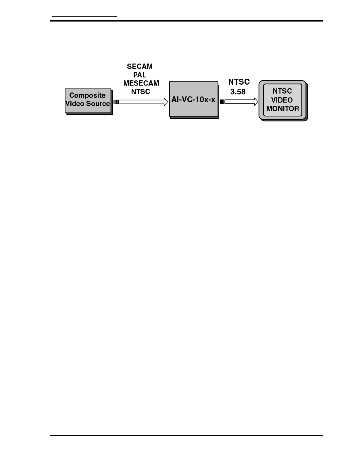
3.6.2 The AI-VC-101, -102 has two BNC connector locations on the rear
of the unit. BNC 1 is designated as video input; BNC 2 is
designated as video output.
3.6.3 The AI-VC-101, -102 requires one (1) 9-pin connector (Positronic
connector for AI-VC-101, and D-subminiature for AI-VC-102). Only
P1 and P2 are connected; all other pins have no connection. Refer
to Section 3.8 for pinout and descriptions.
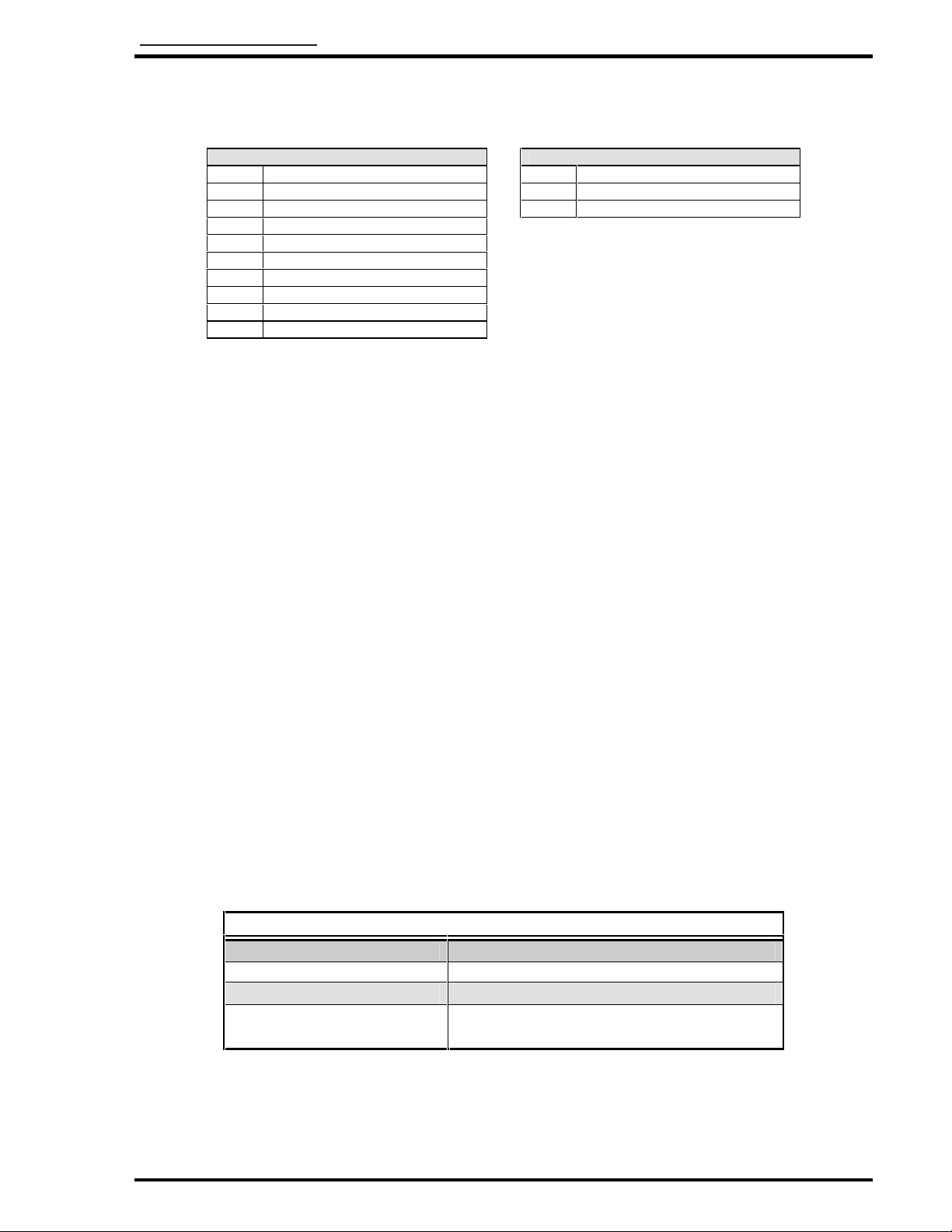
3.7 Mating Connector Information
All wiring harnesses to the unit are supplied and fabricated by the
installing agency.
Model # Mating Connector
AI-VC-101 RD9F10JVLO Positronic
AI-VC-102 DEMA-9S or equivalent Connector
DE24657 Backshell
D20419-18 Female Screwlock
BNC 1 and 2 Amphenol 31-70013 or equivalent