Audio International, Inc. MSM2912-01-x Installation Manual
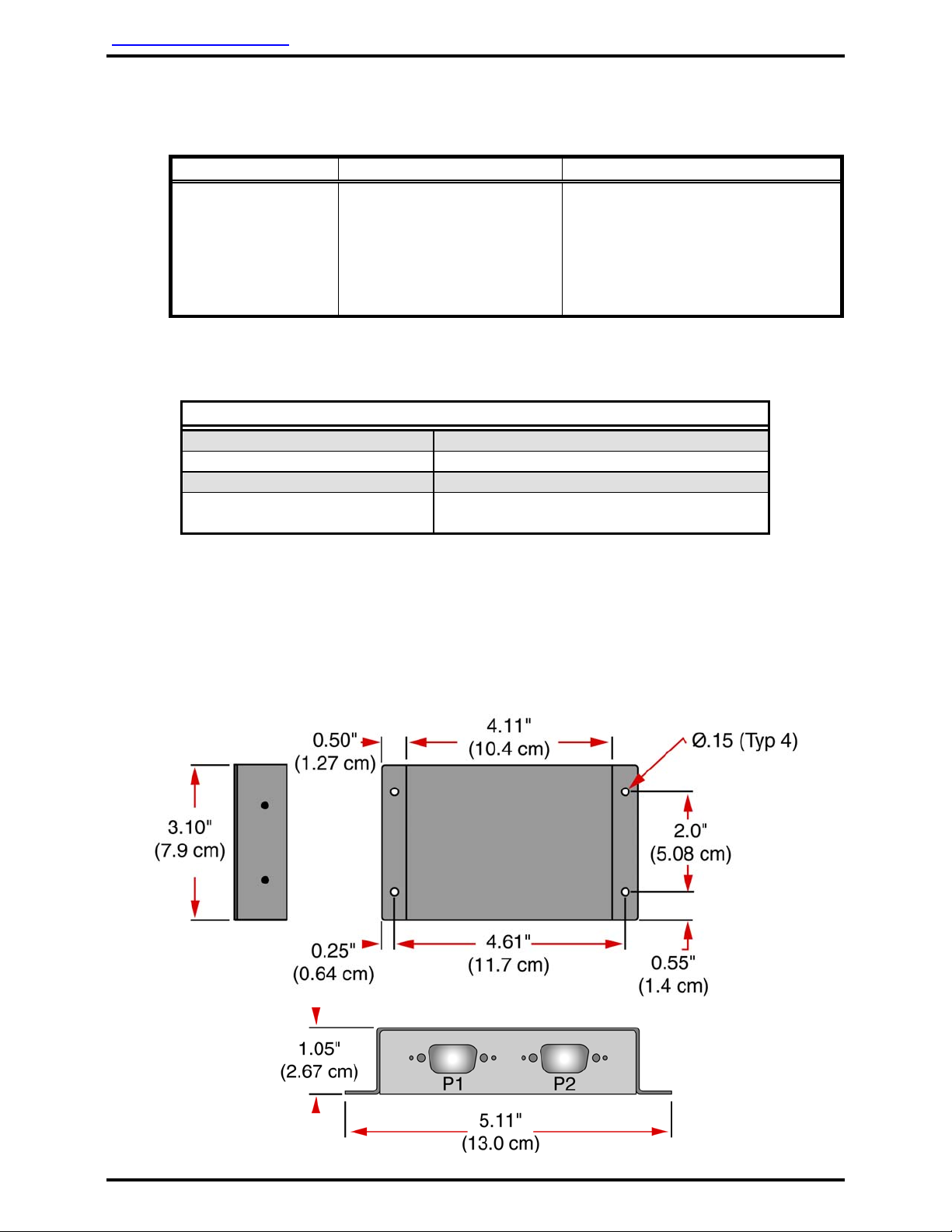
3.8 Pinout Assignment and Descriptions
P1 (RS-232) P2 (RS-485)
Pin # Description Pin # Description
1 Reserved 1 +28 VDC Power Input
2 Receive Data 2 Ground
3 Transmit Data 3 Data Bus A (HI)
4 Reserved 4 Data Bus B (LO)
5 Signal Ground 5 Data Bus Shield
6 Reserved 6 Reserved
7 Reserved 7 Reserved
8 Reserved 8 Reserved
9 Reserved 9 Reserved
3.9 Post-Installation Test
Verify that the data bus conversion commences and appropriate
equipment is operational.
4.0 Troubleshooting Guide
4.1 General Troubleshooting Procedures
Many problems can be isolated with the following general techniques:
• To verify power to the unit, recheck +28 VDC power is applied to the
proper pins on the unit. Use a voltmeter to verify correct level.
• Reset by removing power from the unit for at least one (1) minute and
reapply power.
• Recheck all connections to the unit for security and all harness runs for
possible pinching. Recheck all pinouts for application accuracy.
• Utilizing a voltmeter, oscilloscope, or other voltage instrument, verify
proper input voltage on the data bus pins. Typical measurements with
no device(s) on bus transmitting are as follows:
A-to-Ground : 4.0 to 4.5 VDC
B-to-Ground : 0.1 to 0.2 VDC
If any device is transmitting (i.e., holding bus active), then these typical
measurements would be reversed for the A-to-Ground and B-to-
Ground measurements. This is a helpful troubleshooting tool as this
condition can indicate a data bus lockup.
• The RS-485 data bus is a bi-directional bus that does not have a ‘bus
controller’. The bus uses a differential digital signal transmits only
when commands are entered via switch selection or other system
synchronizing commands. The “A” leg of the bus is HI and the “B” leg
LOW.
Document # 540124, Rev C, 04/2004 Page 8 of 9