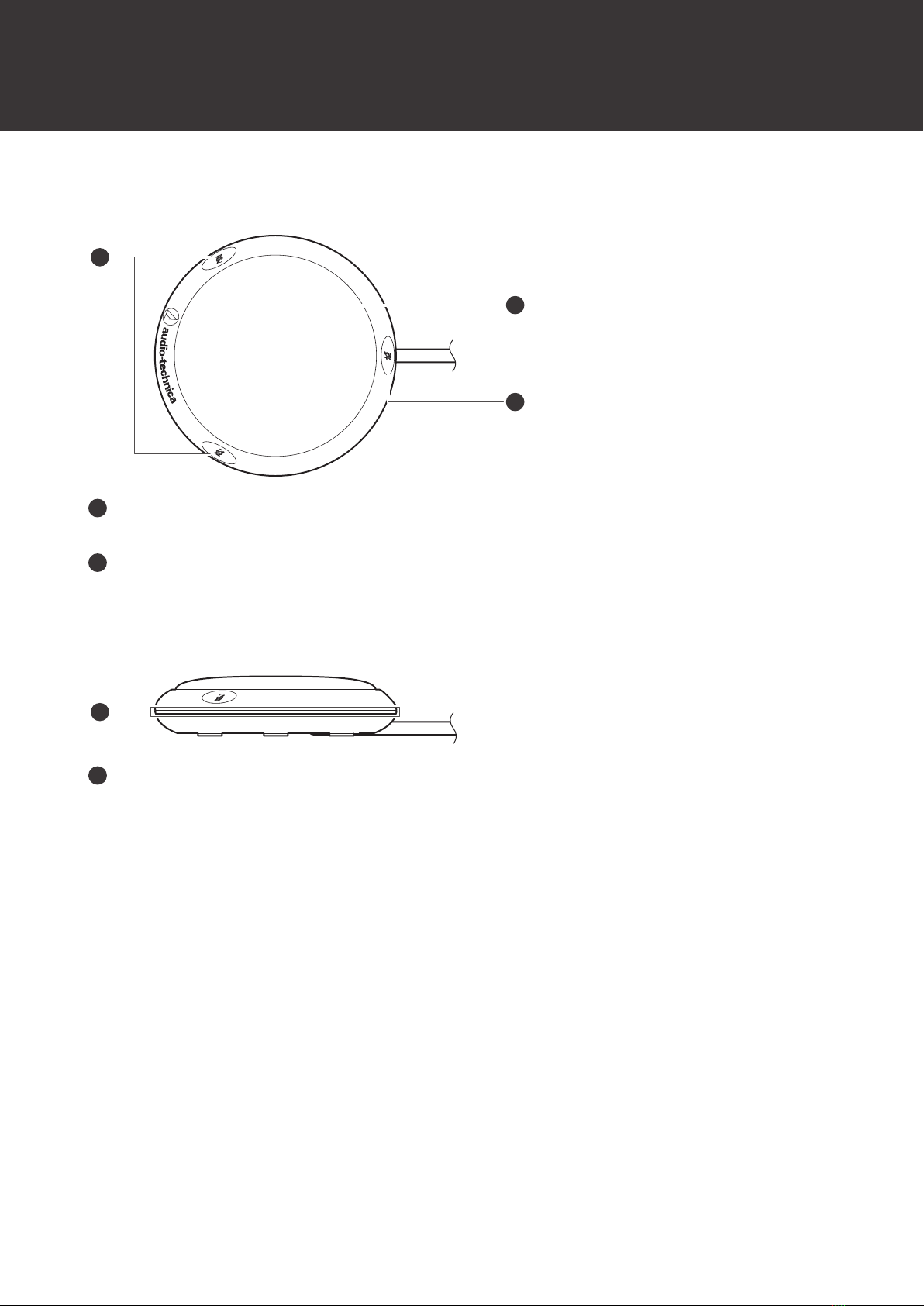
Part names and functions
5
Bottom
SW. FUNCTION
Sets how the talk switches operate.
Mode Operation method
TOUCH ON/OFF Each time you touch a talk switch, the microphone is turned on or off.
MOM. ON
The microphone is turned on as long as you are touching a talk
switch. The microphone is turned off when you stop touching the talk
switch.
MOM. OFF
The microphone is turned off as long as you are touching a talk
switch. The microphone is turned on when you stop touching the talk
switch.
CONTROL
Sets whether the microphone is muted/unmuted and whether the talk indicator lamp is lit by using the product or
the external control device.
Mode Operation
LOCAL
The microphone is muted/unmuted using a talk switch on the
product. The talk indicator lamp also lights in conjunction with talk
switch operation.
REMOTE
The microphone always stays on. The talk indicator lamp lights in
conjunction with the operation of the talk switches, and the operation
information is transmitted to the external control device via the
CLOSURE terminal. The external control device controls
muting/unmuting.
LED REMOTE
The microphone always stays on, and the external control device
controls muting/unmuting and lights the talk indicator lamp. Talk
switch operation information is transmitted to the external control
device via the CLOSURE terminal.