Audio RMS 2020 User manual


88
2
The RMS 2020 System is noted for its ease of use. If
however you need advice or technical support at any
time please contact Audio Ltd.
All products come with free lifetime technical support,
and we are also always pleased to help users of our
equipment, whatever the application.
Audio Ltd,
Audio House
Progress Road
High Wycombe
Bucks, HP12 4JD
U.K.
Tel: +44 (0)1494 511711
Fax: +44 (0)1494 539600
email: [email protected]
World Wide Web: http://www.audioltd.com
Copyright © 1999 Audio Limited
Part no: RMS 2020U/1
This guide was produced by
Human Computer Interface Limited,
http://www.interface.co.uk

88
3
Contents
Introduction 4
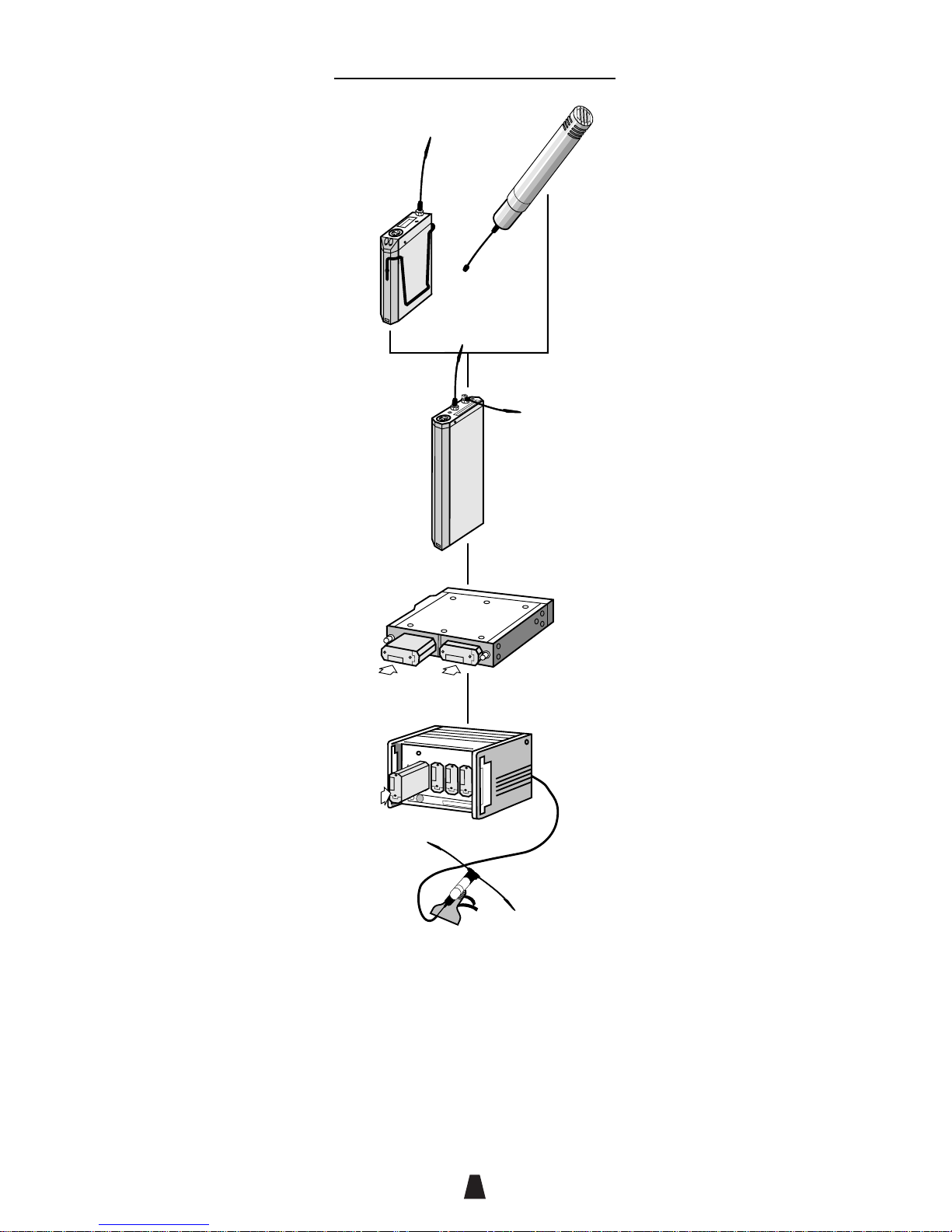
The RMS 2020 System ......................................................... 4
Diversity reception ............................................................... 6
Selecting frequencies ......................................................... 6
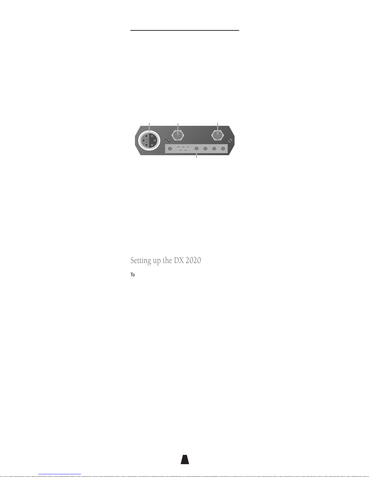
DX 2020 Receiver 7
Controls, displays, and connections ................................. 7
Setting up the DX 2020 ......................................................... 8
Technical specification ..................................................... 10
TX 2020 Pocket Transmitter 11
Controls, displays, and connections ............................... 11
Setting up the TX 2020 ....................................................... 12
Technical specification ..................................................... 13
HX 2000 Hand Held Transmitter 14
Controls, displays, and connections ............................... 14
Setting up the HX 2000 ....................................................... 15
Holding the HX 2000 ........................................................... 16
Technical specification ..................................................... 17
RK␣ 2 Minirack 18
Controls, displays, and connections ............................... 18
Setting up the RK␣ 2 ............................................................. 19
Setting the output phase ................................................... 20
Technical specification ..................................................... 20
DK 2000 Rack 21
Controls, displays, and connections ............................... 21
Setting up the DK 2000 ....................................................... 23
Audio monitoring ................................................................ 24
Bargraph display ................................................................ 24
Technical specification ..................................................... 24
Troubleshooting 25
Cable wiring diagrams 27
Index 30

88
4
CHAPTER
1
Introduction
This chapter gives a general introduction to radio
microphones, and shows how the RMS 2020 Series
products interrelate.
○○○ ○○○○○○○○○○○○○○○○○○○○○
Audio Limited
Audio Limited has been designing and manufacturing
broadcast quality radio microphone systems for over
thirty-five years and over this period they have become
the choice of professional sound mixers around the
world.
Audio Limited’s systems have acquired an acclaimed
reputation for reliability and transparent sound quality
through our commitment to designing products with
maximum input from the customer.
All products designed by Audio Limited are a result of
listening to our customers.
○○○ ○○○○○○○○○○○○○○○○○○○○○
The RMS 2020 System
The RMS 2020 is a 32-channel synthesised diversity
radio microphone system designed to give extremely
clear sound combined with world wide compatibility.
The illustration opposite shows the products in the
RMS 2020 System.
TX 2020
The small battery-powered pocket transmitter for use
with a range of lapel microphones.
HX 2000
A hand-held transmitter for use with a range of high-
quality Schoeps microphone capsules.
DX 2020
The diversity receiver in the RMS 2020 System, it can be
used as a portable receiver, with a camcorder, or
mounted in an RK 2 or DK 2000 rack.
RK 2 Minirack
Allows two DX 2020 receivers to be mounted in a
compact portable rack.

88
5
TX 2020
HX 2000
DX 2020
Receiver
Rk2 Mini-Rack
Receivers
Receivers
DK 2000 Rack
Aerial
Introduction
DK 2000 Rack
Allows up to four DX 2020 receivers to be mounted and
powered in a portable rack, with visual and headphone
monitoring.
All the UHF products from the RMS 2000 range are
directly compatible with the RMS 2020 range.

88
6
○○○ ○○○○○○○○○○○○○○○○○○○○○
Diversity reception
When electromagnetic waves are radiated by a moving
transmitter, the receiver picks up reflected signals from
surrounding structures as well as the directly radiated
signal. These reflected signals combine with the direct
signal, and in the case where the combining signals are
out of phase with each other, a drop-out or loss of signal
results.
To eliminate this cancellation effect Audio Limited
employ the true diversity technique in the DX 2020
receiver.
The DX 2020 receiver incorporates two separate
receivers fed by separate antennae. A comparator
circuit compares the RF levels from the two receivers
ensuring that the receiver will always switch to the
strongest signal. A noiseless switching circuit takes full
advantage of the accurate level detection to allow
switching as often as needed without noise or clicks.
The result is a reliable, dropout free, broadcast-quality
audio signal indistinguishable from a line microphone.
○○○ ○○○○○○○○○○○○○○○○○○○○○
Selecting frequencies
The RMS 2020 System provides a choice of 32 operating
frequencies, in two banks in the UHF 470MHz to
1000MHz range. This gives the flexibility of allowing
several sets of receivers and transmitters to be
operated in the same area without interference.
Introduction

88
7
CHAPTER
2
DX 2020 Receiver
The DX 2020 diversity receiver in the RMS 2020
range can be used, in conjunction with a TX 2020 or
HX 2000 transmitter. Alternatively, up to four DX 2020
receivers can be rack mounted for applications
where multiple wireless microphone systems are
required.
○○○ ○○○○○○○○○○○○○○○○○○○○○
Controls, displays, and connections
Bottom panel
Headphone
level
Battery
compartment RX1
RX2
TX low
battery
RX low
battery No
signal
On
Off
F1
F2
Batteries
Holds three DL123A 3 volt Lithium batteries.
RX1/RX2 indicators
Indicate which of the unit’s two built-in receivers is
active at any time.
TX/RX low battery indicators
Illuminate when the unit detects low battery power in
either the TX 2020 Pocket Transmitter or DX 2020
Receiver. The units should not be used when a low
battery power indicator is illuminated as poor operation
may result.
No-signal indicators
Illuminated when no carrier signal is being received,
such as when the transmitter is switched off or set to an
incorrect frequency.
On/Off
Switches the power on or off. Additionally the output
cable includes a link which disconnects power when
the Lemo plug is removed, in which case the switch can
be left on.

88
8
F1/F2
Selects between the two banks of 16 frequencies; see
Selecting the operating frequency
, page 9.
Headphone level
Adjusts the headphone level output. Use a small
screwdriver to turn the control.
Top panel
Antenna 2
Rack connector
Audio
output Antenna 1
Audio output
Provides balanced microphone level and adjustable
headphone outputs.
Antenna 1/Antenna 2
SMA sockets to which the antennae are connected.
Rack connector
The multiway connector is for use with the DK 2000 and
the RK 2 rack systems.
○○○ ○○○○○○○○○○○○○○○○○○○○○
Setting up the DX 2020
To set up the DX 2020 in conjunction with a TX 2020 or
HX 2000:
• Fit the batteries.
• Set the transmitter and receiver to the same
operating frequency.
• Connect the RX1 and RX2 antennae.
• Switch on.
• Connect the audio output cable.
• Check that one of the RX1 and RX2 indicators is
illuminated, and that the ‘No signal’ indicators are not
illuminated.
These steps are explained below:
Fitting the batteries
To open the battery compartment, press the release
button and flip the cap. Insert three DL123A 3 volt
Lithium batteries, negative contact first as shown on the
side of the unit, and close the cover. Do not use
excessive force.
DX 2020 Receiver

88
9
Selecting the operating frequency
Select the operating frequency you want to use from the
label on the side of the DX 2020. Set the F1/F2 switch to
F1 (first column of frequencies) or F2 (second column of
frequencies). Rotate the switch on the side of the DX
2020 using a small screwdriver to select the frequency, 1
to 16.
Switch the DX 2020 off and back on again to enable the
change in frequency.
Connecting the antennae
Connect the antennae to the SMA connectors marked
RX1 and RX2. Connect the straight antenna to one
socket and the right-angled antenna to the other socket.
Indicators during correct operation
The DX 2020 should switch between the RX1 and RX2
receivers for best reception, as indicated by the RX1
and RX2 indicators:
RX1 RX2
The ‘No signal’ indicators will not be lit if the
corresponding TX 2020 transmitter is on.
External powering
If the DX 2020 receiver is to be externally powered,
ensure that the appropriate cable is used.
DX 2020 Receiver

88
10
○○○ ○○○○○○○○○○○○○○○○○○○○○
Technical specification
Size 147 x 64 x 20mm
Weight 250g
Temperature range -20˚C to +55˚C
Frequency range 470MHz–1000MHz
Number of frequencies 32
Balanced output level -26dBm
Batteries 3 x 3V DL123A Lithium
Battery life Approximately 10 hours
External power 9–14V DC via
6-pin Lemo™ socket
Certified
DX 2020 Receiver

88
11
CHAPTER
3
TX 2020 Pocket
Transmitter
The TX 2020 Transmitter is a small, lightweight,
battery-powered pocket transmitter for use with a
wide range of lapel microphones.
○○○○○○○○○○○○○○○○○○○○○○○○
Controls, displays, and connections
Top panel
0
1
2
3
4
5
6
7
8
9
AntennaGainOn
F1
Off
F2
Overload
indicator
Audio
input LF cut
Audio input
Allows a microphone or line-level input to be connected.
LF cut
Gives approximately 6dB LF cut at 50Hz, to assist in the
reduction of wind noise.
F1/F2
Selects between the two banks of 16 frequencies; see
Selecting the operating frequency
, page 9.
On/Off
Switches the power on or off. Additionally the
microphone cable includes a link which disconnects
power when the Lemo plug is removed, in which case
the switch can be left on.
Gain
Provides eight gain options when used with standard
microphones. 0 gives minimum gain, and each position
increases the gain by approximately 4dB giving a total of
30dB of adjustment. Position 8 and 9 provide line level
input to 600Ωimpedance.
Overload indicator
Indicates the low distortion overload limiter is operating.

88
12
○○○ ○○○○○○○○○○○○○○○○○○○○○
Setting up the TX 2020
To set up the TX 2020 in conjunction with a DX 2020:
• Fit the battery.
• Set the transmitter and receiver to the same
operating frequency.
• Connect the antenna.
• Switch on.
• Connect the microphone.
• Check that the receiver’s ‘No signal’ indicators are
not illuminated.
• Set the microphone gain.
These steps are explained below:
Fitting the battery
To open the battery compartment press the release
buttons at each end of the battery tray and slide out the
tray. Insert a 6LR61 type 9 volt alkaline battery, observing
the polarity as shown on the inside of the tray, and
replace the tray. Do not use excessive force.
An electronic resetable fuse protects the transmitter
from reverse powering. A low transmitter battery
indicator is provided on the DX 2020 Receiver.
Selecting the operating frequency
Select the operating frequency you want to use from the
label on the side of the TX 2020. Set the F1/F2 switch to
F1 (first column of frequencies) or F2 (second column of
frequencies). Rotate the switch inside the TX 2020
battery compartment using a small screwdriver to select
the frequency, 1 to 16.
Switch the TX 2020 off and back on again to enable the
change in frequency.
Connecting the antenna
Connect the flexible antenna to the SMA connector.
Connecting the audio input
Connect the microphone or line level input to the six-pin
Lemo connector. Both positive and negative bias
voltages are provided, enabling the majority of lavalier
microphones to be used with the TX 2020.
TX 2020 Pocket
Transmitter

88
13
Setting the microphone gain
The microphone gain control should be adjusted to suit
your particular requirements. Select the gain position
such that the overload indicators do not illuminate
during normal speech.
○○○ ○○○○○○○○○○○○○○○○○○○○○
Technical specification
Size 87 x 60 x 21mm
Weight 115g
Temperature range -20˚C to +55˚C
Frequency range 470MHz–1000MHz
Frequency stability Better than ETS 300–422
Number of frequencies 32
Output power 50mW nominal
Gain control range 30dB in 8 steps, plus 2 steps for
600Ωline input
Maximum input level -6dBm (position 7)
+6dBm (position 8, 600Ω)
Frequency response 50Hz to 15kHz ±1dB
THD <0.1% at working levels
<0.3% at gain position 7 with
-6dB input in overload
Battery 1 x 9V 6LR61 Alkaline
Battery life More than 6 hours.
Certificate No. 13148
TX 2020 Pocket
Transmitter

88
14
CHAPTER
4
HX 2000 Hand Held
Transmitter
The HX 2000 is a hand held transmitter for use with
the DX 2020 diversity receiver. It provides two
switchable frequencies, and can be used with a
range of microphone capsules from the Schoeps
Colette series.
○○○ ○○○○○○○○○○○○○○○○○○○○○
Controls, displays, and connections
,,,,,,,,,,,,
,,,,,,,,,,,,
yyyyyyyyyyyy
yyyyyyyyyyyy
0
1
2
3
4
5
6
7
8
9
F2
Gain
F1
Power locking
ring
Battery
compartment
Antenna
Overload
Flat
Microphone
capsule
LF cut
Operation
Microphone capsule
Compatible with the full range of capsules and
accessories in the Schoeps Colette range.
LF cut
Gives approximately 3dB LF cut at 100Hz and an
additional 6dB per octave below this, to assist in the

88
15
reduction of wind noise.
Gain
Provides ten gain options; 0 gives minimum gain, and
each position increases the gain by approximately 4dB
giving a total of 40dB of adjustment.
Operation indicator
Indicates amber when the unit is on and the battery
voltage is within the working range. The indicator will go
out when the battery voltage is low; although the HX
2000 will continue to operate for a short time after this,
the battery should be replaced as soon as possible.
Overload indicator
Indicates that the low-distortion overload limiter is
operating.
F1/F2
Selects between the two available operating
frequencies; see
Selecting the operating frequency
below.
Power locking ring
Locks the battery compartment to prevent accidental
switching off while in use.
Battery compartment
Holds one DL123A 3 volt Lithium battery.
Antenna
The optional antenna screws in the base of the battery
compartment.
○○○ ○○○○○○○○○○○○○○○○○○○○○
Setting up the HX 2000
To set up the HX 2000 in conjunction with a DX 2020:
• Fit the battery.
• Set the transmitter and receiver to the same
operating frequency.
• Connect the antenna (optional).
• Switch on by turning the battery compartment until
the operation indicator lights up.
• Lock into position with the locking ring.
• Set the gain.
• Check that the receiver’s ‘No signal’ indicators are
not illuminated.
HX 2000 Hand Held
Transmitter

88
16
These steps are explained below:
Fitting the battery
Unscrew the battery compartment and insert a DL123A
type Lithium battery with the positive end uppermost.
Replace the battery compartment.
Selecting the operating frequency
Set the F1/F2 switch to select the operating frequency.
The two available operating frequencies are marked on
the label above the battery compartment.
Connecting the antenna
Screw the antenna directly into the base of the battery
compartment. For short-range work the antenna can be
omitted, as the battery compartment acts as an antenna.
Switching on
To switch on unscrew the locking ring, and then screw
the battery compartment up tight so that the amber
operation indicator lights up. Then screw up the locking
ring to prevent the user from inadvertently unscrewing
the battery compartment during use.
When not in use the power should be locked off by
unscrewing the battery compartment and then
tightening the locking ring. Remove the battery if the unit
is not to be used for a while.
Setting the gain
The gain control should be adjusted to suit your
particular requirements. Select the gain position such
that the overload indicator does not illuminate during
normal speech.
○○○ ○○○○○○○○○○○○○○○○○○○○○
Holding the HX 2000
The HX 2000 should be held by the main tube, which is
finished in gloss black to minimise handling noise.
Avoid touching the areas finished in matt black, and in
particular the battery compartment as this forms part of
the antenna.
HX 2000 Hand Held
Transmitter
The HX 2000 handheld transmitter does not transmit the
low TX battery level, consequently the low TX battery
indicator on the receiver will remain on. This is not a
fault.

88
17
○○○ ○○○○○○○○○○○○○○○○○○○○○
Technical specification
Length 220mm including capsule
Diameter 20mm reducing to 18mm at base
Weight 130g
Temperature range -20˚C to +55˚C
Frequency range 140MHz–1000MHz
Number of switchable 2
frequencies
Output power 10mW nominal
Gain control range 40dB in 10 steps
Frequency response 50Hz to 15kHz ±1dB excluding
capsule
THD <0.3% at 1kHz in overload
Battery 3V DL123A Lithium
Battery life Approximately 6 hours
Certificate No. 11985
HX 2000 Hand Held
Transmitter

88
18
CHAPTER
5
RK 2 Minirack
The RK 2 Minirack allows you to mount two DX 2020
or DX 2000 diversity receivers in one portable unit. It
includes a built-in active distribution amplifier, with
approximately 3dB of gain, to allow up to two
receivers to be fed from a single pair of antennae
mounted on the rack. The RK 2 uses the same
antennae as the individual receivers.
○○○ ○○○○○○○○○○○○○○○○○○○○○
Controls, displays, and connections
Side panel
,,,
,
,
,
,
,
,
,,,
yyy
y
y
y
y
y
y
yyy
Antennae
Power
input
LH Receiver
Audio output
RH Receiver
Audio output

88
19
Audio output
Provides microphone-level balanced outputs from the
two receivers.
Power input
Allows the receivers to be powered via an external DC
supply.
Antennae
Connects the Rx1 and Rx2 antennae.
Front panel
The indicators and controls of each receiver are visible
from the top of the RK 2 rack. For more information see
DX 2020 Receiver
, page 7.
○○○ ○○○○○○○○○○○○○○○○○○○○○
Setting up the RK 2
To set up the RK 2 in conjunction with one or two DX
2020 receivers:
• Fit the receivers into the RK 2.
• Connect external power.
• Connect the antennae.
These steps are explained below:
Fitting the receivers
To fit the individual receivers into the RK 2 first remove
the plastic plate covering the multipin connector on
each receiver. Orientate the receiver to ensure correct
alignment of the Lemo and multipin connectors. Slide
the receiver in, and push firmly home. Do not use
excessive force.
Connecting power
Connect power to the four-pin Hirose connector via the
cable provided (900–122). Alternatively the RK 2 can be
powered via either of the six-pin Lemo connectors.
The RK 2 has a built-in regulator and can accept power
in the range 9–15V DC. It is over voltage and reverse
power protected; if reverse power is accidentally
applied disconnect the supply and allow a few moments
for the electronic fuse to reset.
Rk2 Minirack

88
20
Connecting the antennae
Connect the antennae to the SMA sockets marked Rx1
and Rx2 on the front panel. Connect the straight antenna
to one socket and the right-angled antenna to the other
socket.
○○○ ○○○○○○○○○○○○○○○○○○○○○
Setting the output phase
The RK 2 is factory set to provide outputs of the same
phase as the individual receivers. Should opposite
phase be required reset the DIP switch positions as
shown in the following diagrams:
0°Phase 180°Phase
1
ON
234 1
ON
234
○○○ ○○○○○○○○○○○○○○○○○○○○○
Technical specification
Size 168mm (+12mm connector block)
x 151mm x 30mm
Weight 650g
Frequency range To order
Gain Typically 2–4dB across range
Power 9–15V at 80mA plus 140mA per
receiver, with reverse power and
over voltage protection up to 30V.
Rk2 Minirack
Table of contents