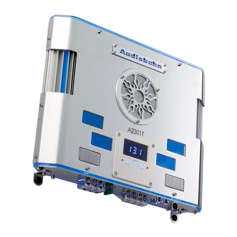
AudioBahn A2201Q User manual


her.. .
25
ducts at.. .
bc.com
Table of Contents
.-~.~--_.~.
INTRODUCTION .................................................................................................................... 3
FEATURES AND SPECIFICATIONS ................................................................................. ,4
CONTROLS AND FUNCTIONS ..................................................................................... 5-14
A2201Q/A2301Q/A2401Q/A2601Q/A2801QIA3201Q ......................................................... ...5
A44OlQ/A46OlQ ................................................................................................................... .
A6601Q ................................................................................................................................ .
A1801Q ................................................................................................................................ .
PLANNING I MOUNTING YOUR SYSTEM ................................................................... ,151
WIRING DIAGRAMS ..................................................................................................... .16-22
A1801Q ............................................................................................................................ ...16
A2201Q/A2301Q/A2401Q/A2601QIA2801Q/A3201Q ................................................... ..16- 17
A4401Q/A4601Q ....................................................................................................... ...18-19
A66OlQ ....................................................................................................................... ..20-2 2
ADJUSTMENTS AND TUNING ........................................................................................ 23
TROUBLE SHOOTING ....................................................................................................... ,24
WARNING/DISCLAIMER ................................................................................................... ,25
WARRANTY .......................................................................................................................... 26
2

Introduction
”----. “.--“- .----.“-.“. ^..- ---- --I ” .
Thank you for purchasing an Audiobahn A/B Power Amplifier
specifically designed for the mobile environment. This manual contains
important information about installation, set-up procedures and intergrading
this amplifier into your car stereosystem.With proper care and installation,
your new audiobahn A/B Mosfet Power amplifier will provide you with
many years of high performance listening enjoyment.
Before making any electrical connections, Make sure that vou disconnect the
battery’s ground cable toprevent thepossibility of short &wits or damage to
your electronic equipment. (rJ’your stereo hasan Anti-th# codeDO NOT
disconnect the battery).
Features and Specificatioln
.‘ “““.
e Class A/B Mosfet Power Amplifier
e 2 Ohm Stable Stereo
Q 4 Ohm Stable Mono
e Full Mosfet Power Supply
@Non Regulated Power Supply
@Double Sided Circuit Board
0 Interior Circuit Board llluminatior
e Blue LEDVolt Meter*
0 Fan Cooled
* 18dB BassBoost
l
Soft Start Circuitry
l
Variable Sub Sonic Filter 20-50H.
* Signal ToNoise Ratio: 1OOdB
* High Quality Bipolar Audio Stagt
Recommended Fuse Size
. A2201Q
* A2301Q
* A2401Q
* A2601Q
e A2801Q
. A3201Q
* A4401Q
l
A4601Q
* A6601Q
@A1801Q
2OAx 1
25Ax 1
30Ax 1
20Ax2
30Ax2
4OAx2
30Ax 1
2OAx2
3OAx2
2OAx2
Power Output -_
“.._”.,^-x_I.
. A2201Q 50 watts x 2 @ 4 ohm
. A2301Q 75 watts x 2 @ 4 ohm
l
A2401Q lOOwattsx2@4ohr
. A2601Q 150 watts x 2 @ 4 ohr
. A2801Q 200 watts x 2 @ 4 ohr
. A3201Q 300 watts x 2 @ 4 ohr
. A4401Q 50wattsx4@4ohm
. A4601Q 75wattsx4@4ohm
e A6601Q 75wattsx6@4ohm
l
A1801Q 400 watts x 1 @ 4 ohr
3

nA/B Power Amplifier
ment. This manual contains
-up procedures and intergrading
5th proper care and installation,
Wier will provide you with
Ijoyment.
fake sure that vou disconnect the
ility
qf
shovt c&cuits or damage to
7san Anti-th$ code DO MOT
B Class A/B Mosfet Power Amplifier
e 2 Ohm Stable Stereo
e 4 Ohm Stable Mono
0 Full Mosfet Power Supply
@ Non Regulated Power Supply
e Double Sided Circuit Board
0 Interior Circuit Board Illumination
0 Blue LED Volt Meter*
0 Fan Cooled
0 18dB Bass Boost
l
Soft Start Circuitry
l
Variable Sub Sonic Filter 20-5OHz**
l
Signal To Noise Ratio: 1OOdB
e High Quality Bipolar Audio Stage
. A2201 Q : 20A x 1
. A2301 Q : 25A x 1
0 A2401Q: 3OAx 1
. A26OlQ: 2OAx2
* A28OlQ:3OAx2
* A3201Q: 4OAx 2
e A44OlQ: 3OAx 1
* A46OlQ:2OAx2
0 A66OlQ:3OAx2
* Al8OlQ: 2OAx2
Power ~~~~~~
“..^ .
. A2201 Q : 50 watts x 2 @ 4 ohms
l
A2301 Q : 75 watts x 2 @ 4 ohms
l
A24OlQ: lOOwattsx2@4ohms
l
A26OlQ: 15Owattsx2@4ohms
l
A2801 Q : 200 watts x 2 @ 4 ohms
l
A3201 Q : 300 watts x 2 @ 4 ohms
l
A44OlQ:5Owattsx4@4ohms
l
A4601 Q : 75 watts x 4 @ 4 ohms
o A6601 Q : 75 watts x 6 @ 4 ohms
o Al 801 Q : 400 watts x 1 @ 4 ohms
-_l_ll_,_^,~-_---l--.-_ll.“...l-^l~ ~
. A22OlQ : 2.2” (H) x 12.7” (W) x 8” (D)
. A2301 Q : 2.2” (H) x 12.7” (W) x 8.8” (D)
. A2401 Q : 2.2” (H) x 12.7” (WI x lo” (D)
. A2601 Q : 2.2” (H) x 12.7” (WI x 11.6” (D)
. A28OlQ : 2.2” (H) x 12.7” [WI x 15.1” (D)
. A32OlQ : 2.2” (H) x 12.7” (WI x 17.1” (D)
l
A4401 Q : 2.2” (H) x 12.7” (W) x 11.2” (D)
. A4601 Q : 2.2” (H) x 12.7” (W) x 12.6” (D)
. A66OlQ : 2.2” (H) x 12.7” (w) x 17.1” (D)
l
A18OlQ: 2.2”(H)x12.7”(W)x 15.1”(D)
Controls and Functions
-~- _-_-
5
0
-7
0 0
0
0
8
0 0
0
3
0
.--
0
0 0
0
li
0
Controls and Functions
[I
x c!
1
,f f
;::I
Q
0 0
0
8
.

A4401 Q/A4601 Q REAR
A4401 WA4601 Q FRONT
ah -
7 9
8 (

Controls and Functions
____.~-~~~-. _. Controls and Functions
.I-XIIII1...l“__^~.”

Controls and Functions
_..------. I” I. ,_

Controls and Functions ___..._“-..-.~-“---.--....--. - ~..~. .- _._-----~ -8
A4401Q j
A4601Q :
;-------------.---------.------------------------------~--------------~~~- ,
_ _ _ _ _’
A1801Q ;
.____________.._________________________~--~-----------------------------~-----.
GAIN
CONTROL
0
@
GN &
A2201 Q / A2301 Q i
A2401 Q / A2601 Q :
A2801Q/A3201Q a
A4401Q/A4601Q:
A6601 Q / Al 801 Q I
-------------~----------~--------------~----------.-.-----------~----------.--~
This control adjusts the amplifiers input sensitivity. Input sensitivity is variable from 200 Millivolts
to 7 volts. Clockwise increases sensitivity Counterclockwise decreases sensitivity.
This knob is not a volume control for the amplifier. The amplifier can be driven to full power
with a wide range of signal levels. A lower signal level will require increased sensitivity for full
power. A higher signal level will require decreased sensitivity.
9
_ _ .-. e ,-.-. -.
Controls and Functions
_- ” .._-._.
___
I_____________--___________________
These inputs are for signal cables
frm
cables.
I__________________________________
The LINEOUTallows you to build multipll
to distribute the signal. Now it is simple 1
amplifier, then using the line out RCA ja
-~---...............--~---~-------
By using the bass boost function, bass
nm
FULL
-$j
___--. .___--_-.
,__-
______
Adjust the crossover for your chosen ins
- LPF: Low pass filter-only bass tones (i
Use with woofer or sub-woofer.
- FULL: No filter-all tones go to speaker!
- HPF: High pass filter-blocks very low 1
from the speakers.
x-c

Controls and Functions
l~-,ll”.“” _,-_. _ ._I”. --” --_.... . “l_-. -
I
A4401Q j
A4601Q :
____________________-------------~
A1801Q ;
._________________________________
_________-______-________________,
-”
A2201Q/A2301Q i
A2401Q/A2601Q:
A2801QIA3201Q 0
A4401Q/A4601Q:
A6601Q/A1801Q;
._____________--___----~.--~------
.rtsensitivity is variable from 200 Millivolts
:kwise decreases sensitivity.
!amplifier can be driven to full power
,Iwill require increased ~~nsitivi~ for full
tnsitivity.
1...................---~---~-------------------------~-------~------~----~-----,
These inputs are for signal cables from the source. Always use high quality shielded RCA
cables.
LINE OUT LINE OUT
LEFT
CHI
HGHT A1801Q : A4401Q i
CM A46018 :
I_________._____________________________I_____________-___-_____-____--_----.---,
The LINEOUTallows you to build multiple amplifier systems without having to use splitter cords
to distribute the signal. Now it is simple a matter of bringing one set of RCAS into the first
amplifier, then using the line out RCA jacks as the feed to the next amplifier.
BASS
BASS
BASS
BOOST $a~ !
BOOST
BOOST
By using the bass boost function, bass notes at 50 Hzare emphasized as much as 18dB.
‘-Fan--*------------- ,---------------*------------------
X-OVER A2201Qi X-OVER i X-OVER X-OVER i
________________________________________-----------------------------.--.-----~
Adjust the crossover for your chosen installation method.
- LPF: Low pass filter-only bass tones (50Hz-120Hz/50Hz-500Hz:A6601 Q) go to speakers.
Use with woofer or sub-woofer.
- FULL: No filter-all tones go to speakers. Use with full-range speakers, or with external crossovers.
- HPF: High pass filter-blocks very low tones (50Hz-750Hz/50Hz-500Hz:A6601 Q)
from the speakers.
10

Controls and Functions
-_.- ~..---..,_ .._. . .~ .
POWER
,--.
A2201Q ;
E% :
A2601Q ;
A2801’d s
-pm& :
;,ggg :
A1801Q :
________________________________________----------~---~----~~~-----~---~-----~~
To avoid unwanted ignition noise caused by ground loops, it is essential that the Amplifier
be grounded to a clean, bare, metal surface of the vehicles chassis.
Note: GROUND WIRESHOULDNOT BEEXTENDEDMORE THAN3 FT(1 METER].
POWER ,--_
A2201Q j
GND REM /‘BATI ‘\
.___________________--.-----------------------------------~~-----------~---~---,
Due to the power requirements of the Amplifier, this connection should be made directly
to the positive (+)terminal of battery. For safety measure, install an in-line fuse Holder
(not included)as close to the battery positive (+) terminal as possible with an ampere
rating ; not to exceed total value of fuses in Amp.
POWER
,--w
REM ‘WD
I_______________________________________------------------~~---~---~-
To remote wire car stereo.
Thisamplifier is turned “ON” remotely when vehicle’s stereo is turned “ON”
Note:
IF YOURRADIO DOES NOT HAVE + 12 VOLTOUTPUTLEAD WHEN THERALXOIS TURNEDON,
THE‘REMOTE” TERMINALON THEAMPLIFIERCAN BECONNECTED JO VEHICLESACCESSORY
C/RCU/T THATISLIVEWHEN THEKEYIS “ON”.
Controls and Functions
^- -_-_--- -^
.
FI
I__________________________________
Variable Low-Pass Filter (50Hz-‘I 2OHz) :
filter switch to “LPF”.Adjust variable cr(
The amplifier input circuit filters out ev
adjustment of the frequency control),
5(
__--__-___-___-___________________
Variable Low-Pass Filter (50Hz500Hz) :
filter switch to “LPF”.Adjust variable crt
The amplifier input circuit filters out ev
adjustment of the frequency control),
51
____________________--------------
Variable High-Pass Filter (50Hz-750Hz)
channel, set filter switch to “HPF”.The
below 50Hz ....... 750Hz.
._________________________________
Sub Sonic Switch : ON and OFF
Sub Sonic Variable : 20Hz-50Hz
11

Controls and Functions
_______
_________.
loops, it is essential
vehicles chassis.
___________’
.___.
that the Amplifier
?ETHAN 3 FT[I METER).
,________________________________
A2201Q :
\ \\
I
I
I
I
,
__________________-_____________1
connection should be made directly
ssure, install an in-line fuse Holder
,minal as possible with an ampere
________________________________________------------
LPF
FREQUENCY
A2201 Q/A2301 Q
A2401 Q/A2601 Q j
A2801 Q/A3201 Q ;
0
A4401 Q/;‘WI; ‘GQ :
,_______________________________________--------------------~---~--------------,
Variable Low-Pass Filter (50Hz-‘I 20Hz) : For use as a dedicated subwoofer channel, set
filter switch to “LPF”.Adjust variable crossover frequency with control as desired.
The amplifier input circuit filters out everything above 50Hz . . .. 120Hz (dependent on the
adjustment of the frequency control), so only the deepest bass notes are amplified.
_____-_.___.__--___-.-------------------------------
LPF
FREQUENCY
0 8
50: l
500Hz
A6601Q :
________________________________________----------.-----------------~---------~
Variable Low-Pass Filter (50Hz500Hz) : For use as a dedicated subwoofer channel, set
filter switch to “LPF”.Adjust variable crossover frequency with control as desired.
The amplifier input circuit filters out everything above 50Hz 500Hz (dependent on the
adjustment of the frequency control), so only the deepest bass notes are amplified.
__-_---___-___-___-_____________________-----~--.---
HPF
FREQUENCY
,________________________________(
j stereo is turned “ON”
FAD WHEN THE/MD/O IS TURNEDON,
ZONNECTED ro VEH/CLESACCESSORY
A2201 Q/A2301 Q i
A2401Q/A2601Q ;
A2801 Q/A3201 Q
A4401 Q/A4601 Q :
a
1.-...-........-..-.....................--------------------------------------~
Variable High-Pass Filter (50Hz-750Hz) : For use as a dedicated mid high range
channel, set filter switch to “HPF”.The input circuit filters out all frequencies
below 50Hz ....... 750Hz.
__-___________-___-_____________________----
r SUBSONIC
.________-______________________________------------------------“-----------
Sub Sonic Switch : ON and OFF
Sub Sonic Variable : 20Hz50Hz

Controls and Functions
-x__-,___-,-. .-. I.- ,-.._.-.._
________________________________________--------~-~-------
X-OVER
FREQ.
,
50Hz 5OOHz A6601Q i
________________________________________------------~-------------~---~---~----~
Variable X-OVER FREQ(50Hz to 500Hz): For use as a dedicated subwoofer channel, set
filter switch to “X-OVERFREQ.”Adjust variable crossover frequency with control as desired.
The amplifier input circuit filters out everything above 50 ...500 Hz (dependent on the
adjustment of the frequency control], so only the deepest bass notes are amplified.
________________________________________--------------
INPUT
6CH 4CH
A6601Q !
SWITCHPOSITION INPUTSOURCE
CHl CH3 CH5
CH2 CH4 CH6
, I
A1801Q :
________________________________________------------------~--~-----------------~
PHASESHIFTSWITCH(0 AND 180 DEGREES):Allows you to change the phase of your
subwoofer from 0 and 180 degrees to help compensate for timing differences between
drivers.
i
!
Controls and Functions
A2:
I__________________________________
-PWR (Power) : This BLUELEDwill illumil
illuminate, check the power connec
-PROT( Protection) : The amplifier prot
overload, short circuit or extremely hi!
protection mode is in operation, the
1
indicating the amplifier has gone into
If you observe that the Protection
LED
what has caused the protection circa
the remote power off and then on ag
overload condition, please allow it tc
down because of an input overload
before attempting to power up the a
13
‘...

I
A6601Q :
,_______________________________I
dedicated subwoofer channel, set
,er frequency with control as desired
e 50 ...500 Hz (dependent on the
repest bass notes are amplified.
A660lQ :
._____-___-___-___--_____________
:EI 1 OUTPUT 1
I
<’
Controls and Functions
“- --~X.“...X-.--.-.X--.“.-.~II....- “._- .I.x---..-
0 ;;g;g i
PROT ymg : PWR PROT
0
A2801Q :
PWR A3201 Q : 00
yw;QQ :
A1801Q : A66OlQ ;
‘..............-....--------------------~------~-----------.----~--.--~--------.
-PWR (Power) : This BLUELEDwill illuminate when the amplifier is turned “ON”. If it fails to
illuminate, check the power connections to the Amplifier and fuses.
-PROT( Protection] : The amplifier protection circuitry will disable the amplifier if input
overload, short circuit or extremely high temperature conditions are detected. When the
protection mode is in operation, the LEDindicator on the side panel will be illuminated,
indicating the amplifier has gone into a self-preservation mode.
If you observe that the Protection LEDis lit, please check the system carefully to determine
what has caused the protection circuit to engage. The amplifier can be reset by turning
the remote power off and then on again. If the amplifier shut down due to a thermal
overload condition, please allow it to cool down before restarting. If the amplifier shut
down because of an input overload or short circuit, be sure to repair these conditions
before attempting to power up the amplifier again,
A1801Q i
_________________________________
J
to change the phase of your
nsate fer timing differences between

Planning and Mounting Your System ---”-.---- __I__.
The mounting position of your Amplifier will have a great effect on its ability to dissipate
the heat generated during normal operation.
It has an ample heat sink for heat dissipation, and also designed with a thermal shut-
down (for heat protection) circuit. DO NOT enclose the amplifier in a small box or
cover it so that air can not flow freely.
Temperatures in car trunks have been measured as high as (155’ C) in the summer time.
since the thermal shut-down point for the amplifier is (158’ C) it is easy to see that it must
be mounted for maximum cooling capability. To achieve the maximum advantage of
convection air flow in an enclosed trunk, mount the amplifier in a horizontal position.
Cooling requirements are considerably relaxed when mounting inside the passenger
compartment since the driver will not often allow temperatures to reach a critical point.
Floor mounting under the seat is usually satisfactory as long as there is at least 1 inch
of clearance (2.54 cm) above the Amplifier’s fins for ventilation.
a. Select a suitable location that is convenient for mounting, is accessible for wiring.
And has ample room for air circulation and cooling.
b. Use the amplifier as a template to mark the mounting holes. Remove the Amplifier
and drill holes. Use extreme caution, inspect underneath surface before drilling!
c. Secure the Amplifier using the screws provided.
Al8OlQ
ll____l,”.._-.-.““-.- .- _^
A2201Q/A2301Q/A240lQ/A:
___I~___
~ __.__---“. .,..”I.. -“-
LEFT SPEAKE
2-8 OHM
15
-.P

great effect on its ability to dissipate
also designed with a thermal shut-
?the amplifier in a small box or
s high as (155’ C) in the summer time.
is (158’ C) it is easy to see that it must
thieve the maximum advantage of
e amplifier in a horizontal position,
ten mounting inside the passenger
emperatures to reach a critical point.
y as long as there is at least 1 inch
or ventilation.
mounting, is accessible for wiring.
lling.
.rnting holes. Remove the Amplifier
rderneath surface before drilling!
2-8 OHM
A2201Q/A2301Q/A2401Q/A2601Q/A2801Q/A3201Q
““llll_ll--- l__l.-__-.. I- .II-- ,---- Ix”_~
LEFT SPEAKER RIGHT SPEAKER
2-8 OHM 2-8 OHM

great effect on its ability to dissipate
also designed with a thermal shut-
?the amplifier in a small box or
s high as (155’ C) in the summer time.
is (158’ C) it is easy to see that it must
thieve the maximum advantage of
e amplifier in a horizontal position.
ren mounting inside the passenger
emperatures to reach a critical point.
y as long as there is at least 1 inch
or ventilation.
mounting, is accessible for wiring.
lling.
Jnting holes. Remove the Amplifier
rderneath surface before drilling!
A1801 Q “- -..I.._--_-.-,I .“_--, ~~.
A2201QlA2301 Q/A2401 Q/A26OlQ/A280l Q/A3201 Q
-~_-_-~-_l_ .- -l-~._.“...~ -~~
SUB WOOFER
4-8 OHM
LEFT SPEAKER RIGHT SPEAKER
2-8 OHM 2-8 OHM
16

-.-..,.,-
A2201Q/A2301Q/A2401Q/A26OlQlA28OlQXlA320
-.-_ ..--.“_._..“^_.
m--- _---_-----___-__________________________-----
./a
1Q. .I-, ._“~.
_________________
SUB WOOFER
4-8 OHM
0 LEFT 0 0 RIGHT0
LEFT SPEAKER RIGHT SPEAKER
4-8 OHM 4-8 OHM
i + : INDUCTORLOW PASSFILTER
: --I i- : CAPACITORHIGH PASSFILTER
I_________--___-._______________________---.----------.----~---------~------~--,
TRIMODE OPERATIONALOUTPUTallows a Speaker to be operated in MONO mode while the
main speakers are playing in Stereo. Leave the Crossover (Sub-woofer) switch on “Full”
position. Use a 100 Volt, non polar capacitor for a high pass crossover and a wire coil
(inductor) to block high frequencies from the (Sub) Woofer as shown in the figure below.
Capacitor and inductor values as written in the section below determine crossover
frequencies.
COMPONENT VALUES FOR 6 dB PASSIVE CROSSOVER
FREQUENCY INDUCTOR
80 Hz 7.5 mH
100 Hz 6.5 mH
CAPACITOR
470 UF
330 UF
120 Hz 5.5 mH 330 UF
150 Hz 4mH 220 UF I
BRIDGED
4-8 OHM
@----I
8 CHl0
CHI
2-8
CH3
2-8
17

8OlQXlA3201Q ,”-.,---l_-)(,...
SUB WOOFER
4-8 OHM
SPEAKER
3-8 OHM
be operated in MONO mode while the
ssover [Sub-woofer) switch on “Full”
ligh pass crossover and a wire coil
Noofer as shown in the figure below.
tion below determine crossover
A4401 Q/A4601 Q
-------l^-l .. I. . “. ..-. .1 ...I. ..-..-.l..l-.--lllll-~
BRIDGED
4-8 OHM
SPEAKER
0 - BRIDGED~ e
0 cm 0 e
CH2
8
________________________________________-~~--------------
SUB WOOFER
CH3 CH4
4-8 0 8 OHM
PASSIVE CROSSOVER
: CH3
: 2-80HM
/
+ : INDUCTORLOW PASSFILTER 18
This manual suits for next models
10
Table of contents
Other AudioBahn Amplifier manuals

AudioBahn
AudioBahn A500X2Q User manual

AudioBahn
AudioBahn A1500HCJ User manual

AudioBahn
AudioBahn A5000SPL User manual

AudioBahn
AudioBahn DUB1800D User manual

AudioBahn
AudioBahn A2201T User manual

AudioBahn
AudioBahn ACAP651N User manual

AudioBahn
AudioBahn A4002V User manual

AudioBahn
AudioBahn A4KDN User manual

AudioBahn
AudioBahn DB5004 User manual

AudioBahn
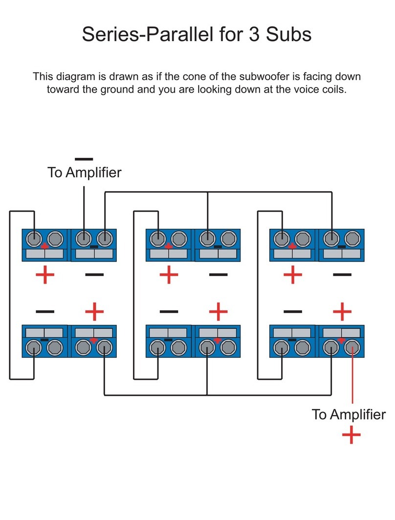
AudioBahn 3 SUB SERIES-PARALLEL - DIAGRAM User manual