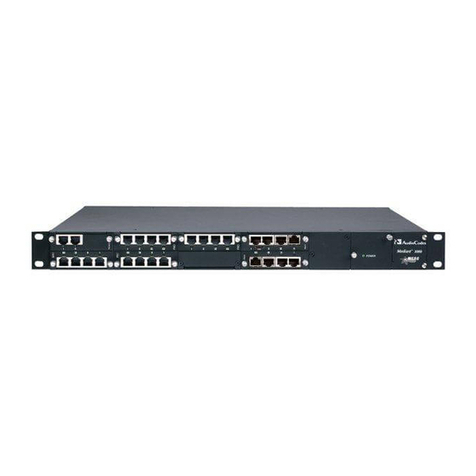
AudioCodes Mediant 3000 Series Assembly instructions

Document #: LTRT-94701 May 2008
Hardware Installation Manual
Version 5.4


Version 5.4 3 May 2008
SIP Hardware Installation Manual Contents
Table of Contents
1Introduction .........................................................................................................9
2Physical Description.........................................................................................11
2.1 Components...........................................................................................................11
2.2 Chassis ..................................................................................................................14
2.2.1 Dimensions ..............................................................................................................14
2.2.2 Card Cage and Slot Assignment .............................................................................14
2.2.3 Alarm LEDs and ACO Button ..................................................................................18
2.3 6310 Blade.............................................................................................................19
2.3.1 LEDs ........................................................................................................................21
2.3.2 Reset Button and Restoring Defaults ......................................................................23
2.3.3 RS-232 Interface Port ..............................................................................................23
2.3.4 RTM-6310 Rear Transition Module .........................................................................24
2.3.5 RTM-6310 Redundancy Rear Transition Module....................................................26
2.4 8410 Blade.............................................................................................................27
2.4.1 LEDs ........................................................................................................................29
2.4.2 LED Array Display ...................................................................................................30
2.4.3 RTM-8410 Rear Transition Module .........................................................................32
2.5 SA/M3K Alarm and Status Blade ...........................................................................34
2.6 Chassis Cooling System ........................................................................................36
2.7 Power Supply ......................................................................................................... 38
2.7.1 Power Entry Module (PEM/DC/3K) .........................................................................39
2.7.2 Power Supply Modules (PS/DC/3K) ........................................................................41
3Installation .........................................................................................................43
3.1 Unpacking and Checking Package Contents.........................................................43
3.2 Mounting ................................................................................................................43
3.3 Cabling...................................................................................................................45
3.3.1 Earthing (Grounding) the Chassis ...........................................................................45
3.3.2 Cabling RTM-6310 Interfaces..................................................................................46
3.3.2.1 Connecting STM-1/OC-3 PSTN Interfaces ............................................. 46
3.3.2.2 Connecting T3 PSTN Interfaces ............................................................. 47
3.3.2.3 Connecting GbE Interfaces to IP Network .............................................. 48
3.3.3 Cabling RTM-8410 Interfaces..................................................................................50
3.3.3.1 Connecting E1/T1 PSTN Interfaces ........................................................ 50
3.3.3.2 Connecting Ethernet Interfaces to OAMP and Control IP Networks....... 54
3.3.3.3 Connecting GbE Interfaces to IP Network .............................................. 55
3.3.4 Connecting the Alarm Terminal Block Closures ......................................................56
3.3.5 Connecting the RS-232 Port to a PC.......................................................................58
3.3.6 Connecting Power ...................................................................................................58
4Maintenance and Repair ...................................................................................61
4.1 Ensuring ESD Protection .......................................................................................61
4.2 Replacing Blades/RTMs.........................................................................................62
4.2.1 Removing Blades/RTMs ..........................................................................................62
4.2.2 Inserting Blades/RTMs ............................................................................................64
4.3 Replacing the Power Supply Module ..................................................................... 64
4.4 Replacing the Power Entry Module........................................................................ 65
4.5 Replacing the Fan Tray Module ............................................................................. 66

SIP Hardware Installation Manual 4 Document #: LTRT-94701
3000 Series Gateways & Media Servers
4.6 Replacing the Air Filter...........................................................................................66
4.7 Replacing 155-Mbps Optical SFP Transceiver Modules (Only 6310 Blades)........68

Version 5.4 5 May 2008
SIP Hardware Installation Manual Contents
List of Figures
Figure 2-1: Front Panel Main Components ............................................................................................12
Figure 2-2: Rear Panel Main Components.............................................................................................13
Figure 2-3: Fully Populated Chassis with 6310 Blades..........................................................................16
Figure 2-4: Front/Rear Panels of High Availability with 8410 Blade ......................................................17
Figure 2-5: Fan Tray Unit with Alarm LEDs and ACO Button ................................................................18
Figure 2-6: 6310 Blade ...........................................................................................................................19
Figure 2-7: Components Location on 6310 Blade..................................................................................20
Figure 2-8: RTM-6310 Ports Location ....................................................................................................25
Figure 2-9: RTM-6310 Redundant Rear Transition Module...................................................................26
Figure 2-10: 8410 Blade .........................................................................................................................27
Figure 2-11: 8410 Blade Component Description ..................................................................................28
Figure 2-12: LED Array Display on 8410 VoP Blade .............................................................................31
Figure 2-13: RTM-8410 for Mediant 3000 (42 Spans - Two SCSI Ports) and IPmedia 3000................33
Figure 2-14: RTM-8410 for 16 Spans (Single SCSI Port) - Only for Mediant 3000 ...............................34
Figure 2-15: SA/M3K Blade LEDs Location ...........................................................................................35
Figure 2-16: Fan Tray Module................................................................................................................37
Figure 2-17: Air Baffle Panel for Unoccupied Front-Panel Slots............................................................37
Figure 2-18: Power Entry Module (PEM) used with 8410 Blades..........................................................39
Figure 2-19: Power Entry Module (PEM) used with 6310 Blades..........................................................39
Figure 2-20: PS/DC/3K Power Supply Module ......................................................................................41
Figure 3-1: Chassis Mounted in 19-inch Rack .......................................................................................44
Figure 3-2: Cabling the PSTN Fiber Optic Interface ..............................................................................47
Figure 3-3: Mini SMB-to-BNC Adaptor Cable (Separate Customer Order) ...........................................48
Figure 3-4: Cabling the SMB Connector Pair for T3 Interface ...............................................................48
Figure 3-5: RJ-45 LAN Ethernet Network Port and Connector ..............................................................49
Figure 3-6: Cabling for LAN Redundancy in Mediant 3000 HA System Only ........................................49
Figure 3-7: 100-Pin SCSI Patch Cable Adapter for 16 Spans (Not Supplied) .......................................51
Figure 3-8: 100-Pin SCSI Female Connector on RTM-8410 Blade .......................................................52
Figure 3-9: 68-Pin SCSI Female Connector on RTM-8410 Blade .........................................................53
Figure 3-10: Cabling PEM Ethernet Ports to Control and OAMP Networks ..........................................54
Figure 3-11: RJ-45 Connector Pinouts...................................................................................................55
Figure 3-12: RJ-45 LAN Ethernet Network Port and Connector ............................................................56
Figure 3-13: Spring-Cage Alarm Terminal Block Pins ...........................................................................57
Figure 3-14: Normal Logic Alarm Connection (Redundancy Scheme) ..................................................57
Figure 3-15: RS-232 Cable Adapter (Supplied) .....................................................................................58
Figure 3-16: Power Feed Cable Terminated with Crimp-Connection Type DC Terminal Block ............59
Figure 3-17: DC Power Connector with and without Screw-type Terminal Block Connector ................60
Figure 4-1: Removing / Inserting Front-Panel Blade using Ejector / Injector Latches ...........................62
Figure 4-2: Blank Panel for Unoccupied Slots........................................................................................63
Figure 4-3: Removing the Air Filter ........................................................................................................67
Figure 4-4: Air Filter................................................................................................................................67
Figure 4-5: Inserting Protective Dust Cover into SFP Cage...................................................................68
Figure 4-6: Unlocking the SFP Module ..................................................................................................69
Figure 4-7: Inserting SFP Module into the Blade's SFP Cage ...............................................................69

SIP Hardware Installation Manual 6 Document #: LTRT-94701
3000 Series Gateways & Media Servers
List of Tables
Table 2-1: Number of Communication Blades/RTMs per Device ..........................................................11
Table 2-2: 3000 Series Front Panel Component Descriptions...............................................................12
Table 2-3: 3000 Series Rear Panel Component Descriptions ...............................................................13
Table 2-4: Chassis Dimensions.............................................................................................................14
Table 2-5: Blade/RTM Assignment per Chassis Slot Number ...............................................................15
Table 2-6: Chassis Front-Panel Alarm LEDs Description ......................................................................18
Table 2-7: Blade Status LEDs Description .............................................................................................21
Table 2-8: Gigabit Ethernet (GBE) LEDs Description ............................................................................21
Table 2-9: PSTN LEDs (STM-1/OC-3 or T3 Interface) Description .......................................................22
Table 2-10: cPCI LEDs...........................................................................................................................22
Table 2-11: RTM-6310 Ports Description...............................................................................................24
Table 2-12: Blade Status LEDs Description...........................................................................................29
Table 2-13: Ethernet LEDs Description..................................................................................................29
Table 2-14: PSTN E1/T1/J1 LEDs Description (Applicable Only to Mediant 3000/TP-8410)................30
Table 2-15: cPCI LEDs...........................................................................................................................30
Table 2-16: RTM-8410 Ports Description...............................................................................................32
Table 2-17: SA/M3K Blade LEDs Description........................................................................................36
Table 2-18: DC Power Supply Specifications.........................................................................................38
Table 2-19: PEM Front View Component Descriptions..........................................................................40
Table 2-20: PS LEDs Description...........................................................................................................41
Table 3-1: RJ-45 Connector Pinouts for Gigabit Ethernet Interface ......................................................49
Table 3-2: Trunk Numbers for 68- and 100-Pin SCSI Connectors Per Supported Span Configuration 50
Table 3-3: Recommended Cable Terminations for 68-Pin and 100-Pin SCSI Connectors ...................51
Table 3-4: E1/T1 Connections 1 - 25 on the 100-Pin SCSI Connector..................................................52
Table 3-5: E1/T1 Connections 26 - 42 on the 68-pin SCSI Connector ..................................................53
Table 3-6: RJ-45 Connector Pinouts ......................................................................................................56
Table 3-7: Alarm Terminal Block Pin Details..........................................................................................57

Version 5.4 7 May 2008
SIP Hardware Installation Manual Notices
Notice
This document describes the physical description and hardware installation of AudioCodes
3000 product family series of gateways and media servers: Mediant 3000 media gateway, TP-
8410 cPCI blade, and TP-6310 cPCI blade; IPmedia 3000 media server, IPM-8410 cPCI
blade, and IPM-6310 cPCI blade.
Information contained in this document is believed to be accurate and reliable at the time of
printing. However, due to ongoing product improvements and revisions, AudioCodes cannot
guarantee accuracy of printed material after the Date Published nor can it accept responsibility
for errors or omissions. Updates to this document and other documents can be viewed by
registered Technical Support customers at http://www.audiocodes.com, under Support /
Product Documentation.
© Copyright 2008 AudioCodes Ltd. All rights reserved.
This document is subject to change without notice.
Date Published: May-06-2008 Date Printed: May-07-2008
Tip: When viewing this manual on CD, Web site or on any other electronic copy,
all cross-references are hyperlinked. Click on the page or section numbers
(shown in blue) to reach the individual cross-referenced item directly. To
return back to the point from where you accessed the cross-reference, press
the ALT and Åkeys
Trademarks
AudioCodes, AC, Ardito, AudioCoded, NetCoder, TrunkPack, VoicePacketizer, MediaPack,
Stretto, Mediant, VoIPerfect and IPmedia, OSN, Open Solutions Network, What's Inside
Matters, Your Gateway To VoIP, 3GX and Nuera, Netrake, InTouch, CTI² and CTI Squared
are trademarks or registered trademarks of AudioCodes Limited. All other products or
trademarks are property of their respective owners.
WEEE EU Directive
Pursuant to the WEEE EU Directive, electronic and electrical waste must not be disposed
of with unsorted waste. Please contact your local recycling authority for disposal of this
product.
Customer Support
Customer technical support and service are provided by AudioCodes’ Distributors,
Partners, and Resellers from whom the product was purchased. For Customer support for
products purchased directly from AudioCodes, contact support@audiocodes.com.
Abbreviations and Terminology
Each abbreviation, unless widely used, is spelled out in full when first used. Only industry-
standard terms are used throughout this manual. Hexadecimal notation is indicated by 0x
preceding the number.

SIP Hardware Installation Manual 8 Document #: LTRT-94701
3000 Series Gateways & Media Servers
Related Documentation
Document # Manual Name
LTRT-897xx (where xx represents
the document version)
Mediant 3000, TP-8410 and TP-6310 SIP User's Manual
LTRT-898xx IPmedia 3000, IPM-8410 and IPM-6310 SIP User's Manual
LTRT-690xx Mediant 3000, Mediant 2000 and TP Series SIP Release Notes
LTRT-590xx IPmedia Series and IPM Series SIP Release Notes
LTRT-523xx Product Reference Manual
Caution Electrical Shock
The equipment must only be installed or serviced by qualified service
personnel.
Note: Throughout this manual, and unless otherwise specified, the term device
refers to the Mediant 3000 media gateway and IPmedia 3000 media server
systems.
Note: Throughout this manual, and unless otherwise specified, the term blade refers
to TP-8410, IPM-8410, IPM-6310, and TP-6310 cPCI blades.

Version 5.4 9 May 2008
SIP Hardware Installation Manual 1. Introduction
1 Introduction
This document provides a hardware description of AudioCodes 3000 Family Series VoIP
Media Gateways and Media Servers as well as step-by-step instructions on installing these
devices. Installation instructions include mounting, cabling, and hardware maintenance.
The 3000 Family Series includes the following products:
Media Gateway:
•Mediant 3000 media gateway
•TP-8410 compactPCI™ (cPCI) blade
•TP-6310 cPCI blade
Media Server:
•IPmedia 3000 media server
•IPM-8410 cPCI blade
•IPM-6310 cPCI blade
As the products of the 3000 Family Series are similar in hardware and installation, the
following generic terms are used to represent them throughout this document:
Device: refers to the Mediant 3000 and IPmedia 3000 systems
8410 blade: refers to the TP-8410 and IPM-8410 cPCI blades
6310 blade: refers to the TP-6310 and IPM-6310 cPCI blades
However, wherever differences exist, the full product name is mentioned.

SIP Hardware Installation Manual 10 Document #: LTRT-94701
3000 Series Gateways & Media Servers
Reader's Notes

Version 5.4 11 May 2008
SIP Hardware Installation Manual 2. Physical Description
2 Physical Description
This section provides a physical description of the device.
2.1 Components
The device includes the following components:
A 19-inch, 2U high rack-mount chassis (refer to ''Chassis'' on page 14).
Hot-swappable communication blades and rear transition modules (RTM), as listed in
the table below:
Table 2-1: Number of Communication Blades/RTMs per Device
Number of cPCI Blades
6310 Series
8410 Series
System
Mode
SA/M3K
6310 RTM-6310 RTM-6310
Redundant
8410 RTM-8410
Simplex 1 1 1 -- 1
2 for 42-84 spans
1 for 16 spans
Mediant
3000
HA 2 2 1 1 2 2
IPmedia
3000
Simplex 1 1 1 -- 1 1
Notes:
•The device either implements the 6310 (refer to ''6310 Blade'' on page
19) or 8410 (refer to ''8410 Blade'' on page 27) blade series.
•RTM refers to Rear Transition Module.
•HA refers to 1+1 High Availability mode, supported only by Mediant 3000
(i.e., not IPmedia 3000).
•HA for 16-spans 8410 blade configuration will be supported in the next
applicable release.
•The blades are housed in the chassis' front-panel slots; the RTMs are
housed in the chassis' rear-panel slots. For the blades' slot assignment in
the chassis, refer to ''Card Cage and Slot Assignment'' on page 14.
•The Alarm and Status blades (SA/M3K) are housed in the chassis' front-
panel slots (refer to ''SA/M3K Alarm and Status Blade'' on page 34).

SIP Hardware Installation Manual 12 Document #: LTRT-94701
3000 Series Gateways & Media Servers
Modules:
•Two Power Supply modules (PS/DC/3K) located on the right side of the front
panel (refer to PS/DC/3K Power Supply Modules).
•One Fan Tray module (FM/M3K) located on the left side of the front panel (refer
to ''Chassis Cooling System'' on page 36).
•One Air Filter (AF/3K) located within the Fan Tray unit (refer to ''Chassis Cooling
System'' on page 36).
•Two Power Entry Modules (PEM/DC/3K) located on the left side of the rear panel
(refer to Power Entry Module (PEM/DC/3K)).
ID Prom component for defining hardware versions of the various modules.
DIP switch for configuring the shelf’s geographical address.
The main components of the device's front panel are shown below:
Figure 2-1: Front Panel Main Components
Table 2-2: 3000 Series Front Panel Component Descriptions
Item # Component Description
1 Electrostatic discharge (ESD) terminal.
2 Fan Tray module (housing Air Filter), with system alarm LEDs, ACO button, and
component location diagram indicating numbering of blade slots and Power Supply units.
3 Latches and screws for securing modules/blades to chassis.
4 Power Supply units (two for load sharing).
5 Power Supply LEDs.
6 Integral mounting brackets for mounting in a standard 19-inch Telco rack.
7 Blade slots (currently covered with blank panels) for housing communication blades (6310
or 8410 series blades, and SA/M3K Alarm and Status blades).

Version 5.4 13 May 2008
SIP Hardware Installation Manual 2. Physical Description
The main components of the device's rear panel are shown below:
Figure 2-2: Rear Panel Main Components
Table 2-3: 3000 Series Rear Panel Component Descriptions
Item # Component Description
1 Two Power Entry Modules (PEM).
2 Latches and screws to secure blades and modules to chassis.
3 Blade slots (currently covered with blank panels) for housing the rear transition modules
(RTM), which provide the I/O interfaces.
4 ESD terminal lug.
7 Earthing terminal (one-hole G-32 lug and 6-8 AWG wire).
Note: A diagram indicating the numbers of blade slots and Power Supply units is
located on the Fan Tray panel (above the ESD and earthing terminals).

SIP Hardware Installation Manual 14 Document #: LTRT-94701
3000 Series Gateways & Media Servers
2.2 Chassis
The device's chassis is comprised of a compact, rugged 19-inch rack mount unit, 2U high
(3.5" or 89 mm), designed to meet NEBS Level 3 requirements. The device is a four-slot
chassis (four front and four rear slots) for housing the cPCI blades, and Alarm and Status
blades. The front and rear blades interface via a midplane located in the middle of the
chassis. The device's modular design allows easy installment and replacement of modules
such as the Fan Tray and Power Entry modules.
The chassis includes an ID Prom component that clearly defines the hardware version. The
chassis also includes a DIP switch for configuring the shelf geographical addressing.
2.2.1 Dimensions
The device's chassis dimensions are listed in the table below.
Table 2-4: Chassis Dimensions
Dimension Value
Width 48.3 cm (19 inches)
Height 2U or 8.9 cm (3.5 inches)
Depth 29.68 cm (11.69 inch)
Weight (fully loaded) 13 kg (29 lb)
Weight (fully loaded in packaging) Approx. 16 kg (35.5 lb)
2.2.2 Card Cage and Slot Assignment
The chassis contains four front and rear card slot cages. Blades and RTMs are inserted
from the front and the back and engage the midplane on either side, inside the card cage.
A diagram indicating the number of the slots and Power Supply unit is located on the Fan
Tray panel (refer to ''Chassis Cooling System'' on page 36). The midplane contains slot
keys (located in the middle of the midplane), which match the appropriate blade/RTM. This
prevents insertion of a blade/RTM in an incorrect slot.
Notes:
•While the slot keys on the midplane are designed to prevent the insertion
of a blade in an incorrect location, ensure that you don’t force a
blade/RTM into a slot to avoid damaging either the blade/RTM or the
midplane.
•High Availability (HA) is applicable only to Mediant 3000 (i.e., not
supported for IPmedia 3000 systems).
•All unoccupied slots are covered with protective blank panels (refer to
''Replacing Blades'' on page 62).
•The default IP addresses of the 8410 and 6310 blades depends on the
slot in which they reside: Slot #1 is 11.3.9.1 (active blade); Slot #3 is
11.3.9.2 (redundant blade). The subnet address for both blades is
255.255.255.252.

Version 5.4 15 May 2008
SIP Hardware Installation Manual 2. Physical Description
The blade/RTM slot assignment in the chassis is described in the table below.
Table 2-5: Blade/RTM Assignment per Chassis Slot Number
Implemented BladeChassis
Panel
Slot #
6310 Blade Series 8410 Blade Series
1 6310 blade.
This is the active blade when device
configured for HA.
8410 blade.
This is the active blade when device
configured for HA.
2 Alarm and Status blade (SA/M3K).
This is the active blade when device
configured for HA.
Alarm and Status blade (SA/M3K).
This is the active blade when device
configured for HA and operates with the
VoP blade in Slot #1.
3 Standby (redundant) 6310 blade
when device configured for HA. For
Simplex configuration, this slot is
covered by a blank panel.
Standby (redundant) 8410 blade when
device configured for HA. For Simplex
configuration, this slot is covered by a
blank panel.
Front
4 Standby (redundant) Alarm and
Status blade (SA/M3K) when device
configured for HA. For Simplex
configuration, this slot is covered by
a blank panel.
Standby (redundant) Alarm and Status
blade (SA/M3K) when device configured
for HA and operates with the VoP blade in
Slot #3. For Simplex configuration, this slot
is covered by a blank panel.
1 Not used - covered by a blank panel. Not used - covered by a blank panel.
2 Rear transition module (RTM-6310)
supporting:
STM-1/OC-3 or T3 interfaces
(SW configurable using
PSTNTransmissionType ini file
parameter - refer to the device's
User's Manual).
GbE interfaces.
Rear transition module (RTM-8410),
providing:
Single SCSI connector for 16 PSTN
E1/T1 spans, or two SCSI connectors
for 1-42 spans.
(Note: The SCSI connectors are
applicable only to Mediant 3000).
Two RJ-45 ports for GbE interfaces.
Note: For IPmedia 3000, the RTM-8410
with two SCSI ports (not used) is
implemented.
3 RTM-6310 Redundancy when device
configured for HA. For Simplex
configuration, this slot is covered by
a blank panel.
Not used - covered by a blank panel.
Rear
4 Not used - covered by a blank panel. RTM-8410 providing:
Two SCSI connectors for E1/T1 spans
43-84.
Two RJ-45 connectors for GbE
interface.
Notes
This RTM is applicable only to Mediant
3000.
This RTM is also present when device
supports only 1-42 spans.
For 16 spans, this slot is covered by a
blank panel.

SIP Hardware Installation Manual 16 Document #: LTRT-94701
3000 Series Gateways & Media Servers
The figures below show the chassis slot assignment when implementing the 6310 or 8410 blade
series:
Device Implementing 6310 Blade Series:
Figure 2-3: Fully Populated Chassis with 6310 Blades
Legend:
1. Front Panel: 6310 blade (active blade for Mediant 3000 HA configuration) in Slot
1.
2. Front Panel: Alarm and Status blade (active blade for Mediant 3000 HA
configuration) in Slot 2.
3. Front Panel: Standby (redundant) 6310 blade in Slot 3 (applicable only to
Mediant 3000 HA configuration). In a Simplex configuration, this slot is covered
with a blank panel.
4. Front Panel: Standby (redundant) Alarm and Status blade in Slot 4 (applicable
only to Mediant 3000 HA configuration). In a Simplex configuration, this slot is
covered with a blank panel.
5. Blank panels covering unoccupied slots.
6. Rear Panel: RTM-6310 in Slot 2, providing PSTN STM-1/OC-3 or T3 interfaces,
and dual Gigabit Ethernet (GbE) interfaces.
7. Rear Panel: RTM-6310 Redundant in Slot 3 (applicable only to Mediant 3000
HA configuration), providing dual GbE interface. In a Simplex configuration, this
slot is covered with a blank panel.

Version 5.4 17 May 2008
SIP Hardware Installation Manual 2. Physical Description
Device Implementing 8410 Blade Series:
Figure 2-4: Front/Rear Panels of High Availability with 8410 Blade
Legend:
1. Front Panel: 8410 blade (active blade for Mediant 3000 HA configuration) in Slot
1.
2. Front Panel: Alarm and Status blade (active blade for Mediant 3000 HA
configuration) in Slot 2.
3. Front Panel: Standby (redundant) 8410 blade in Slot 3 (applicable only to
Mediant 3000 HA configuration). In a Simplex configuration, this slot is covered
with a blank panel.
4. Front Panel: Standby (redundant) Alarm and Status blade in Slot 4 (applicable
only to Mediant 3000 HA configuration). In the Simplex configuration, this slot
is covered with a blank panel.
5. Rear Panel: Blank panels covering unoccupied slots.
6. Rear Panel: RTM-8410 in Slot 2, providing:
♦PSTN E1/T1 (Trunks 1 to 42, or 1 to 16) interfaces - refer to note below
(applicable only to Mediant 3000).
♦Dual Gigabit Ethernet interfaces.
7. Rear Panel: RTM blade (RTM-8410) in Slot 4 (applicable only to Mediant
3000), providing PSTN E1/T1 (Trunks 43 to 84) interfaces and Gigabit Ethernet
interfaces.

SIP Hardware Installation Manual 18 Document #: LTRT-94701
3000 Series Gateways & Media Servers
2.2.3 Alarm LEDs and ACO Button
Fault detection severity alarm LEDs and an Alarm Cut-Off (ACO) button are located on the
Fan Tray module (refer to the figure below), which is housed in the chassis' front panel.
Figure 2-5: Fan Tray Unit with Alarm LEDs and ACO Button
The ACO button is used to mute the external Telco alarm relay devices attached to the
Power Entry Module (refer to ''Power Entry Module (PEM/DC/3K)'' on page 38). When the
ACO button is activated (by being pressed), all alarm relays are returned to normal
position, de-activating the alarm relay devices. The chassis LEDs and other device alarm
signals are not affected.
The fault detection alarm LEDs (described in the table below) are connected to the Alarm
and Status blade.
Table 2-6: Chassis Front-Panel Alarm LEDs Description
LED Color Status Description
Green On Normal operation.
SYSTEM
Red On System failure.
Green On No Critical alarms.
CRITICAL
Red On (Default when device powered on) Detection of a fault(s)
categorized as “Critical” (i.e., Critical alarm). When this LED
is on, the MAJOR and MINOR LEDs are also lit.
Green On No Major alarms.
MAJOR
Orange On (Default when device powered on) Detection of a fault(s)
categorized as “Major” (i.e., Major alarm). When this LED is
on, the MINOR LED is also lit.
Green On No Minor alarms.
MINOR
Orange On (Default when device powered on) Detection of a fault(s)
categorized as "Minor" (i.e., Minor alarm).

Version 5.4 19 May 2008
SIP Hardware Installation Manual 2. Physical Description
LED Color Status Description
Green On Initialization completed successfully (i.e., normal functioning
of the chassis hardware).
SHELF
Red On (Default when device powered on) Undergoing initialization
(or failure of the chassis hardware).
2.3 6310 Blade
The 6310 blade is a member of AudioCodes’ 6310 series TrunkPack cPCI VoP
communication platform. The blade is a high-density, hot-swappable, cPCI resource blade
(form factor 6U PICMG 2.16) with a capacity of up to 2,016 DS0 channels, supporting all
necessary functions for voice, data, and fax streaming over IP networks. The blade is
considered a complete gateway / media server module. The blade occupies one slot of a
cPCI chassis, and features its own MAC and IP address. In addition, the blade provides
automatic protection switching (APS) capability (1+1) for STM-1/OC-3 PSTN interfaces.
The blade is housed in the chassis' front-panel slot, providing an RS-232 port, a reset
button, and various LEDs.
Figure 2-6: 6310 Blade
The blade is supplied with a rear input/output (I/O) module referred to as the Rear
Transition Module (RTM). The RTM-6310 provides the I/O connections to the supported
interfaces: IP, and one STM-1/OC-3 or three T3 PSTN interfaces. For a detailed
description of the RTM-6310, refer to ''RTM-6310 Rear Transition Module'' on page 24.
For Mediant 3000 systems, the blade is designed for protection capabilities. The redundant
RTM (RTM-6310 Redundant), housed in the rear panel, provides 6310 blade redundancy
protection by routing all calls between the active blade (previously redundant) and the
RTM. The RTM-6310 Redundant itself does not provide any PSTN ports. For a detailed
description of the RTM-6310 Redundant, refer to ''RTM-6310 Redundancy Rear Transition
Module'' on page 26.
Notes:
•PSTN APS is partially compliant to GR-253 only.
•The 6310 blade supports either STM-1/OC-3 or T3 PSTN interface,
depending on software configuration (using the PSTNTransmissionType
ini file parameter).
•HA (i.e., blade protection) is applicable only to Mediant 3000 systems.

SIP Hardware Installation Manual 20 Document #: LTRT-94701
3000 Series Gateways & Media Servers
The following figure displays the location of the blade's LEDs (refer to ''LEDs'' on page 21),
Reset button (''Reset Button and Restoring Defaults'' on page 22), and RS-232 port (refer
to ''RS-232 Interface Port'' on page 23).
Figure 2-7: Components Location on 6310 Blade
This manual suits for next models
5
Table of contents
Other AudioCodes Server manuals
Popular Server manuals by other brands
Dell
Dell PowerConnect W-AirWave 7.6 Configuration guide

HP
HP T5125 - Compaq Thin Client Administrator's guide

Sun Microsystems
Sun Microsystems Fire F6800 Quick reference guide
Dell
Dell External OEMR R910 Technical guide
AMX
AMX MAX-MDL200M MULTI DISC LOADER instruction manual
Brandywine
Brandywine ENTA-2 user guide
