Audiodesign Crunch CR1000CAP User manual

CR 1000CAP
POWER CAPACITOR .1 FARAD
BEDIENUNGSANLEITUN*
OWNER,S MANUAL
VERS. 1.2

2
Seite
3
4
5
5
6
7
8
8
1.0 Farad
12 ~ 16V DC
18V DC max.
–20 ~ + 60° C
285 x ø76 mm
Einbauzubehör
BEDIENUNGSANLEITUNG
Inhaltsverzeichnis
Verwendungsmöglichkeiten
Sicherheitshinweise
Montage
Erstes Aufladen
Anschlussbeispiele
Funktionsbeschreibung
Entladen
Justierung der Voltanzeige
TECHNISCHE DATEN
Nenn-Kapazität:
Dauer-Betriebsspannung:
Maximale Betriebsspannung:
Betriebstemperatur:
Abmessungen (ohne Montagehalter):
LIEFERUMFANG
1 Pufferkondensator
2 Montagehalter
1 Lade-/Entlade-Widerstand
1 Bedienungsanleitung

3
VERWENDUNGSMoGLICHKEITEN
Der Pufferkondensator wird in Kraftfahrzeugen zur Stabilisierung und
Unterstützung der Stromversorgung eines Verstärkers eingesetzt, wenn dieser
schnell und für kurze Zeit hohe Ströme benötigt. Er kann kurzfristige Belastungen
der Bordspannungen bei z.B. besonders tiefen, kräftigen Bässen ausgleichen.
Durch die Verwendung des Pufferkondensators ergibt sich eine wesentlich
bessere Leistungsentfaltung des Verstärkers.
Car Audio Verstärker benötigen für den optimalen Betrieb hohe Stromstärken.
Herkömmliche Fahrzeugbatterien sind normalerweise nicht für die zusätzliche
Versorgung eines Verstärkers ausgelegt.
Ein weiterer Vorteil des Pufferkondensators ist das Filtern von Wechsel-
spannungen, die im Netzteil des Verstärkers indiziert werden. Ungefilterte
Wechselspannungen können hörbare Interferenzen verursachen.
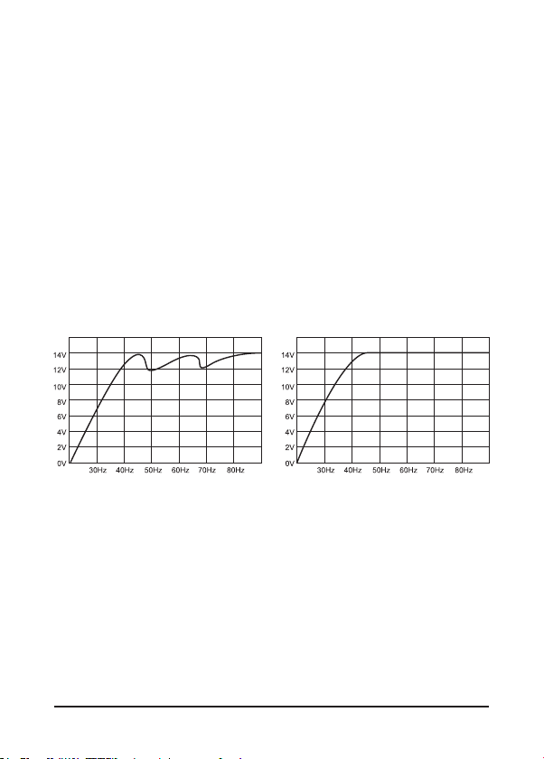
Bassleistung bei 50Hz und 70Hz
ohne Pufferkondensator
Bassleistung bei 50Hz und 70Hz
mit Pufferkondensator
..
4
SICHERHEITSHINWEISE
Bevor Sie mit der Installation des Kondensators beginnen, sollten Sie die
folgenden Anweisungen der Bedienungsanleitung genau befolgen!
Andernfalls besteht Verletzungsgefahr oder das Gerät könnte ernsthaft
beschädigt werden.
Der Pufferkondensator entspricht der KFZ-Richtlinie für den Betrieb in Fahrzeugen
innerhalb der Europäischen Union und besitzt eine E-Zertifizierung als auch
eine CE-Kennzeichnung (Konformitätserklärung).
Der Anschluss des Pufferkondensators an das 12 V-Bordnetz darf nur durch
qualifiziertes Fachpersonal erfolgen. Dabei ist besondere Sorgfalt geboten. Bei
Kurzschlüssen können gefährlich hohe Ströme fließen.
Der Pufferkondensator speichert sehr hohe Stromreserven und könnte bei
falscher Handhabung sogar explodieren. Wird der Kondensator zweckentfremdet,
nicht richtig angeschlossen oder nicht fachgerecht repariert, können Sach- oder
Personenschäden daraus resultieren.
Der Kondensator muss fest und fachgerecht an einer mechanisch stabilen Stelle
montiert werden.
Auf keinen Fall darf der Pufferkondensator mit einer höheren Spannung als
18 Volt betrieben werden oder ein Kurzschluss an den Strom-Anschlussklemmen
verursacht werden.
Schützen Sie den Kondensator vor Feuchtigkeit und Hitze (zulässiger
Einsatztemperaturbereich -20 °C bis +60 °C).
Für die Reinigung nur ein weiches, trockenes Tuch verwenden, auf keinen Fall
Chemikalien oder Wasser.
VORSICHT
ELEKTROSCHOCK

5
MONTAGE
Für bestmögliche Ergebnisse sollte der Kondensator so nahe wie möglich
bei der Endstufe installiert werden. Die Kabel zwischen dem Kondensator
und der Endstufe sollten möglichst kurz sein und einen möglichst großen
Querschnitt aufweisen. Die Kabel sind so zu verlegen, dass deren Isolierung
während des Einbaus und des Betriebes nicht beschädigt werden.
1.) Verwenden Sie die beiliegenden Halter, um den Kondensator an einer
mechanisch stabilen Stelle fest anzuschrauben. Montieren Sie das Gerät
keinesfalls auf stark vibrierenden Flächen wie beispielsweise einem
Gehäusesubwoofer.
2.) Der korrekte Anschluss ist auf der nächsten Seite dargestellt. Zur
Vermeidung von Störgeräuschen sollte der Masseanschluss des Kondensator
an der gleichen Stelle erfolgen, an der auch der Verstärker angeschlossen
wird.
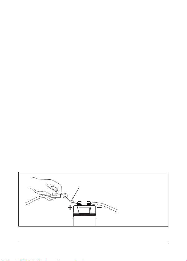
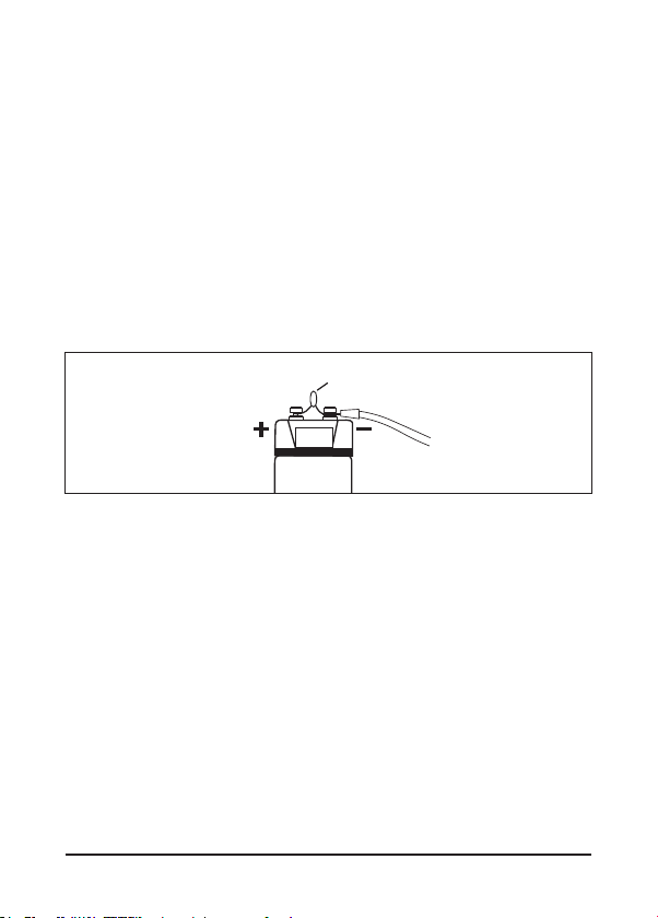
ERSTES AUFLADEN
Beim erstmaligen Aufladen des Kondensators sollte unbedingt der
beiliegende Lade-Widerstand benutzt werden, um den Ladestrom zu
begrenzen und Anschlussfunken zu vermeiden. Verbinden Sie dabei das
Massekabel „-” mit dem „-” Anschluss des Kondensators. Dann klemmen Sie
den beigelegten Widerstand an den „+“ Anschluss des Kondensators und
halten das „+“ Kabel des Batterieanschlusses bzw. des Verteilerblocks an
das andere Ende der Lampe.
Der Widerstand kann nach ca. einer Minute oder wenn der Kondensator ca.
10 Volt erreicht hat entfernt werden. Schließen Sie nun das „+“ Kabel der
Batterie an den „+“ Anschluss des Kondensators an, um den Ladevorgang
bis zu 12~14V abzuschließen.
ACHTUNG: Währendes des Ladeprozesses zwischen 5 ~ 10 Volt blinkt
das Display. Der Widerstand könnte während des Ladens sehr heiß
werden. Vermeiden Sie einen Kurzschluss an zwischen den
Anschlüssen.
Batterie-
anschluss
Masse-
anschluss
Widerstand
10.00

Verstärker
6
AN SCHLUSSBEISPIELE
Anschluss mit Verteilerblock (empfohlen)
Sicherung
Anschluss ohne Verteilerblock
Sicherung
Hinweis:
Achten Sie auf korrekte Polung!
Verteilerblock
Batt.
Hinweis:
Achten Sie auf korrekte Polung!
Verstärker
Batt.

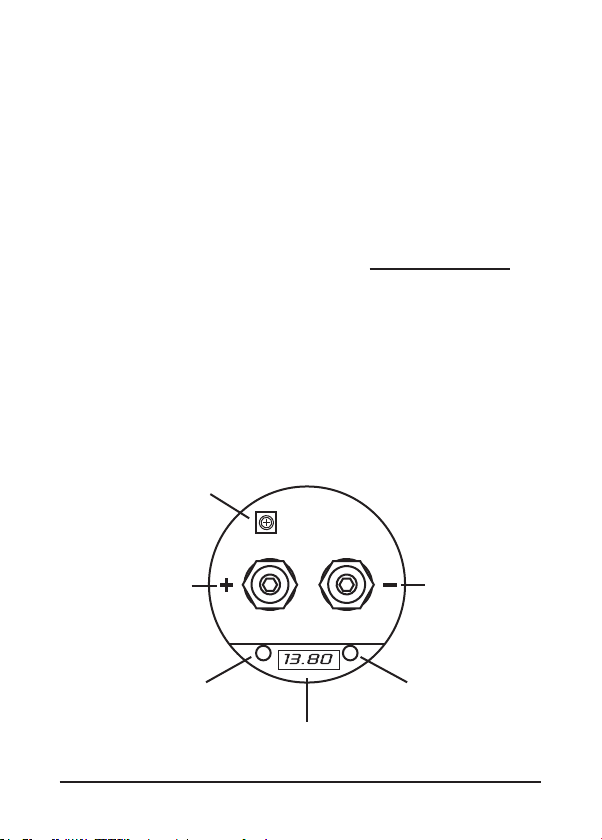
FUNKTIONSBESCHREIBUNG
Digital Voltanzeige
Diese Anzeige zeigt die aktuelle Betriebsspannung in Volt an und ist somit
eines der wichtigsten Features zur Statusanzeige der Stromversorgung des
Fahrzeuges.
Während des Aufladens (5 ~ 10 Volt) oder wenn die anliegende Spannung
unter 10 Volt fällt, beginnt das Display zu blinken.
Die beiden Status-LEDs leuchten solbald sich das Display einschaltet und
haben darüber hinaus keine weitere Funktion.
Warnton
Wenn ein Vertauschen der Pole (+ und – Anschluss) vorliegt, ertönt sofort ein
Warnton.
Entfernen Sie in diesem Fall sofort die Anschlüsse. Explosionsgefahr!
Potentiometer
Dieser Regler erlaubt die Justierung der Voltanzeige.Mehr Informationen dazu
auf Seite 8.
Autoremote
Der Kondensator ist mit einer automatischen Aus- und Einschaltfunktion
ausgestattet. Solbald der Kondensator eine Spannungsschwankung bemerkt,
schaltet er sich von selbst ein und schaltet sich wieder von selbst aus, wenn
ca. zwei Minuten keine Schwankung bzw. Aktivität bemerkt wurde.
Potentiometer
Digitale Voltanzeige
Batterie-
anschluss
Masse-
anschluss
7
Status-LEDStatus-LED

8
ENTLADEN
Wenn der Kondensator ausgebaut werden sollte, muss dieser aus Sicher-
heitsgründen komplett entladen werden. Zum Entladen des Kondensators
entfernen Sie das Kabel am „+“ Anschluss des Kondensator. Den „-“
Anschluss lassen Sie noch an Masse angeschlossen. Verbinden Sie dann den
mitgelieferten Entlade-Widerstand mit dem „+“ und „-“ Pol.
Der Entladevorgang kann einige Minuten in Anspruch nehmen.
Es ist empfehlenswert, gegebenenfalls den Widerstand während des
Vorganges mit einer Zange zu halten, da diese sehr heiß werden kann.
Beim Entladen beginnt das Display zu blinken und zeigt ”0.00” an, wenn die
Spannung unter 10 Volt fällt.
ACHTUNG: Entladen Sie den Kondensator niemals ohne den beigelegte
Entlade-Widerstand! Entladen Sie den Kondensator unter keinen
Umständen durch Kurzschließen der Anschlüsse. Der Kondensator
könnte dadurch beschädigt werden oder explodieren.
JUSTIERUNG DER VOLTANZEIGE
Die Justierung der Voltanzeige ist schon ab Werk erfolgt und kann bei Bedarf
nachjustiert werden. Bei der Installation weiterer Kondensatoren können durch
Toleranzen die Anzeigewerte variieren. Dies kann mit dem Potentiometer
nachjustiert werden.
Gehen Sie dabei wie folgt vor:
1.) Messen Sie die aktuelle Betriebsspannung am “+“ und “-“ Pol des Kondensators
mithilfe eines geeigneten Multimeters.
2.) Entfernen Sie dann vorsichtig die Acrylglas-Abdeckung oben am Kondensator
und stellen den Wert am Potentiometer (blaues, eckiges Bauteil) mit einem
geeignetem Schraubendreher auf den Wert, der zuvor gemessen wurde.
3.) Achten Sie unbedingt bei der Demontage darauf, die Anschlussklemmen
nicht kurzzuschließen.
4.) Oder beauftragen Sie Ihren Fachhändler.
Widerstand
10.00
Batterie-
anschluss
Masse-
anschluss

OWNER,S MANUAL
9
Page
10
11
12
12
13
14
15
15
1.0 Farad
12 ~ 16V DC
18V DC max.
–20 ~ + 60° C
285 x ø76 mm
Installation Hardware
Content
Applications
Safety Instructions
Installation
Initial Charging Process
Wiring Diagram
Functional Descriptions
Discharging Process
Voltmeter Adjustment
SPECIFICATIONS
Rated Capacity:
Continuous Voltage:
Maximum Voltage:
Operation temperature:
Dimensions (without Mounting Brackets):
KITINCLUDED
1 Power Capacitor
2 Mounting Brackets (top and bottom)
1 Charging/discharging resistor
1 Owner’s Manual
All specifications are subject to change without notice!
10
APPLICATIONS
The power capacitor is used in vehicles for stabilizing the 12 Volt supply and
support for car audio amplifiers, if fast and temporary high currents are required.
The power capacitor can compensate short-term power peaks on the on-board
electrical system for low and powerful bass operations.
The use of the power capacitors results in a considerably improved power
expansion of the amplifier.
Car audio amplifiers require very high current peaks for a proper operation.
Conventional car battery are not designed to deliver additional power supply
to car audio amplfiers.
Another feature of this power capacitor is to filter car AC voltage included by
the amplifier’s power supply. This can cause audible interferences in the audio
signal.
Bassperformanze at 50Hz and 70Hz
without capacitor
Bassperformanze at 50Hz and 70Hz
with capacitor
11
SAFETY INSTRUCTIONS
Before you begin with the installation, please attend the following advices
in this manual. Otherwise the risk of injury or a damage of the device
consists.
The power capacitor is equivalent to common directives to be operated in
vehicles inside the European Union and owns a E-mark certification also as a
CE-mark.
The capacitor should be installed by qualified and skilled personnel only. Special
carefulness is essential, because in case of short circuits hazardous high currents
could occur.
The power capacitor stores an extremly large amount of electricity and may
explode or cause serious injury. If the device is used for other purposes than
originally intented or if not proper used or installed, personal injury or material
damage could occur.
The capacitor should be mounted at a mechanically stable position in the vehicle.
The device should be fixed properly and professional.
At no time the power capacitor should be exposed to voltages higher than
specified (max. 18 Volts) or its terminals shorted directly.
Protect the capacitor against humidity and heat (admissable temperature range
- 20 °C to +60 °C).
For cleaning use a dry and soft cleaning tissue, by no means any chemicals
or water.
WARNING!
ELECTRICAL
HAZARD
12
INSTALLATION
For achieving the best results the capacitor should be located close-by the
amplifier. The cables between capacitor and amplifier should be short as possible
and should have large cross section. While installing the cables or the operation,
ensure not to damage the insulation of the cables.
1.) Tightly screw the device with the supplied brackets and screws as close as
possible to the amplifier on a machanically stable position. By no means install
the capacitor on any kind of speaker enclosure or on high vibrating positions.
2.) The correct wiring is displayed on the next page. To avoid any interferences,
connect the capacitor’s ground connection at the same ground terminal like the
amplifier.
INITIAL CHARGING PROCESS
For the first initial charging use by any means the supplied light bulb, to limit
the charge current and to avoid connecting sparks. Connect the ”–” ground wire
with the ”–” terminal of the capacitor.
Then clamp the supplied light bulb to the ”+” terminal of the capacitor and hold
the ”+” wire of the battery or distribution block at the other end of the light bulb.
The light bulb can be disconnected after approx. one minute or if the capacitor
reached a load of 10 volts. Then connect the “+” terminal of the battery with the
“+” terminal of the capacitor to complete the charging process until 12~14 volts
are achieved.
During the charging process (5 ~ 10 Volt) the display starts flashing!
The light bulb may get very hot during the charging process.
Please avoid any short circuit on the terminals.
Battery
Terminal
Ground
Terminal
Resistor
10.00

13
WIRING DI AGRAM
Wiring with Distribution Block (recommended)
Wiring without Distribution Block
Batt.
Amplifier
Amplifier
Fuse
Fuse
Note:
Ensure correct polarity!
DIstribution
Block
Batt.
Note:
Ensure correct polarity!
14
FUNCTIONAL DESCRIPTIONS
Digital Voltmeter
This display indicates the actual operating voltage and is one of the most
important features to display the status of the car’s power supply.
During the charging process (5 ~ 10 Volts) or if the voltage drops below
10 Volts, the display starts flashing.
The both Status-LEDs start to glow as soon as the display is on, beyond that
they have no other function.
Audio Warning
If a interchange of the poles is occured, an audio warning is hearable.
In this case all disconnect all connections directly. Danger of Explosion!
Potentiometer
This controller allows to adjust the voltmeter.
Attend the information on Page 15.
Autoremote
The powercap is equipped with an autoremote function. If the powercap detects
any fluctation of the connected voltage, it turns automatically on. The powercap
turns off after approx. two minutes, when no fluctation or activity is detected.
Potentiometer
Digital Voltmeter
Battery
terminal
Ground
terminal
Status-LEDStatus-LED
15
DISCHARGING PROCESS
If the capacior will be de-installated you need to discharge it completely. To
discharge the capacitor, remove the wire at the ”+” terminal of the capacitor.
Keep the ground terminal “-” connected. Then bridgeover the ”-”pole and
”+”pole of the capacitor with the supplied resistor.
The discharging process could last some minutes.
It is recommended to use a gripper during this procedure, because the resistor
may get very hot.
The display is flashing and shows ”0.00” during the discharging when the
voltage drops below 10 Volts. If the light bulb stops flashing, the discharging
process is accomplished.
CAUTION: Never discharge the capacitor without the supplied resistor.
Never discharge the capacitor with bypassing the terminals (short
circuit).The capacitor may get damaged or explode.
VOLTMETER ADJUSTMENT
The adjustment is already done by the factory, but can be redone if necessary.
By using additional capacitors, various indicated values could be occured. This
can be adjusted by the potentiometer.
Follow these instructions:
1.) Measure the actual operating voltage on the ”+” und ”–”pole of the capacitor
by using an appropriate multimeter.
2.) Remove the acrylic-cover of the capacitor and adjust the value with the
potetiometer (little blue box) by using a appropriate screwdriver to the same
value, you have measured before.
3.) Ensure while removing the cover, not to short the terminals.
4.) Or assign your car audio retailer.
Resistor
10.00
Battery
Terminal
Ground
Terminal

Audio Design GmbH
Am Breilingsweg 3 · D-76709 Kronau/Germany
Tel. +49 7253 - 9465-0 · Fax +49 7253 - 946510
www.crunchaudio.de · www.audiodesign.de
© Audio Design GmbH, all rights reserved.
Technical changes, errors and mistakes reserved.
Table of contents
Languages:
Other Audiodesign Automobile Accessories manuals

Popular Automobile Accessories manuals by other brands


Mazda
Mazda CX-3 quick start guide

Offroad Animal
Offroad Animal RB-JWR-JK-07-ASM0 Fitting instructions

Dakota Digital
Dakota Digital LED Tail Lights for 1972 Impal LAT-NR181 installation instructions

Synergy
Synergy PPM-5802 manual

DV8 OFFROAD
DV8 OFFROAD RRJK-03 installation manual

Steinhof
Steinhof H-238 FITTING AND OPERATION MANUAL