Audion Elektro LAMINO 301 LM User manual
AUDION ELEKTRO®
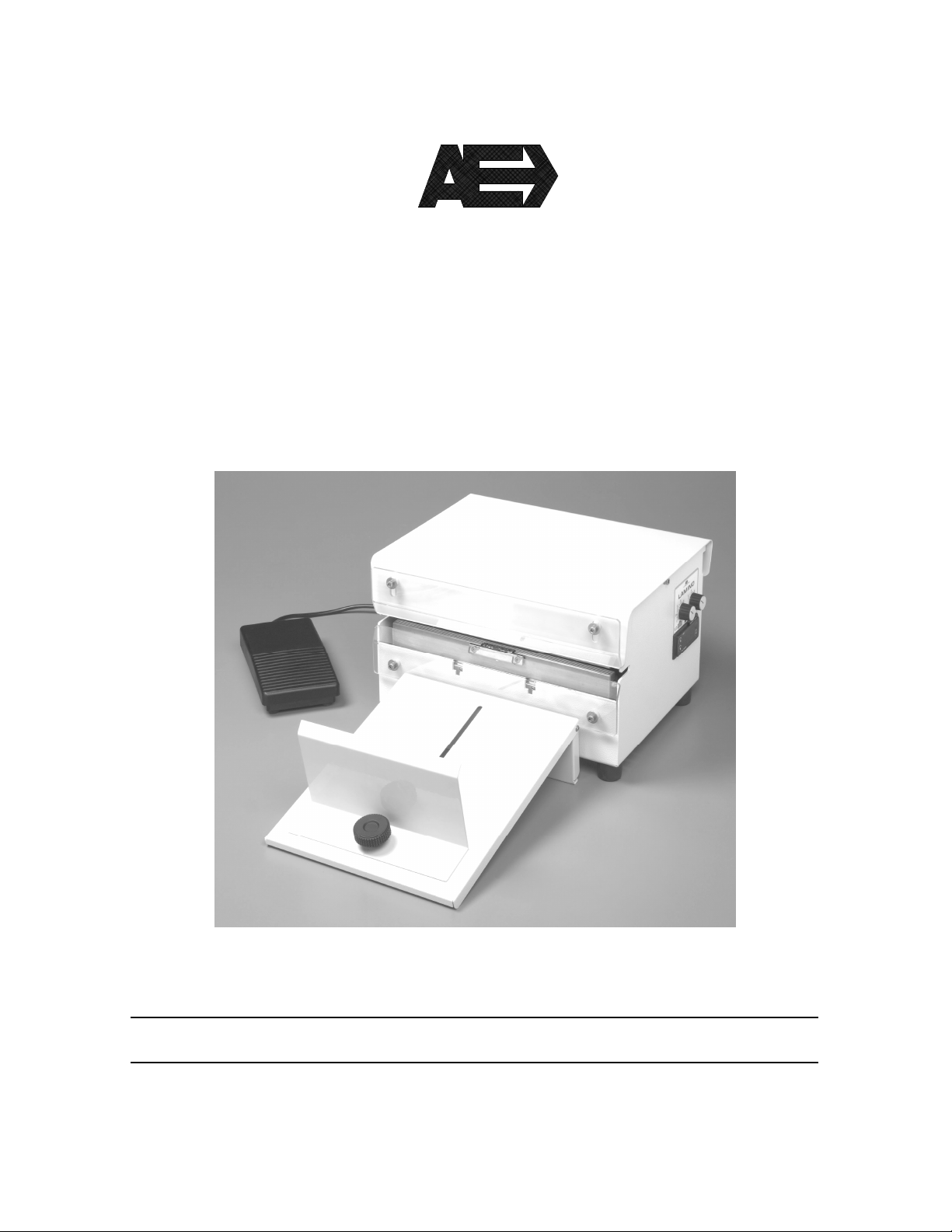
LAMINO
301 LM
MANUAL
LAMINO 301 LM ENG. Rev.03

2
All rights reserved. Nothing from this edition is allowed to be copied and/or made public by means of print, photo copy or any other
way without previous written permission of AUDION ELEKTRO.
AUDION ELEKTRO reserves the right to change spare parts and/or specifications without previous notice. Contents of this manual
can also be changed without previous warning.
AUDION ELEKTRO cannot be hold responsible for eventual damage caused by specifications deviating from the standard model.
Although extreme care has been exercised during writing this manual, AUDION ELEKTRO will not accept any liability for eventual
errors in this manual and/or for the consequences of (mis)interpretation of the contents.
AUDION ELEKTRO is not responsible for damage or problems which result from the use of other than the original spare parts.
If this manual has not been supplied with instructions for certain repairs, adjustments and maintenance, you should contact your
dealer of AUDION ELEKTRO.

3
CONTENTS
1General information ............................................................................................................................ 6
1.1 Use and safekeeping of the instructions manual...................................................................... 6
1.2 Expected use ............................................................................................................................ 6
1.3 Technical characteristics .......................................................................................................... 7
1.3.1 Lamino 301..................................................................................................................... 7
1.4 Moving and transport................................................................................................................ 7
1.5 Safety rules............................................................................................................................... 8
2Instructions for use.............................................................................................................................. 9
2.1 Installation................................................................................................................................. 9
2.2 Electrical wiring......................................................................................................................... 9
2.3 Switching on the machine....................................................................................................... 10
2.4 First employ ............................................................................................................................ 11
2.5 Switching off the machine....................................................................................................... 11
2.6 Emergency stop...................................................................................................................... 12
2.7 Seal with code embossing...................................................................................................... 12
2.7.1 Code composition......................................................................................................... 12
3Control panel..................................................................................................................................... 14
3.1 Cycle time setting ................................................................................................................... 14
3.1.1 Symbols........................................................................................................................ 14
3.1.2 Operative cycle time setting ......................................................................................... 14
3.2 Sealing temperature setting.................................................................................................... 15
3.2.1 Keys symbols ............................................................................................................... 15
3.2.2 sealing temperature setting.......................................................................................... 15
3.2.3 Set temperature visualization....................................................................................... 15
3.2.4 Errors warning list (heating control) ............................................................................. 16
3.2.5 alarm message list ....................................................................................................... 16
3.3 Automatic mode...................................................................................................................... 17
4Maintenance ..................................................................................................................................... 18
4.1 Cover machine opening.......................................................................................................... 18
4.1.1 Cover............................................................................................................................ 18
4.1.2 Front protection ............................................................................................................ 18
4.2 Main preventive maintenance rules........................................................................................ 18
4.2.1 Sealing jaws ................................................................................................................. 18
4.3 Thermoelectric protections ..................................................................................................... 19
4.3.1 Thermal protection by thermofuse ............................................................................... 19
4.3.2 Thermal protection by probe ........................................................................................ 19
4.4 Line fuses replacement .......................................................................................................... 19
4.5 Temperature jaws probe replacement.................................................................................... 20
4.5.1 Probe access................................................................................................................ 20
4.5.2 Replacement ................................................................................................................ 20
4.6 Heating elements replacement............................................................................................... 21
4.6.1 Heating elements access ............................................................................................. 21
4.6.2 Heating elements replacement .................................................................................... 21
4.6.3 Thermoregulator calibration ......................................................................................... 22
5Recommended spare parts .............................................................................................................. 24
6Electrical diagram ............................................................................................................................. 25
7Problems & solutions ........................................................................................................................ 26
7.1 Electric circuit.......................................................................................................................... 26
7.2 Sealing.................................................................................................................................... 26

4
7.3 Alarm messages ..................................................................................................................... 26
8Discard the machine ......................................................................................................................... 27
9Conditions of guarantee.................................................................................................................... 27
9.1 Liability.................................................................................................................................... 27
9.2 Guarantee............................................................................................................................... 27

5
SYMBOLS
Warning meaning danger
Warning meaning particular suggestion
Warning meaning suggested maintenance
pict. a
2
1
3
4
Table of contents


