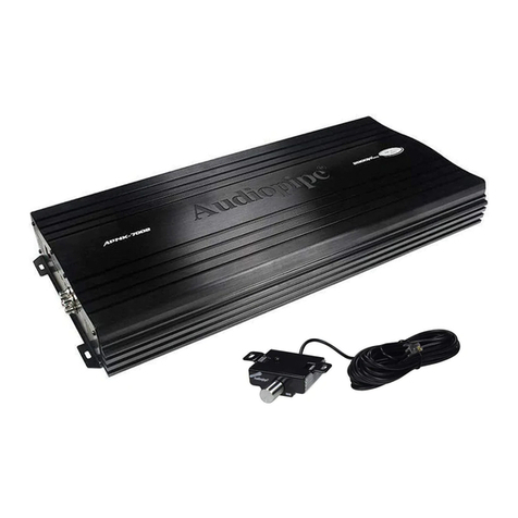
Audiopipe APMR-2002 User manual

- 1 -
EnglishEnglish

- 1 -
English
The Audiopipe APMR-2002 is a full-featured four-channel marine amplifier incorporating
the following features:
Specially coated circuit boards, that resist mold, mildew and moisture damage.
•Pulse-Width Modulated (PWM) MOSFET power supply for maximum performance with
minimal distortion.
•
Remote turn-on with "soft start" muting to prevent turn-on "thump".
•Advanced circuitry design featuring bridgeable and mixed mode operation for use in
various system configurations including 4, 3, or 2 channel systems.
•
Variable high-pass/low-pass electronic crossover with a 12dB per octave slope (adjustable
range: 55Hz to 5.5kHz).
•
Variable bass boost circuit to reinforce low frequency signals that may be lost due to
subwoofer enclosure design.
•
Adjustable input level controls with ground loop isolation to minimize noise and distortion.
•2 Ohm stereo stable, 4 Ohm mono stable.
•Platinum-plated power, speaker, and RCA connectors.
•Speaker level input.
•
•Low profile construction with aluminum heat sink for efficient heat dissipation.
Description .....................................................................................................................
Input Connections and Audio Controls ...........................................................................
Connections for Power and Speakers ............................................................................
Installation ......................................................................................................................
Mounting Precautions ....................................................................................................
Wiring Precautions .........................................................................................................
Wiring and Applications ..................................................................................................
Setting the Gain ..............................................................................................................
Setting the Crossover .....................................................................................................
Setting the Bass Boost ...................................................................................................
Final System Check .......................................................................................................
Troubleshooting .............................................................................................................
Product Specifications .............................................................................................
1
1
2
4
4
4
5
8
8
8
8
9
10
This manual describes the basic requirements to install the Audiopie APMR-2002 marine
amplifier. The installation of this marine amplifier can be quite complex to install, if you
do not possess the necessary knowledge and tools to perform this installation, please
contact your local Audiopipe dealer.

5. Frequency Range Multiplier
6. CH1 / CH2 Filter
7. Output Mode Selector Switch
8. Speaker Level Input
9. Remote
- 1 -
English
The APMR-2002 uses an unregulated MOSFET power supply for superior sound and
output wattage. In addition, a torpid-coil is used to transfer power with minimal performance
loss due to heat. To avoid unwanted noise, a double-sided conformal printed circuit board
with strategically placed components keeps AM RFI subdued.
All of the connections and controls for the APMR-2002 are conveniently located at the
ends of the marine amplifier and labeled appropriately. To ensure the best possible electrical
connections, the power, speaker, and RCA inputs are platinum-plated. An additional benefit
of this marine amplifier is the ability to create a 2, 3, or 4 channel amplified system with
a flip of a switch (see Application section). In the event of component failure or a short
circuit, the APMR-2002 incorporates safe guards and an outboard ATC fuse to prevent
damage to the marine amplifier.
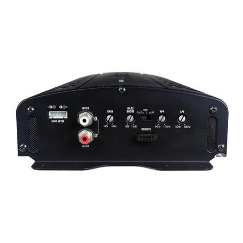
The front panel of the APMR-2002 contains both connections for RCA and speaker level
inputs, along with the audio controls as shown below.
Figure 1
Gain Controls
This allows you to set the nominal operating level of the marine amplifier. The marine
amplifier's range, 250mV to 2.5V for RCA inputs or 500mV to 5V for speaker level inputs,
can accommodate input levels from virtually any brand of source unit.
Bass Boost Control
The marine amplifier also features a “high-Q” (i.e. narrow frequency band) Bass Boost circuit.
It acts much like an equalizer, with adjustable gain (from 0 to ~18dB) fixed at 45Hz. Use
this feature to tune low-frequency audio response to compensate for a less than ideal
subwoofer enclosure design. The added boost produces rich, full bass tones that are
normally difficult to reproduce in the car audio environment.
NOTE: If Bass Boost is undesired, set Bass Boost to 0dB.
1. CH1 / CH2 RCA Input
2. Gain Control
3. Bass Extender
4. CH1 / CH2 Frequency (Hz)

- 2 -
English
WARNING: When using the speaker (high-level) inputs, the Black wire must be grounded
at the Radio. Failure to do this will result in noise and improper operation.
The rear panel of the APMR-2002 contains power and speaker connections as shown
below.
Figure 2
High-pass/Low-pass Filter Controls
Frequency (Hz) Selection Control
The crossover frequency is fully adjustable between 55Hz and 5500Hz (via the Crossover
Frequency Multiplier) for a wide range of crossover points. Use this feature, along with
your speaker manufacturer's recommended crossover frequencies, to quickly design a
more advanced system (see Applications on page 4) NOTE: If the X-Over Mode Switch
is set to OFF, varying the Freq (Hz) Control will produce no effect.
Crossover Frequency Multiplier Switch
When engaged, this switch increases the crossover frequency by a factor of 10. Example:
If the Freq (Hz) dial is set for 240 Hz, pushing in the Multiplier Switch changes the setting
to 2400 Hz.
X-Over Mode Switch
This switch is equipped with a 12dB per octave electronic filter for precise frequency
attenuation with minimal phase distortion. The steep crossover slope keeps midrange
tones out of the subwoofer and thereby eliminates an unnatural "nasal" tone quality in the
audio system. A filter is activated by sliding the X-Over Mode Switch to either LP or HP.
Input Mode Switch
This switch allows you to set the input mode. Stereo input allows full left and right stereo
operation. Right (bridged) input allows single channel input for bridged operation. This is
especially useful in high-powered systems when using one marine amplifier for each
subwoofer/speaker. L + R (sum mono) allows a stereo input to be summed into a mono
output.
Speaker Level Inputs
These provide connections for a high-level stereo source. In addition, these connections
are provided for installations when the source unit’s RCA outputs are unavailable.
1 42 3 5 6
1. CH1 Speaker Output
2. CH2 Speaker Output
3. Ground
4. Remote Turn-on
5. Battery
6. 35 Amp Fuse

- 3 -
English
Figure 3
Connections for power and speakers

English
This section suggests Mounting and Wiring Precautions for installing the Audiopipe
APMR-2002 marine amplifier. If you do not posses the necessary tools and installation
experience, do not attempt to install this marine amplifier. Instead, contact your local
Audiopipe dealer to perform the installation.
- 4 -
Read all of the wiring precautions prior to making any connections. If you are unsure and/or
don't have the necessary installation hardware, contact your local Audiopipe dealer to
perform the installation.
1.
2.
3.
4.
5.
6.
7.
8.
9.
Before you begin the installation, make sure the source unit Power switch is in the OFF
position.
Disconnect the negative (–) lead of the battery (or batteries) before making any power
connections.
When making connections, be sure that each connection is clean and secure. Insulate
final connections with electrical tape or shrink tubing. Failure to do so may damage your
equipment.
A good ground is critical for the performance of the marine amplifier. A ground wire
should be run directly from the battery to the marine amplifier. Use black insulated 10-
gauge or larger wire for the marine amplifier's ground (–) power lead.
Add an additional fuse holder and fuse at the positive (+) terminal of the battery. The
fuse rating should equal the total current consumption at full output of the marine
amplifier(s). Use red insulated 10-gauge or larger wire for the marine amplifier's positive
(+) power lead. Do not install the fuse until the complete installation has been performed.
When replacing the marine amplifier's fuse, always use one having the same amperage
rating. Substituting a higher rated fuse or a slow-blow type can result in serious damage
to the marine amplifier.
When creating passage holes for power cables, RCA's cords, and speaker wires, use
grommets to eliminate any sharp edges created during drilling. This will protect the wire
from being nicked and causing a short circuit.
Extra cable can cause signal loss and act as an "antenna" for noise. Use only high-
quality RCA cords that are no longer than necessary.
In multiple marine amplifier systems, it is recommended to use a relay on the remote
turn-on lead of the radio.
Prior to mounting the marine amplifier, make sure it is safe to mount the marine amplifier
in that location. Failure to do so can result in serious damage to the boat. In addition,
stainless steel hardware should be used to mount the marine amplifier and additional
accessories. When possible, use a nut and bolt with a lock washer to secure the marine
amplifier. Extra care and attention is necessary in marine installations due to the uncertainty
of water conditions.
Additional precautions and suggestions:
1.
2.
3.
4.
For the most efficient cooling, mount the marine amplifier so cool air runs along the
length of the heat sink, rather than across them. To increase air movement and circulation,
a cooling fan can be installed.
Mount the marine amplifier on a rigid surface; avoid mounting to subwoofer enclosures
or areas prone to vibration.
Prior to drilling and holes, make sure the proposed mounting holes will not cut into the
fuel tank, fuel lines, electrical wiring, or through the boat.
Do not mount the marine amplifier where it is susceptible to water.
Bridged - Mono Subwoofer System
- 5 -
English
The Audiopipe APMR-2002 2-channel marine amplifier can be used in a variety of system
applications. Here are some examples to help plan your own installation.
Figure 4
In this application the marine amplifier is bridged for mono operation to drive a subwoofer.

Figure 5
In this application, the marine amplifier is used in stereo and drives two full-range (or satellite
or subwoofer) speakers. NOTE: A passive crossover must be used with satellite speakers.
2-Channel Full-Range, Satellite, or Subwoofer Stereo System
(Set INPUT SELECT Switch to STEREO)
- 6 -
English

Mixed-Mode Satellite and Subwoofer System
(Set INPUT SELECT Switch to STEREO)
- 7 -
English
Figure 6
The marine amplifier can be configured for a mixed-mode operation. The table provides
component values to create a 6dB per octave crossover at specified frequencies. Use
components that have a +5% tolerance and capacitors rated at 100V.
NOTE: Choose the same frequency for both LP and HP crossovers. Do not overlap
frequencies, as this may damage the marine amplifier.
NOTE: Chart values based on 4 Ohm speakers.
C (uF)
497
398
318
265
199
FREQ (Hz)
80
100
125
150
200
L (mH)
8.0
6.4
5.1
4.2
3.2

Start the engine and turn on the source unit. After a two-second delay, slowly increase
the Volume Control and listen to the audio. If you hear any noise, static, distortion or
no sound at all, check the connections, and also refer to Troubleshooting. Depending
on your system design, the levels may become quite loud even at low Volume Control
settings. Until you get an "audio feel" of the system's power, use care when adjusting
controls.
Turn the Balance Controls to their extreme positions and listen to the results. Audio
imaging should match control settings (audio from the left speaker when balance is left).
Increase the volume and verify that the marine amplifier reproduces audio (at full
frequencies) without distortion. If you hear distortion, check the connections and verify
that the Gain Control is set correctly. Another possibility is damaged speakers or under-
powered speakers. Once again refer to Troubleshooting for additional help.
- 8 -
EnglishEnglish
After completing the installation, follow these steps to set the Gain Control and then perform
the Final System Checks.
1.
2.
3.
4.
Turn the Gain Control all the way counter-clockwise.
Turn the vessel's Ignition Switch to the ON position. Then turn the ON/OFF Switch on
the source units to the ON position. Set all Tone or Equalization Controls to "flat" positions
and turn Loudness off.
Play a CD or Tape and set the Volume Control at 75% of full level. NOTE: If the system
uses an equalizer, set its frequency controls to “flat” positions.
Slowly increase the Gain Control. Stop when you hear a slight distortion of audio.
1.
2.
3.
1.
2.
3.
Initially set the Bass Boost control to its full left position (i.e. 0dB).
Listen to a variety of music styles (e.g. Rock, Rap, etc.) and slowly increase the Bass
Boost control until a noticeable increase in low bass response is perceived.
Slowly adjust the Bass Boost control (up or down) to realize the best bass response.
CAUTION: If you hear a “pop” (due to speaker over-excursion), lower the Bass Boost to
prevent speaker damage. If the system sounds muddy and distorted (due to marine
amplifier clipping), lower Bass Boost to avoid shutdown from overheating.
The Audiopipe AP2002 features a fully adjustable crossover. To set the crossover, follow
these steps.
1.
2.
Using the X-Over Mode Switch, select the desired mode - LP for Low Pass, HP for High
Pass and OFF for Full Range.
Using the Freq (Hz) Control, select the desired frequency. If the desired frequency
exceeds the range of the Freq (Hz) Control, press the Crossover Frequency Multiplier
Switch to increase the value by a multiplier of 10.
• For example, 55Hz x 10 = 550Hz or 550Hz x 10 = 5.5kHz.

•
- 9 -
English
Low or no remote turn-on voltage. Check remote connections at marine amplifier and
source unit.
Blown marine amplifier fuse. Replace with new fast-blow fuse (same rating).
Power wires not connected. Check battery and ground wiring at marine amplifier; also
check battery connections.
Speaker leads shorted. Check speaker continuity to ground, it should not show a
common ground.
Speakers not connected or are blown. Check speaker connections at marine amplifier,
measure coil impedance.
•
•
•
•
•
Thermal protection circuits are shutting marine amplifier off. Check location for adequate
ventilation; consult an authorized Audiopipe Dealer.
Gain is not set properly, or damaged speaker cones. Review Setting Gain; inspect
each speaker cone for signs of damage. (i.e. frozen cone, burning smell, etc.)
Incorrect wiring or short circuit. Review Installation and check all wiring connections.
•
•
•
Speakers wired incorrectly, which causes cancellation of bass frequencies. Check
polarity of wires from marine amplifier to each speaker as defined by the system
design.
Marine amplifier is picking up alternator noise or radiated noise. Turn down input gain;
move audio cables away from power wires. Check power and ground connections on
marine amplifier; install an in-line noise filter on source unit’s power wire; check
alternator and/or voltage regulator; test for weak battery or add water to battery.
•

- 10 -
English
20Hz ~ 20kHz
>100dB
.05% all channels driven
250mV ~ 2.5V
500mV ~ 5V
400W (200W x 2)
200W (100W x 2) @ .05% THD
125W x 2 @ .5% THD
300W x 1 @ .5% THD
(H)55 x (W)176 x (L)260 mm
28A @ 382 Watts
Frequency Response ........................................................
Signal Noise Ratio .............................................................
THD ...................................................................................
Input Sensitivity Low Level ................................................
Input Sensitivity Speaker Level .........................................
Maximum Power Output ....................................................
Continuous Power Output .................................................
2-Ohm Stereo Output ........................................................
Bridged Power ...................................................................
Dimensions ........................................................................
Current Consumption @ Max Power Output .....................

El amplificador marino Audiopipe APMR-2002 es un equipo de 2 canales que incorpora
las siguientes características:
- 1 -
English
Placa base especialmente revestida, que resiste el polvo, moho y los daños de humedad.
Suministro de energía (PWM) MOSFET para máximo rendimiento con mínima distorción.
Encendido remoto con “suave comienzo” para prevenir encendidos con “ruidos sordos”.
•
•
•
•Diseños de circuitos avanzados caracterizando módulos de operación mezclados y en
puente para uso en variados sistemas de configuración, incluyendo sistemas de 4, 3 ó
2 canales.
Crossover electrónico variable de paso-alto/paso bajo con 12dB por octava (rango
adjustable: 55Hz a 5.5KHz).
•
Circuito variable para el incremento del bajo para reforzar la señal de baja frecuencia
que puede ser perdida debido al diseño encerrado del subwoofer.
•
Controles para ajustar el nivel de entrada con aislamiento a tierra en lazo para minimizar
el ruido y la distorción.
•
Construcción de bajo perfil con desague de aluminio para la disipación eficiente del
calor.
Estéreo estable a 2 Ohms, mono estable a 4 Ohms.
Terminales para potencia, bocinas y RCA en enchape dorado.
Nivel de entrada de las bocinas.
•
•
•
•
Este manual describe los requerimientos básicos para instalar el amplificador marino
Audiopipe APMR-2002. La instalación de este amplificador marino puede ser muy compleja.
Si usted no posee los conocimientos necesarios y las herramientas para realizar esta
instalación, por favor contacte su concesionario Audiopipe local.
Descripcion .....................................................................................................................
Conexiones de entrada y controles de Audio ................................................................
Conexiones para la potencia y las bocinas ....................................................................
Instalación ......................................................................................................................
Precauciones para el montaje ........................................................................................
Precauciones en el alambrado .......................................................................................
Alambrado y aplicaciones ..............................................................................................
Programando la ganancia ..............................................................................................
Programando el crossover .............................................................................................
Programando el incremento del bajo .............................................................................
Verificación final del sistema ..........................................................................................
Solución de problemas ...................................................................................................
Especificaciones del producto ........................................................................................
1
1
2
4
4
4
5
8
8
8
8
9
10

El amplificador marino APMR-2002 utiliza un suministro de energía MOSFET no regulado,
para un sonido superior y salida de voltaje. En adición, una bobina toroidal es usada para
transferir potencia con una pérdida mínima de rendimiento debido al calor. Para evitar
ruidos no deseados, una placa base de doble lado con los componentes estrategicamente
colocados conservando la sintonia del AM RFI en tono suave.
Todas las conexiones y controles estan convenientemente localizadas al final del amplificador
marino y apropiadamente rotulados. Para asegurar las mejores conexiones electricas posibles,
la potencia, las bocinas y las entradas RCA son de enchapes dorados. Un beneficio adicional
de este amplificador marino es la habilidad de crear sistemas amplificados de 2, 3 y 4
canales con un golpe ligero al interruptor (Ver Sección de Aplicación). En el evento de que
un componente falle o haya un corto circuito, el amplificador marino APMR-2002 tiene un
dispositivo de seguridad y un fusible ATC para prevenir daños al amplificador marino.
Controles de Ganancia
Esto le permite el programar el nivel operativo nominal del amplificador marino. El rango
es de 250mV a 2.5V de entrada RCA ó 500mV a 5Vpara el nivel de entrada de las bocinas,
puede acomodar niveles de entrada desde virtualmente cada marca o unidad de suministro.
Control de Incremento del Bajo
El amplificador marino también ofrece un circuito de incremento del bajo “high Q” (ej: una
banda de Frecuencia estrecha).
Esta actua como un ecualizador, con ganancia adjustable (de 0 a –18dB) fijada a 45Hz.
Use esta caracteristica para sintonizar una respuesta de audio de baja Frecuencia para
compensar por un menos que ideal diseño encerrado del subwoofer. El incremento
adicionado produce ricos y completos tonos del bajo que son normalmente dificiles de
reproducir en el ambiente del audio del automóvil.
NOTA: Si el incremento del bajo no es deseado, programe el Incremento del bajo a 0dB.
El panel frontal del amplificador marino APMR-2002 contiene ambas conexiones para RCA
y entrada de nivel a las bocinas, asi como los controles de audio como se muestran debajo.
- 1 -
English
Figura 1
1. Entrada RCA Canal1 / Canal2
2. Control de Ganancia
3. Extensión del Bajo
4. Frecuencias (Hz) Canal1 / Canal2
5. Multiplicador del Rango de Frecuencias
6. Filtro Canal 1 / Canal 2
7. Interruptor del selector del módulo de salida
8. Nivel de Entrada de las bocinas
9. Remoto

- 2 -
English
Figura 2 1 42 3 5 6
Control del filtro de Paso Alto/Paso Bajo
Control de Seleccion de Frecuencia (HZ)
La Frecuencia del crossover esta ajustada totalmente entre 55Hz y 5500Hz (via el multiplicador
de Frecuencia del crossover) por un amplio rango de puntos del crossover. Use esta
característica, conjuntamente con la frecuencia del crossover recomendada por el fabricante
de la bocina, para rápidamente diseñar un sistema mas avanzado (ver Aplicaciones en la
página 4) NOTA: Si el interruptor de módulo del X-over esta colocado en OFF, variando
el control de Frecuencia (Hz) no producirá ningun efecto.
Interruptor del multiplicador de Frecuencia del crossover
Cuando se encaja, este interruptor incrementa la Frecuencia del crossover por el factor 10.
Ejemplo: Si la Frecuencia (Hz) del dial, es programada para 240Hz, empujando el interruptor
multiplicador cambia la programación a 2400 Hz.
Interruptor del Módulo del X-over
Este interruptor está equipado con 12dB por octava del filtro electrónico para precisar la
atenuación de la frecuencia con una fase minima de distorción. La atenuación gradual
del crossover guarda la calidad de los tonos medios fuera del subwoofer y por consiguiente
elimina una calidad de tono “nasal” no natural en el sistema de audio. El filtro es activado
deslizando el interruptor de módulo del X-over hacia LP ó HP.
Interruptor del Módulo de Entrada
Este interruptor le permite programar el módulo de entrada. La entrada estéreo permite una
operación completa estéreo de izquierda y derecha. La entrada derecha (Puente) permite
una entrada de canal simple por operación de puente. Esto es especialmente util en sistemas
de alta potencia cuando es usado un amplificador marino por cada subwoofer/bocina. L +
R ( suma mono) permite una entrada estéreo ser adicionada dentro de una salida mono.
Niveles de Entrada de la Bocina
Estas proveen conexiones para una fuente estéreo de alto nivel. En adición, estas conexiones
se proveen para instalaciones cuando la fuente de salida RCA de la unidad no está habilitada.
PRECAUCION: Cuando se están usando los altos niveles de entrada de las bocinas, el
cable negro debe estar a tierra con el radio. El no hacer esto resultaría en ruidos y una
operación inapropiada.
El panel trasero del amplificador marino APMR-2002 contiene las conexiones de potencia
y de las bocinas como se muestra debajo.
1. Salida de la Bocina Canal 1
2. Salida de la Bocina Canal 2
3. Tierra
4. Encendido del Remoto
5. Batería
6. Fusible de 35 Amp.

Figura 3
Conexiones para la potencia y las bocinas
- 3 -
English

English
- 4 -
Esta sección sugiere precauciones de montaje y cableado para la instalacion del amplificador
marino Audiopipe APMR-2002. Si usted no posee las herramientas y la experiencia
necesaria para la instalación, no trate de instalar este amplificador marino, en vez de
hacerlo, contacte a su concesionario Audiopipe local para hacer la instalación.
Para un enfriamiento mas eficiente, monte el amplificador marino donde el aire frio
circule a lo largo del disipador, en vez de a traves de él. Incrementando el movimiento
y circulación del aire, un ventilador para enfriar puede ser instalado.
Monte el amplificador marino en una superficie rígida; evite montarlo en la protección
del subwoofer o en areas donde exista Vibración.
Antes de barrenar los huecos, asegúrese de que los huecos de montaje no traspasaran
el tanque del fluido, las lineas de fluido, los cables eléctricos.
No monte el amplificador marino donde pueda ser susceptible al agua.
Antes de montar el amplificador marino, asegúrese de que es seguro el montaje del
amplificador marino en esa localización. Si no hace esto, puede resultar en serios daños.
Si es posible, utilice tuerca y tornillo con una arandela para asegurar el amplificador marino.
Precauciones y sugerencias adicionales:
1.
2.
3.
4.
Lea todas las precauciones del alambrado antes de hacer cualquier conexión. Si no esta
seguro y/ó no tiene las herramientas necesarias para la instalación, contacte su concesionario
local Audiopipe para que realice la instalación.
Antes de comenzar la instalación, asegúrese de que el interruptor de potencia de la unidad
está en la posición OFF (apagada).
Desconecte el cable negativo (–) de la batería (ó baterias) antes de hacer cualquier
conexión.
Cuando haga las conexiones, asegúrese de que cada conexión esta limpia y segura,
aisle las conexiones finales con cinta aislante ó tubo encogido. El no hacer esto podria
dañar su equipo.
Una buena conexion a tierra es crítica para el funcionamiento de su amplificador marino.
El cable a tierra debe correr directamente desde la batería al amplificador marino. Use
cable negro aislante calibre 10 o mayor para la tierra del amplificador marino.
Adicione un portafusible adicional y un fusible a la terminal positiva (+) de la batería. El
rango del fusible debe ser igual al consumo total de corriente en una total salida del
amplificador marino. Use cable rojo aislante calibre 10 ó mayor para el cable de potencia
positiva (+) del amplificador marino. No instale el fusible hasta que la una completa
instalación haya sido realizada.
Cuando reemplace el fusible del amplificador marino, siempre use uno que sea del mismo
amperaje. Sustituyendolo por un fusible mayor ó menor puede resultar en serios daños
al amplificador marino.
Cuando este haciendo los huecos para pasar los cables de potencia, los cables RCA, y
los alambres de las bocinas, use arandelas para eliminar cualquier borde cortante mientras
barrena. Esto protegerá los cables de ser dañados y causar un cortocircuito.
Cables extras pueden causar pérdida de señal y actuar como una “antena” para ruido.
Use solamente cables RCA de alta calidad que sean del largo necesario.
En sistemas de múltiples amplificadores marinos, es recomendado usar un rele en el
cable remoto de encendido del radio.
1.
2.
3.
4.
5.
6.
7.
8.
9.

El amplificador marino de 2 canales Audiopipe APMR-2002 puede ser usado en una
variedad de aplicaciones de sistemas. Aqui tenemos algunos ejemplos que les ayudaran
a planificar sus propia instalación.
Figura 4
En esta aplicación el amplificador marino esta en Puente para una operación mono que
maneja el subwoofer. - 5 -
English
Módulo de Puente – Sistema de subwoofer mono

Figura 5
En esta aplicación, el amplificador marino es usado en estéreo y maneja dos bocinas de
rango completo (ó satélite, ó subwoofer).
NOTA: Un crossover pasivo debe ser usado con las bocinas satélites.
- 6 -
English
Sistema Estéreo de 2 canales de satelite, o subwoofer

Sistema de módulo mezclado de satelite y subwoofer
( Seleccione INPUT SELECT cambie a STEREO)
Figura 6:
El amplificador marino puede ser configurado para un módulo de operación mezclada.
La tabla provee valores de componentes para crear un crossover de 6dB por octava en
frecuencias específicas. Use componentes que tengan tolerancia de + de 5% y capacitores
de rango de 100V.
NOTA: Escoja la misma Frecuencia para ambos crossovers el LP y HP. No sobreponga
frecuencias, ya que podria dañar el amplificador marino.
- 7 -
English
NOTA: Los valores de la tabla estan basados en bocinas de 4 ohms.
C (uF)
497
398
318
265
199
FREQ (Hz)
80
100
125
150
200
L (mH)
8.0
6.4
5.1
4.2
3.2
Table of contents
Languages:
Other Audiopipe Amplifier manuals

Audiopipe
Audiopipe APCL-6002 User manual

Audiopipe
Audiopipe APCL-1004 1000W User manual

Audiopipe
Audiopipe APCL-1004 User manual

Audiopipe
Audiopipe APMI-4050 User manual

Audiopipe
Audiopipe APCL-1800ID User manual

Audiopipe
Audiopipe APCL-6002 User manual

Audiopipe
Audiopipe APCL-1800ID User manual

Audiopipe
Audiopipe APMR-1504 User manual

Audiopipe
Audiopipe APMA-2100 User manual

Audiopipe
Audiopipe APNK-7002 User manual