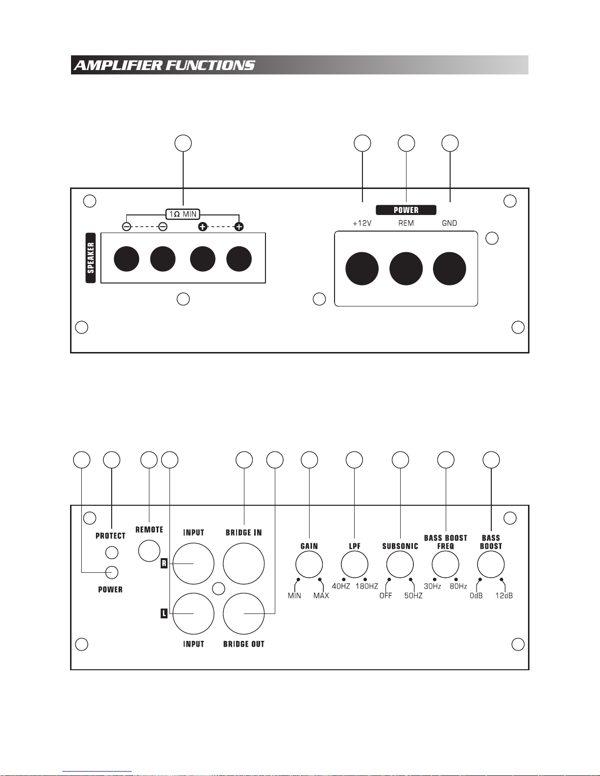
Audiopipe APSM-1300 User manual


21 3 4
APSM-1300/APSM-1500
12
9111056 7 8 1315 14

APSM-2000
21 3 4
129111056 7 8 1315 14

Speaker connection
Never connect the speaker cables with the chassis ground. This may destroy your
amplifier. Check that your speakers are connected correctly which means plus to plus
and minus to minus.
We recommend speaker cable from 2.25 mm to up. The connection ways are shown
in the attachment.
BATT+
Battery + terminal. The +12 Volt power cable must be connected with a fuse in line
near the battery + terminal. Please see the table of cable and fuse selection.
REM
Remote terminal. The remote cable must be connected with the radio remote terminal
so that the amplifier will switch on and off automatically with the radio.
If there are two or more amplifiers installed together, it might be necessary to add an
additional relay. Please consult your dealer.
GND
Chassis ground terminal. The chassis ground cable must be connected very tight on
a nearby massive and electric conductive place.
Gain
Gain control regulates the sensitivity of the amplifier to match the signal output voltage
of your source unit. The gain control is not a volume adjustment. Use high quality CD
music and increase the volume of your source unit to 75% of its minimum volume,
set the gain at the minimum and then increase gain slowly (clockwise). Stop at the
first sign of distortion, then lower the gain a little (counter clockwise) to achieve clear
undistorted music at the maximum level.
Remote Bass Level Control
When using the remote bass level control you can adjust volume in the driver seat.
RCA audio input
These RCA audio inputs connect with your radio RCA outputs. Please use high quality
RCA cables. Keep these cables as short as possible. To avoid electrical disturbances
from your car electronics, route RCA cabloes away from other current carrying cables
in the car. If your radio has only speaker output, you must use a HIGH LOW LEVEL
adaptor.
Bridge in
This RCA jack receives signal from the master amplifier when this amplifier is bridged
as slave. DO NOT use input jacks when the amplifier is working as slave. All the
functions will be adjusted by the master amplifier.
Bridge out
This RCA output sents out bridged signal to another same Class D amplifier in bridging
configuration.
1
2
3
4
5
6
7
8
9

English
Low Pass Filter
Filter out high frequency that the woofer cannot play. Adjust this knob to match the
woofer's frequency response.
SUBSONIC
Filter out unwanted too low frequency. This function will increase the power handing
of your woofer’s. It can adjust the frequency filter from, 10Hz (OFF) to 50Hz.
Bass boost Level
Adjust the boosted frequency from 0 ~ 12dB, APSM-1300/APSM-1500’s boosted
frequency is is adjustable.
Bass boost Frequency
Adjust the boosted center frequency. The frequency can be adjusted from 30Hz to
80Hz, use combine with bass boost level adjusting.
Protect
Protection circuit indicator LED.
Power
Power indicator LED.
15
14
13
12
11
10

We recommend you have the installation done by an Authorized Audiopipe Dealer.
Required power, ground wire and proper external fuse as below:
Fuse
80 AMP
100 AMP
150 AMP
Model
APSM-1300
APSM-1500
APSM-2000
Wire
4 Gauge
2 to 4 Gauge
0 to 2 Gauge
We recommend the fuse should be installed no more than 12 inches from the battery.
The ground wire should be connected directly with the chassis of your vehicle which should
be metal to metal ground point connection. The amplifier must be mounted securely at a
solid, dry and low vibration surface in the trunk or passenger area. Mount the amplifier
in an open air area to insure proper heat dissipation. Mount the amplifier in a place where
can access easily to set the input controllers. Install all amplifier cables as far as possible
from car electrical cables such as the car ignition cable.
IMPORTANT:
When bridging two amplifiers please refer the bridging wiring chart.
•When bridging two amplifiers you should use same model amplifiers.
•Please make sure the negative speaker terminal of two amplifiers are connected by the
same gauge cables as the positive terminal being used.
•
DO NOT connect any signal cables with the input RCA jacks when bridged as slave unit.
•
•The LPF, Input level and remote functions will be disabled on slave amplifier when
bridged.
All the functions of the slave amplifier will be adjusted by the master amplifier.
•

ONE SPEAKER MONO
APSM-1300/APSM-1500

ONE SPEAKER MONO
APSM-2000

TWO SPEAKER MONO
APSM-1300/APSM-1500

TWO AMPLIFIERS LINKED TO ONE CHANNEL
APSM-1300/APSM-1500

TWO AMPLIFIERS LINKED TO ONE CHANNEL
APSM-2000

Check volume control on the radio.
Check GAIN regulator on the amplifier.
Check RCA cables and connections.
Check speaker cables and connections.
Problem
Bass response is low.
Solution
Problem
Run indicator doesn’t light up.
Solution
•
•
•
•
Check all fuses on the amplifier.
Check main fuse near the battery.
Check plus and minus battery cables.
Check remote voltage.
Problem
Run indicator is on but no sound.
Solution
•
•
•
•
One speaker cable could be disconnected the bass.
•
Check chassis ground connection with amplifier cable terminals and battery terminals
connections and check remote turn-on voltage.
Problem
The amplifier switches on and off.
Solution
•
For additional questions please contact your authorized Audiopipe dealer.

RMS @ 4 Ohm (<1% DISTORTION) .......................................
RMS @ 2 Ohm (<1% DISTORTION) .......................................
RMS @ 1 Ohm (<1% DISTORTION) .......................................
Input Level ................................................................................
Frequency Response ...............................................................
LPF ..........................................................................................
SUBSONIC Filter .......................................................................
Bass Boost Frequency .............................................................
Bass Boost Level .....................................................................
THD at 4 Ohm load 30% Rated Power ....................................
Signal Noise Ratio ....................................................................
Best Efficiency .........................................................................
Minimum Load .........................................................................
Optional Remote ......................................................................
Bridgeable with Same Amplifier ...............................................
Overload Protect System .........................................................
Short Circuit Test (max. power) ...............................................
Overheat Protect Temperature ................................................
Components & PCB .................................................................
Transparent Isolation Connector ..............................................
400W
600W
1000W
0.2 ~ 5V
8 ~ 180Hz
40 ~ 180Hz
5 ~ 50Hz
55Hz
0 ~ 12dB
<0.15%
>70dB
>85%
1 Ohm
YES
YES
YES
PASS
80˚C/176˚F
SMT & Double Side Board
YES
APSM-1300
RMS @ 4 Ohm (<1% DISTORTION) .......................................
RMS @ 2 Ohm (<1% DISTORTION) .......................................
RMS @ 1 Ohm (<1% DISTORTION) .......................................
Input Level ................................................................................
Frequency Response ...............................................................
LPF ..........................................................................................
SUBSONIC Filter .......................................................................
Bass Boost Frequency .............................................................
Bass Boost Level .....................................................................
THD at 4 Ohm load 30% Rated Power ....................................
Signal Noise Ratio ....................................................................
Best Efficiency .........................................................................
Minimum Load .........................................................................
Optional Remote ......................................................................
Bridgeable with Same Amplifier ...............................................
Overload Protect System .........................................................
Short Circuit Test (max. power) ...............................................
Overheat Protect Temperature ................................................
Components & PCB .................................................................
Transparent Isolation Connector ..............................................
600W
950W
1500W
0.2 ~ 5V
8 ~ 180Hz
40 ~ 180Hz
5 ~ 50Hz
30 ~ 80Hz
0 ~ 12dB
<0.2%
>70dB
>85%
1 Ohm
YES
YES
YES
PASS
80˚C/176˚F
SMT & Double Side Board
YES
APSM-1500
AUDIOPIPE AMPLIFIERS CAR AMPLIFIERS
Other manuals for APSM-1300
1
This manual suits for next models
2
Table of contents
Other Audiopipe Car Amplifier manuals

Audiopipe
Audiopipe APMI-2075 User manual

Audiopipe
Audiopipe 1600W User manual

Audiopipe
Audiopipe APSM-1150 User manual

Audiopipe
Audiopipe AP-6002 User manual

Audiopipe
Audiopipe AQX-3500.1 User manual

Audiopipe
Audiopipe APCL-1000ID User manual

Audiopipe
Audiopipe APSM-1300 User manual

Audiopipe
Audiopipe 1200W User manual

Audiopipe
Audiopipe APMI-600 User manual

Audiopipe
Audiopipe AQX-2000.I User manual