AUDIOPLUS SMProfessional SVC Series User manual
- Thank you for purchasing the SMProfessional SVC Series Stabilizer.
- To ensure optimum performance and safety, please follow this instruction manual carefully.
- Please retain this manual for future reference.
- For any complaint, feedback or testimonials please contact our distributor / dealer.
1. General
2. Technical characteristics
3. Working principle
4. Operation instruction
SVC Series
Stabilizers
Studiomaster Professional
Automatic Voltage Stabilizer
DIRECT REGULATED
SUPPLY
50
0
100
150
200
250
V
10
0
20
30
A
NORMAL
HIGH VOLTAGE
LOW VOLTAGE
2
SVC series high-accuracy full-automatic AC voltage regulators are our leading products, made up of contact voltage
regulator, servo motor and automatic control circuit. When the voltage of power network in not stable or when the
load changes, the automatic control circuit will sample, amplify and send signal to drive the servo motor to adjust
the position of carbon brush of contact voltage regulator, and enable the output voltage to the rated value, to get
voltage stabilization finally.
The equipment possesses visible advantages such as elegant appearance, compact design, light weight, high
efficiency, no distortion of output waveform, complete protection functions, long service, etc. For sake of the top
quality, the key electronic elements are all imported and performed quality inspection strictly.
The equipment is suitable for areas where power grid fluctuates frequently or changes greatly along the season,
widely applied to industry, scientific research, medical service, school, communication, household appliance, etc,
it can provide any loads with top power supply to ensure the power device can run normally.
The equipment complies with trade standard SB/T10266-1996 (SVC series single - phase 10kVA and below
products.
General
Technical characteristics
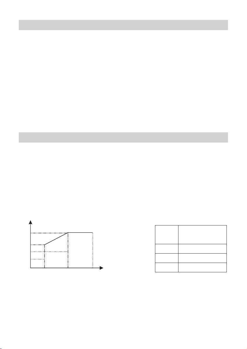
1. Output capability
When mains voltage is lower than 160V, the output capacity of this equipment reduces correspondingly.
2. Overload capability
When input voltage of this equipment changes from 160V to 250V, its overload capability is shown as table 1
under emergency service.
(P---Output capability; Pc----Rated output capability; U----Input voltage)
P/Pc
100%
70%
50%
35%
Output 230V
160 198 250
Diagram 1 Table 1
Overload
ratio
20%
40%
60%
Overload time not
permitted (min)
60
30
5
3
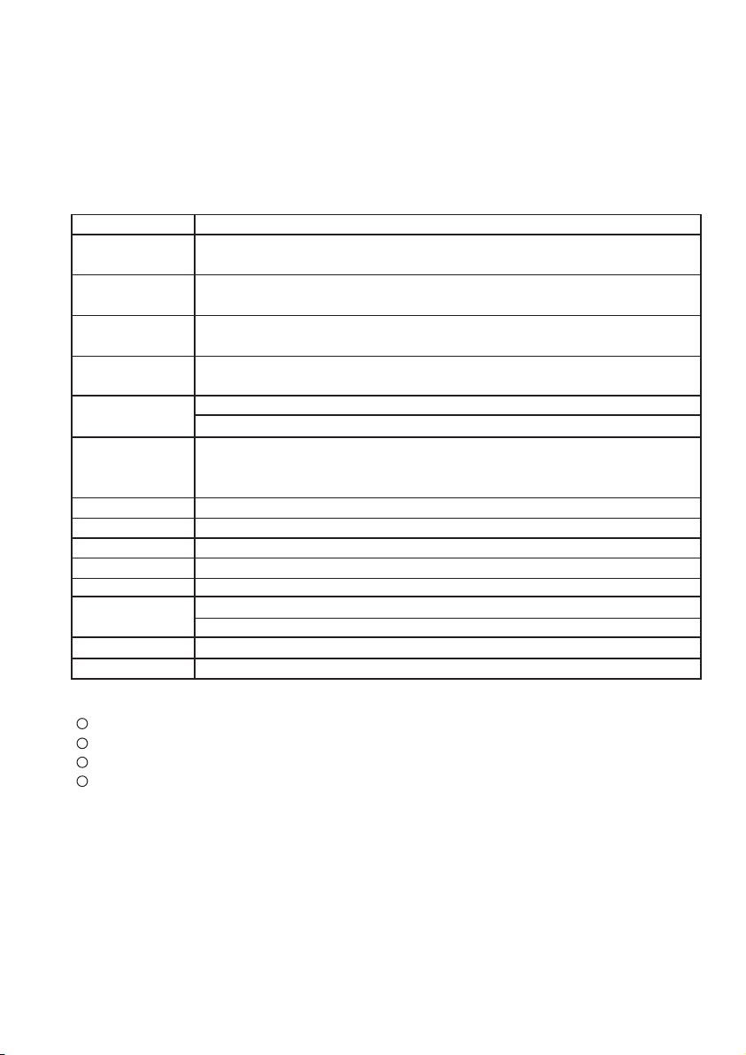
Item Single-phase
Model & Spec.
SVC series
Input
Voltage range
Nominal Output
Voltage
High-Voltage
protection value
Low-Voltage
protection value
Accuracy of
voltage
stabilization
Frequency
Waveform distortion
Load power factor
Efficiency
Adjustable time
Delay time
Electrical strength
Insulation resistance
S1000VA, S2000VA, S3000VA, S5000VA, S8000VA, S10000VA, S12000VA, S15000VA
290±5V
120V±10V
In general, Low voltage protection is provided, however, it can be set under requirement
≤ ±4%V
50-60Hz
No additional waveform distortion
0.8
≤ 90%
<1s (when input voltage has a change of 10%)
Long-time delay: 5±2min; short-time delay: 5±2s
In general, long-time delay function is not provided, however, it can be set under requirement
No flashover or breakdown when it withstands 1.500V/min
≤ 2M Ώ
3. Synchronously output 230VAC.
SVC-3000VA (single - phase) and below products can output 230V.
4. Directly provide commercial power:
SVC - 2000VA (single - phase) and above products include commercial power function;
5. Overload or short - circuit protection: single - phase 1000VA and below products offer fuse to protect against
overload or short circuit ; and other specifications products use circuit breaker.
6. Technical parameters
160-250VAC
230VAC
7. Applicable working conditions
Environment temperature: -5°C~+40°C
Relative humidity : less than 95% (25°C)
Air pressure: 86-106kPa;
Working environment : no chemical deposition, scale, harmful corrosive medium as well as flammable or
explosive gas. Besides, the altitude is not higher than 1,000m.
1
2
3
4
4
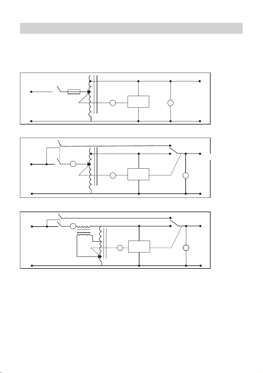
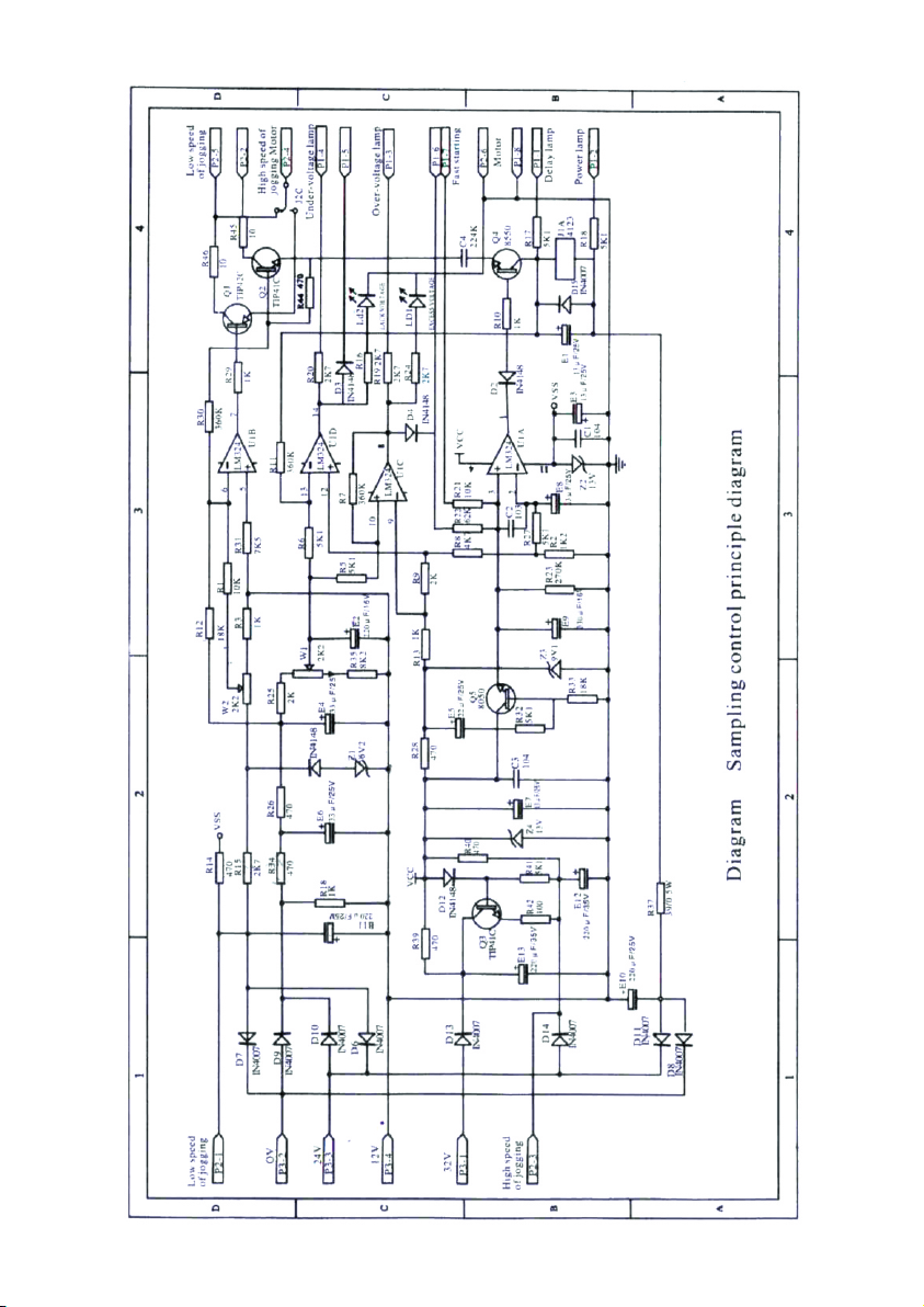
Working principle
1. Circuit diagram (see diagram 2~diagram 4)
2. Sampling control principle (see diagram 5)
(Note: following diagrams are only for reference, if they are changed partially for improving product, we won't
notice separately).
L
N
K
M
L
N
V
Sampling
control circuit Output
Diagram 2: Circuit diagram of SVC series single-phase 500VA~1.5kVA products
Sampling
control circuit
K
L
NN
M
A
V
L
J
Diagram 3: Circuit diagram of SVC series single-phase 2kVA~3kVA products
Diagram 4: Circuit diagram of SVC series single-phase 5kVA & above products
Sampling
control circuit
M
NN
V
L
KAL
J
5
5
5
6
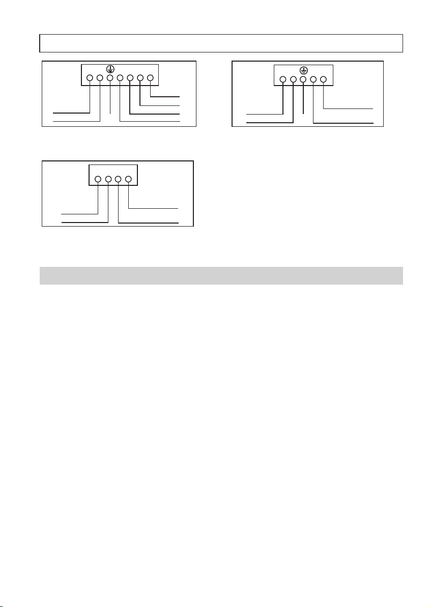
Wiring Connection
Operation instruction
1. before operating, please make sure the voltage of power network is within the range of input voltage permitted
by this equipment, then connect the wires according to the symbol on front and back panel carefully and do not
make mistake, make sure firm grounding. (Input wire of voltage regulator of single-phase 1.kVA and below is
power line, and socket is for output; please refer to diagram 6.
2. Turn on the power switch of the voltage regulator, the output voltmeter of single-phase voltage regulator shall
indicate to 230V check if there is phase failure; only when it is normal voltage regulating that
you can turn on the power switch of consumer.
3. When single - phase voltage regulator outputs 230V and 230V at the same time, the sum of load current can't
exceed the rated value.
4. When it is inductive load (such as air-conditioner and refrigerator), as the starting current of inductive load is
very heavy, please choose voltage regulator whose output capacity is 3-5 times of load power. for other
capacitive and impactive loads, please leave enough allowance for output capacity of voltage regulator.
5. When the mains voltage is rather normal, please use the commercial power, at this time, the voltage regulator
does not have power loss. Open the voltage regulation circuit breaker, and close commercial power circuit breaker.
6. When mains failure happens (include loss of phase) or the input voltage is too high, please turn off the voltage
regulator and the power switch of consumer in time.
Diagram 7: Wiring diagram of SVC series single
-phase 2kVA TO 10kVA.
NN
LL
NOutput 230V
L
Input 160-250V Earth
terminal
Diagram 6: Wiring diagram of SVC series single
-phase 1kVA products
N
L
N
L
Output 230V
Output 230V
L
Input 160-250V
NEarth
terminal
N NNL L L
Diagram 8: Wiring diagram of SVC series single
-phase 12kVA / 15kVA.
NN
LL
NOutput 230V
L
Input 160-250V

7
Attentions
1, Please place the voltage regulator in a draughty environment where is no corrosive gas, explosive gas, conductive
dust or steam, and the children can't touch it, besides, it mustn't subject to the sunshine or rain.
2. The earth terminal must be firm and reliable to ensure safety.
3. The voltage regulator will produce little heat when it works normally, it is not allowed to cover with any things,
otherwise, it would be damaged for not sufficient heat emission.
4. The fluctuation of external voltage that leads the equipment regulates the voltage automatically, it is normal that
there is the friction sound trom gear.
5. Choose input and output leads with suitable sectional area according to the power of voltage regulator, try to
reduce power consumption in the circuit in general, 5A/mm' for copperwire, and reduce half for aluminum wire.
6. The earth wire and neutral wire shall not be connected inversely and the earth wire can't take the place of neutral
wire, otherwise, it wouid cause the equipment body produces electricity or it cant work normally
7. When the voltage regulator is energized, it is forbidden to open the case for adjusting randomly, in order to prevent
the electric shock.
8. In case that the frequency of generation power grid is unstable, but the electricity is needed urgently, user can use
the function of directly providing commercial power, to protect the equipment against damage for unstable
frequency.
9. When the equipment has been used for a long time, a professional clectric worker ahall be invited to clear away
the dust in the machine regularly to keep the clean between carbon brush and coil grinding surface and adjust the
contact pressure between them to get a fine contact against flashover, if thecarbon brush is worn seriously, please
change it in time, to prevent the equipment being damaged.
10. If the equipment works abnormally,user shall cut off the power immediately and send it to the designated place
for maintenance
11. 1f the safety parts for maintenance or change are not provided by us, we won t be responsible for any possible
safety quality problems.
Rev01/SVCSeries/Jan2024
SVC - S15000
This manual suits for next models
8
Table of contents


